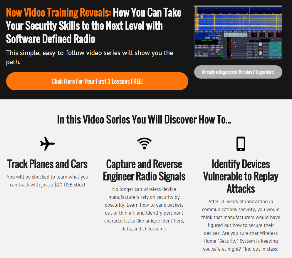
We’ve recently found what looks to be a new online video based course that uses the RTL-SDR to teach basic software defined radio topics. The course is not free, it is priced at $29.99, but the first three videos are free. Judging from the first three videos the content appears to be quite basic, but is presented in a very clear way that may be useful for beginners. Currently the lessons include:
Course Overview
Welcome to the exciting world of Software Defined Radio. In this video, we’ll discuss what SDR is, and why it’s such a hot button topic right now.
Setting up the environment
In this module, we’ll setup our environment for development. If you’re already very comfortable with Ubuntu, you might want to just follow the guide below.
Browsing the spectrum
In this module, we’ll cut our teeth on GRQX, and learn a little about the radio spectrum.
Signals Intelligence
In this module, we’ll learn how to find transmissions in the frequency domain, and capture them to disk for offline analysis.
Modulations
In this module, we’ll learn how to identify two types of basic digital transmissions, and talk a little about the history of radio.
Demodulation – Part 1
In this module, we’ll practice capturing signals in the wild, identifying the modulation, and demodulating the signal with GNU Radio.
Demodulation – Part 2
In this module, we’ll learn about clock recovery. And we’ll pull out packets from the garage door remote.
It also appears that they plan to have some live classes in the future.
We note that there are also alternative SDR training courses available such as Micheal Ossmanns lessons at greatscottgadgets.com/sdr.
As the RTL-SDR’s maximum usable bandwidth is about 2.8 MHz, programs like rtl_power were written to scan over wider bandwidths by quickly hopping between different swaths of the frequency spectrum and then stitching the data together.
Now a new improved version of rtl_power called rtl_power_fftw has recently been developed and released. This version is designed for radio astronomy use, but also overcomes several issues general users may encounter with rtl_power. One of the authors, Klemen wrote in to us with this information:
I would like to tell you about a program we have been developing at Astronomical Society Vega – Ljubljana, namely one for measuring power spectrum with rtl dongles.
It addresses several shortcomings of the rtl_power program shipped with librtlsdr. The most notable is that it uses a much faster FFT algorithm (from the fftw3 library) and separate threads for acquiring data and FFT processing. This means that even the lowly raspberry pi is capable of processing spectra of sizes up to ~1024 bins in real-time (no slower than data acquisition). This enables the user to sample spectrum continuously and more efficiently.
The other benefit is the output format: data is presented in a gnuplot-friendly way, so plotting is simple, and no data is mangled to make an illusion that spectral hopping is not needed: FFT of each frequency hop is output separately, and user can make and informed decision on how to process data – the program stays out of this, to preserve the accuracy of the gathered data.
The program was developed for use in radio astronomy where all these things matter. Code is available on Github:
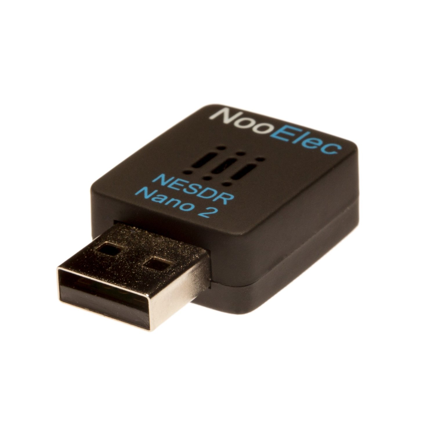
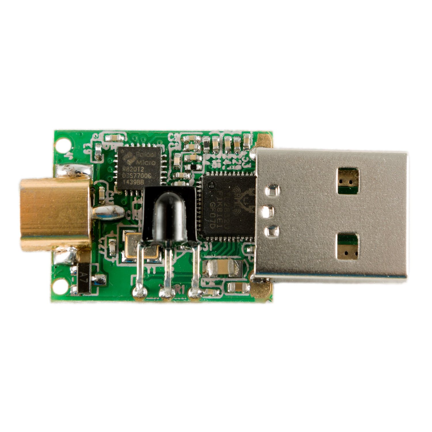
The Nooelec store have recently come out with a new small RTL-SDR model called the Nano 2, which appears to an improved version of the old tiny square dongles. These new ones are sized at 24mm x 21mm x 8mm and come in a new plastic case with vent holes to prevent overheating. They also come with the newer R820T2 tuner chip. This appears to be a good improvement over the older models which were reported to have overheating and thermal frequency drift issues.
These small dongles look to be great for embedded or mobile phone applications that have space restrictions.
The new dongle is currently selling for $24.95 USD + $1.99 shipping.
The Nano 2 with vent holes in the case.The Nano 2 circuit.
Docker is a Linux based platform which allows you to build and deploy complex applications into a self contained “container” package that contains all the needed applications and dependencies. The container is completely preconfigured to just work as soon as you install the application without the need for any extra configuration.
The team behind the Airspy software defined radio (as well has the popular SDR# software package) have just released the SpyVerter upconverter for sale. Upconverters shift HF frequencies (0 – 30 MHz) “up” by a fixed amount, giving receivers that can’t tune that low like the RTL-SDR and the Airspy the ability to receive HF signals.
The SpyVerter extends reception all the way down to DC and has a 60 MHz low pass filter. Its main selling point is its H-Mode architecture which provides excellent IIP3 performance. This basically means that strong HF signals are unlikely to cause overloading in the up-conversion stage. The good IIP3 performance should improve HF reception when compared to other upconverters even with lower end SDR’s like the RTL-SDR. The reason is that when hit by strong HF signals many other upconverters will overload in the upconversion mixing stage, before even reaching the SDR, thus requiring the need for attenuators or antennas with less gain.
Another selling point is its good performance down to DC, making it ideal for VLF reception.
SpyVerter is designed for optimal performance with the Airspy and can be powered directly by the Airspy’s bias tee. However, RTL-SDR users can also use the SpyVerter by powering it through the micro USB connector, or by using it with one of our RTL-SDR Blog units with the activatable bias tee.
The SpyVerter sells for $59 USD and comes in a metal enclosure with three bonus SMA adapters. There is a $9 USD discount for Airspy owners.
At these prices combined with its claimed performance and metal enclosure we now generally recommend the SpyVerter over any other upconverter. The designers of the SpyVerter have sent us a sample unit and we will review it after testing it out over the next few weeks, but our initial tests already show good performance.
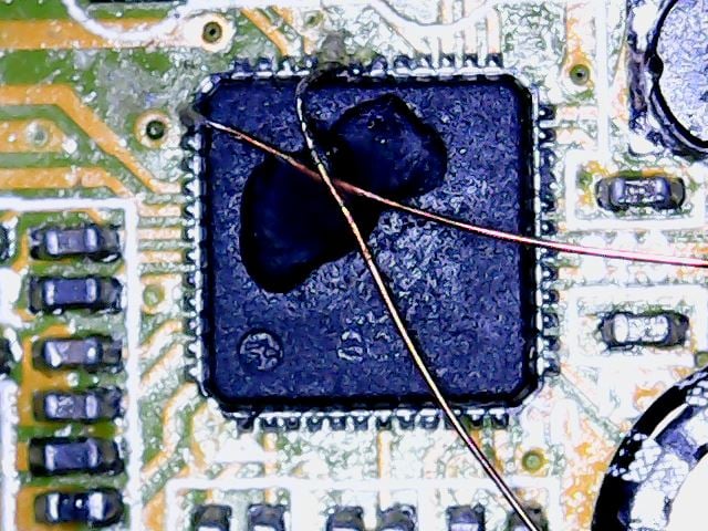
The RTL-SDR uses the RTL2832U chip as its ADC and USB interface processing chip. It also has 8 GPIO (General Purpose IO) ports available which are by default unused by the original DVB-T dongle application. However, which the right modifications to the SDR drivers, these GPIO ports can be activated and potentially used for applications such as antenna, filter, pre-amplifier and attenuator switching.
Over on his web site S57UUU has been experimenting with these GPIO ports and has put up a short tutorial/set of notes on how to connect to the ports and how to modify the RTL-SDR drivers to set the state of each pin. You will need basic programming and compilation knowledge to understand how to activate these pins in the drivers, as well as good surface mount soldering skills to be able to connect wires to the pins.
Connecting to the GPIO ports requires good SMT soldering skills.
The performance of WiFi networks can depend heavily on how crowded the WiFi channels are in your area. For example when your neighbours start streaming a movie over their own separate WiFi network, it can cause your own WiFi connection to slow down. This happens because generally separate WiFi networks do not collaborate with one another, and when two packets are sent on the same channel at the same time, they collide causing no packets to get through.
There are several methods that attempt to stop collisions, but none are very efficient because WiFi nodes are not synchronized to one another. If each WiFi node could be synchronized to a common reference time, then avoiding collisions is made easier.
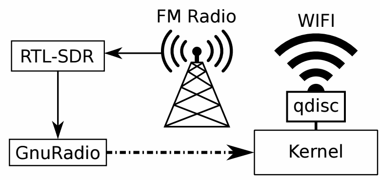
Marcel Flores, Uri Klarman, and Aleksandar Kuzmanovic from Northwestern University have been working on this idea and have come up with a system they have termed Wi-FM which is based on FM RDS signals. Many FM radio stations transmit a digital Radio Data System (RDS) subcarrier on their broadcast frequency. This RDS signal is often used to simply display information on the radio such as the station name and current song playing.
Since each nearby WiFi node should be able to receive the same RDS signal at the exact same time, it can be used as a common synchronization signal. Then once synchronized each WiFi node can listen to the other nodes and work out what their transmit scheduling is like and then optimize their own transmit schedule.
In their prototyping they used an RTL-SDR dongle connected to a PC running GNU Radio. The GNU Radio program decodes the RDS signal and the resulting information is sent to the Linux kernel which handles the WiFi transmit schedule processing.
The prototype watch does this by using the RTL-SDR to detect the electromagnetic (EM) noise emitted by particular objects and compare it against a stored database. They call this technology EM-Sense. In the paper the authors summarize:
Most everyday electrical and electromechanical objects emit small amounts of electromagnetic (EM) noise during regular operation. When a user makes physical contact with such an object, this EM signal propagates through the user, owing to the conductivity of the human body. By modifying a small, low-cost, software-defined radio, we can detect and classify these signals in real-time, enabling robust on-touch object detection. Unlike prior work, our approach requires no instrumentation of objects or the environment; our sensor is self-contained and can be worn unobtrusively on the body. We call our technique EM-Sense and built a proof-of concept smartwatch implementation. Our studies show that discrimination between dozens of objects is feasible, independent of wearer, time and local environment.
The frequencies required for EM detection are around 0 - 1 MHz which falls outside the range of the RTL-SDR's lowest frequency of 24 MHz. To get around this, they ran the RTL-SDR in direct sampling mode. The RTL-SDR is connected to the watch, but a Nexus 5 smartphone is used to handle the USB processing which streams the signal data over WiFi to a laptop that handles the signal processing and live classification. In the future they hope to use a more advanced SDR solution, but the RTL-SDR has given them the proof of concept needed at a very low cost.
An example use scenario of the watch that Disney suggests is as follows:
Home – At home, Julia wakes up and gets ready for another productive day at work. Her EM-Sense-capable smartwatch informs and augments her activities throughout the day. For instance, when Julia grabs her electric toothbrush, EMSense automatically starts a timer. When she steps on a scale, a scrollable history of her weight is displayed on her smartwatch automatically. Down in the kitchen, EM-Sense detects patterns of appliance touches, such as the refrigerator and the stove. From this and the time of day, EM-Sense infers that Julia is cooking breakfast and fetches the morning news, which can be played from her smartwatch.
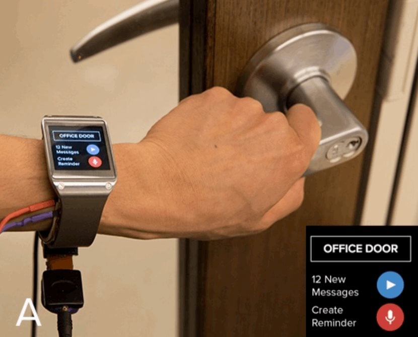
Fixed Structures – When Julia arrives at the office, EMSense detects when she grasps the handle of her office door. She is then notified about imminent calendar events and waiting messages: "You have 12 messages and a meeting in 8 minutes". Julia then leaves a reminder – tagged to the door handle – to be played at the end of the day: “Don’t forget to pick up milk on the way home.”
Workshop – In the workshop, EM-Sense assists Julia in her fabrication project. First, Julia checks the remaining time of a 3D print by touching anywhere on the print bed – “five minutes left” – perfect timing to finish a complementary wood base. Next, Julia uses a Dremel to cut a piece of wood. EM Sense detects the tool and displays its rotatory speed on the smartwatch screen. If it knows the task, it can even recommend the ideal speed. Similarly, as Julia uses other tools in the workshop, a tutorial displayed on the smartwatch automatically advances. Finally, the 3D print is done and the finished pieces are fitted together.
Office – Back at her desk, Julia continues work on her laptop. By simply touching the trackpad, EM-Sense automatically authenticates Julia without needing a password. Later in the day, Julia meets with a colleague to work on a collaborative task. They use a large multitouch screen to brainstorm ideas. Their EM-Sense-capable smartwatches make it possible to know when each user makes contact with the screen. This information is then transmitted to the large touchscreen, allowing it to differentiate their touch inputs. With this, both Julia and her colleague can use distinct tools (e.g., pens with different colors); their smartwatches provide personal color selection, tools, and settings.
Transportation – At the end of the day, Julia closes her office door and the reminder she left earlier is played back: “Don’t forget to pick up milk on the way home.” In the parking lot, Julia starts her motorcycle. EM-Sense detects her mode of transportation automatically (e.g., bus, car, bicycle) and provides her with a route overview: “You are 10 minutes from home, with light traffic”.
The EM-Sense watch detecting a door. The RTL-SDR dongle is the small square box under the watch.
EM-Sense: Touch Recognition of Uninstrumented Electrical and Electromechanical Objects