Tagged: rtl-sdr

New R820T Driver with LNA/Mixer/VGA Gain Settings

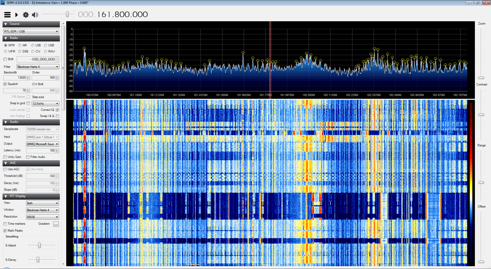
A few weeks ago we posted about an unreleased modified RTL-SDR driver for SDR# by mm6dos which had controls for the three separate gain stages available in the R820T and some extra controls for controlling software decimation and the IF filter. While that particular driver has not yet been released, a modified driver from randaller, another driver coder has been released. His modified driver enables the LNA/Mixer/VGA gain controls, but does not enable any IF filter or decimation settings.

In the standard R820T driver one of the gain stages is locked to a pre-specified value and the the gain slider is a function of the other two gain values. Having full manual control over all three gain stages may help with optimizing signal SNR levels and reducing noise.

To install the driver simply extract the contents of the zip file from the sourceforge download into the sdrsharp folder. Then open the SDRSharp.exe.Config file in a text editor and add the line  in the section. Then in SDR# you can choose “RTL-SDR / GUSB” from the source menu to use the new driver.

Modded Driver with Extra Gain Controls

Recording Video of Passing Aircraft with A Raspberry Pi and RTL-SDR

Electronics experimenter Simon Aubury has recently made a write up on his blog about a project he has been working on. His project is the use of a Raspberry Pi with servo mounted video camera and RTL-SDR to automatically track and record video of passing aircraft.

Simon’s project works by using the RTL-SDR connected to the Raspberry Pi as an ADS-B receiver. From the ADS-B signals the current coordinates of nearby aircraft can be determined. Then by using some coordinate math, the Raspberry Pi can be told to point its camera in the direction of the aircraft. As well as videoing the passing aircraft, the Raspberry Pi also overlays text on to the video showing information such as flight number, source and destination airports, aircraft type, elevation and distance and date of observation.

In addition to all that, his software also automatically uploads the recorded videos onto his website. Here you can see the latest and closest video captures his system has performed.

[Discovered on Hackaday]

Raspberry Pi RTL-SDR Plane Tracker Video Capture

Comparisons between the R820T and R820T2 RTL-SDR Tuners

Over on the hamradioscience blog the author has uploaded a post showing a comparison between the R820T and the R820T2 tuners.

Recently Nooelec began selling RTL-SDR dongles with the R820T2 tuner chip in them. The R820T2 tuner has been anecdotally reported as having slightly better sensitivity (~2-6 dB better). It also works much better with Oliver Jowetts experimental RTL-SDR driver which enables HF reception without any hardware modifications.

In the post the author compares the two tuners by simultaneously running both with SDR# and the same antenna type and comparing the results. From his results the author writes that although not night and day, there is a noticeable difference in sensitivity between the two tuners. He also writes that for ADS-B the R820T2 performed much better, reporting significantly more packets and further distances compared to the R820T.

Comparison between the R820T2 and R820T on a NOAA weather station. (R820T2 Top, R820T Bottom)

RTL-SDR Tutorial: Listening to TETRA Radio Channels

NOTE: There is now a plugin available for SDR# that will decode TETRA fairly easily. It is still in beta and misses a few features found in telive. Check it out in this post.

TETRA is a trunked radio communications system that stands for "Terrestrial Trunked Radio". It is used heavily in many parts of the world, except for the USA. Recently, a software program called Tetra Live Monitor (telive) was released on GitHub. This software can be used along with the (patched) Osmo-TETRA software to monitor and listen to unencrypted TETRA communications.

Below we show a tutorial on how to listen to TETRA communications using a RTL-SDR RTL2832U software defined radio. This tutorial is based heavily on the telive_doc.pdf file that is written by the author of telive and included in the telive git download. Please refer to that pdf file for further details on how the software works. We have modified their tutorial slightly to make it a little easier to understand. As this code is still under heavy development if you have trouble please check their PDF file for modifications to the procedures.

Again, we reiterate: This tutorial is not a substitute for a thorough reading of the documentation. If you have trouble setting this software up, please refer to the telive documentation first, before asking any questions. It contains a comprehensive FAQ section which solves most of the common problems. The documentation can be found directly at https://github.com/sq5bpf/telive/raw/master/telive_doc.pdf. There is also a discussion at http://forums.radioreference.com/digital-voice-decoding-software/302347-tetra-decoding.html.

Decoding and Listening to TETRA Tutorial

Most of this tutorial is performed in Linux and we assume that you have some decent Linux experience. We also assume you have some experience with the RTL-SDR dongle and have a decent antenna capable of picking up TETRA signals in your area. If you don't have a RTL-SDR dongle yet see our Buy RTL-SDR dongles page.

Note: As of October 2016 there is now a Windows port of the Telive decoding software available. This may be an option for you if you prefer to run in Windows. More information here.

First, we will need to find some TETRA signals. The easiest way to do this is to open SDR# or another program like GQRX and look for them. TETRA signals are continuously broadcasting with a bandwidth of around 25 kHz. In most European countries they can be found at 390 - 470 MHz. In some countries they may be found around 850 MHz or 915 - 933 MHz. There may be several TETRA signals grouped in close proximity to one another. See the example images below.

 
A Zoomed in TETRA Signal
 
TETRA Signals Zoomed Out
A Grouping of TETRA Signals Zoomed Out

An example audio clip of a TETRA signal recorded in NFM mode is shown below.

Once you have found some TETRA signals, record their frequencies. Now close SDR#, or whatever software you were using and boot into Linux. In this tutorial we use a 32-bit Ubuntu 14.04 virtual machine running on VMWare Player as our Linux system. Some of the commands may vary if you are using a different system.

Continue reading

RTL-SDR Based Passive Aircraft Radar

Over on YouTube we’ve discovered a video from earlier in the year showing the RTL-SDR being used as a passive aircraft radar. This is different to ADS-B which is a type of active radar. A passive radar works by using a very strong radio signal from a readily available source such as a TV or FM radio transmitter and detecting the reflections from aircraft.

A RTL-SDR based passive radar system can be built by connecting two RTL-SDR dongles to a single clock source and by using two directional antennas.

We’ve also posted about RTL-SDR based passive radar being used to track aircraft here and here in the past. Another post about coherent multichannel RTL-SDR receivers can be found here.

Updates to Shielding the RTL-SDR with an Aluminium Case

A few weeks ago we posted about will1384 who had bought an aluminium case from Ebay and was using it to shield his RTL-SDR. After running multiple tests, will1384 discovered that the aluminium case was actually not helping with shielding performance at all. Oddly his results showed that the aluminium case was actually increasing the amount of noise received. Will has been updating his imgur album with noise analysis results from rtl_power scans over the entire spectrum.

In his latest tests he tried a metal outlet box as the case and saw improved results over the aluminium case. His conclusions seem to indicate that the aluminium box is not a good EMI shield. We’re not sure why he found these results, but one theory might be that because the aluminium case is anodized, it has a non-conductive surface, which might cause poor grounding.

RTL-SDR in a Metal Outlet Box

RTL-SDR As a Spectrum Analyzer

Hackaday has brought to attention a blog post by Kerry Wong which shows how the RTL-SDR can be used as a simple and inexpensive spectrum analyzer. In the past we’ve already posted numerous examples of the RTL-SDR being used as a spectrum analyzer but Kerry’s post discusses some of the do’s and don’ts that you need to think about when using a SDR as a spectrum analyzer and also provides some measurements.

During his tests he discovered that popular software like RTLSDR Scanner and SDR# either distort the spectrum or don’t display the signal amplitude correctly. Only GQRX and osmocom_fft seemed to give an accurate depiction of the spectrum.

Kerry also discusses how to calibrate the spectrum display to show proper power levels, how to set the gain for spectrum analysis and discusses some thoughts on LO leakage.

Using an RTL-SDR as a spectrum analyzer with osmocom_fft

Improving HF Reception By Disconnecting the Switching Power Supply on the RTL-SDR

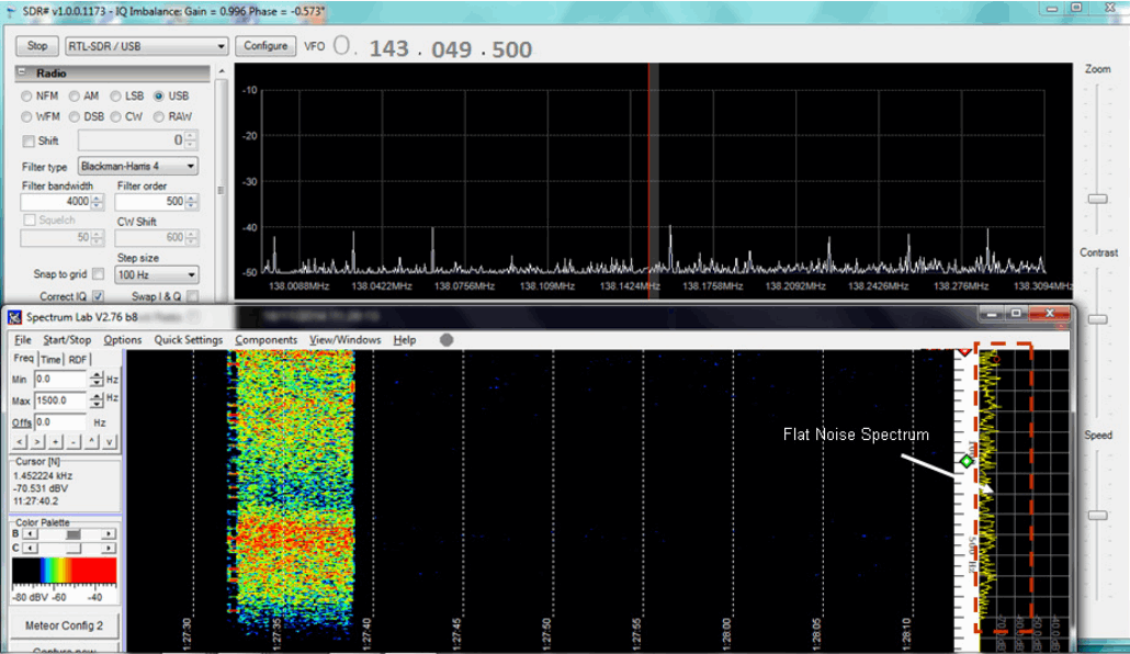
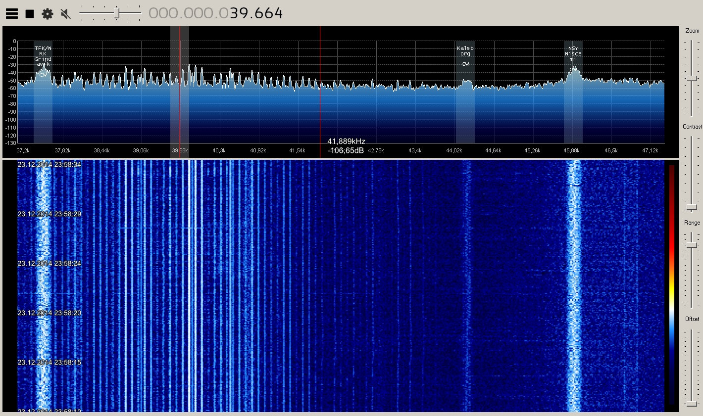
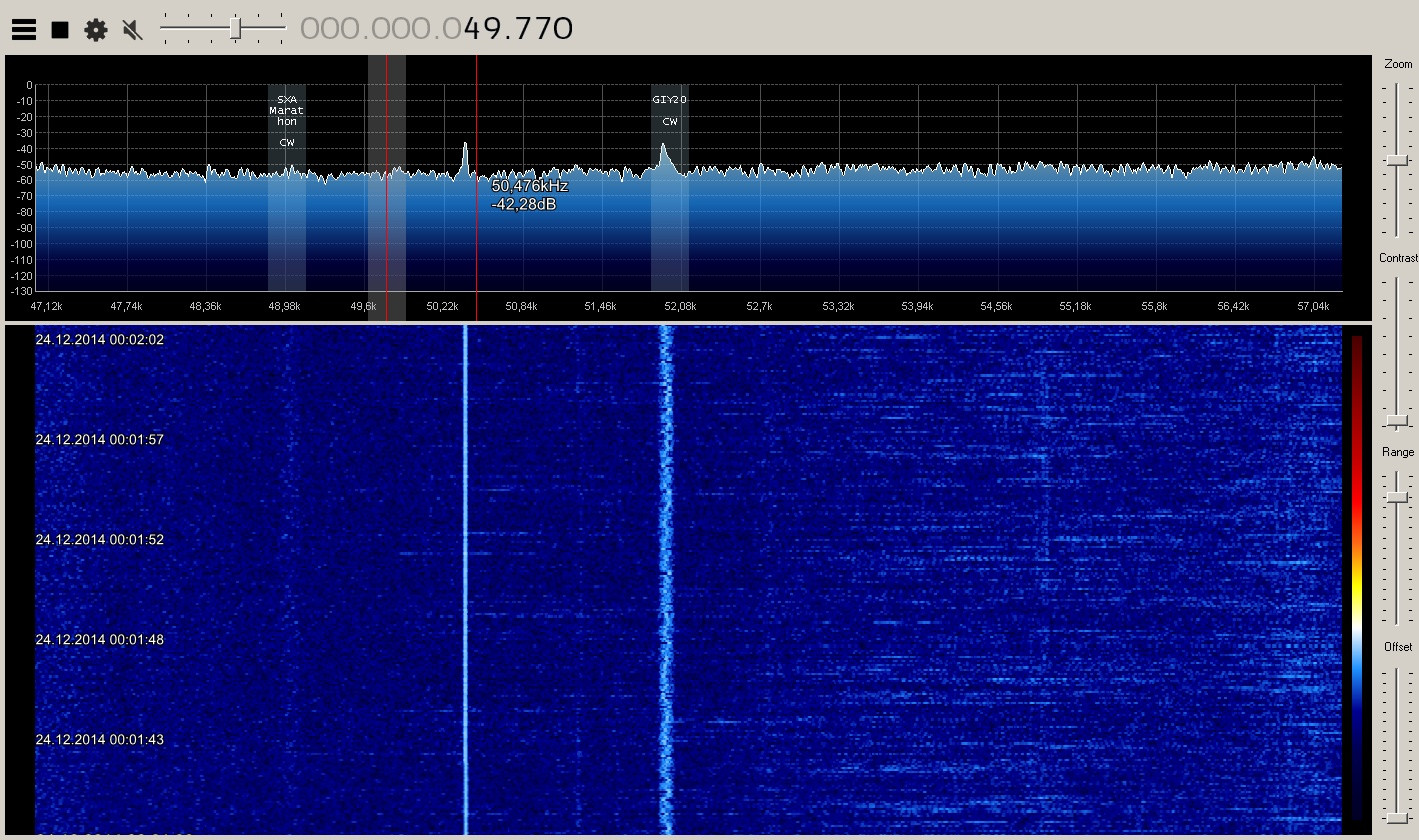
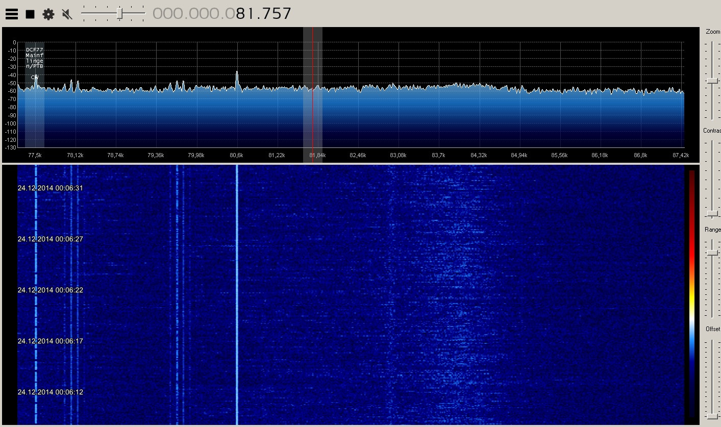
By using an upconverter, direct sampling mod, or experimental software driver the RTL-SDR can be used for HF reception. However, a problem with HF reception and the RTL2832U chip is that it uses a switching power supply in its design. This switching power supply causes significant amounts of noise spurs to appear in the HF spectrum.

Japanese RTL-SDR experimented ttrftech has recently posted about a modification to the RTL-SDR which he performed (note in Japanese, use Google translate to read). The purpose of the switching power supply in the RTL2832U is to step 3.3v down to 1.2v. In his modification, ttrftech disconnected the switching power supply and instead stepped 3.3v down to 1.2v by using three diodes. This works as each diode has a voltage drop across it of 0.7v.

His results show that there is a significant reduction in noise spurs at HF frequencies.

Switching power supply replaced by three diodes.
Unmodded reception at 7 MHz
Modded reception at 7 MHz