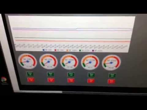
To gather the power usage data he used an RTL-SDR connected to a PC running rtlamr, which is software that can read data from ERT compatible power meters that transmit in the 900 MHz ISM band. He also uses some custom code he wrote that automatically plots the data over time and allows him to integrate it with his home automation system. In addition to his post he also uploaded a video shown below that shows his system in action.
Monitoring house power using a $20 RF RTLSDR USB stick
Over on YouTube user Jane feverlay has uploaded a video showing a new AIS decoder called AISRec for Windows that he has developed.
AIS is an acronym for Automatic Identification System and is a system used by ships to broadcast position and vessel information. By monitoring AIS transmissions with the RTL-SDR we can build a boat radar system. We have a tutorial on this here.
The new software is not free, but he offers a trial version that limits the run time to 20 minutes and 5000 max messages. The paid version removes these limits and also decodes both AIS channels simultaneously. The program monitors data from the RTL-SDR and sends decoded data out via UDP. Software such as OpenCPN can then be used to display the AIS data on a map.
We tested the trial version on our machine and found that it worked well at decoding AIS messages. To download the trial go to http://pan.baidu.com/s/1pJiEzEV and enter the code kn44. The download site is in Chinese, but it is obvious where to enter the code. We found the software to be virus free, but remember to always scan unknown software like this yourself. The full price of the software is unknown, but purchasing instructions are given in the trial download readme. The author also writes that his software now supports the Airspy, but not in the trial version.
Note that we discovered that the software doesn’t use a PPM correction setting as expected. Instead it uses a frequency shift setting. To set the shift in the AISRec.ini file, we had to calculate freqshift = 162.025 MHz – frequency of the second AIS channel as shown in SDR# with no PPM correction set.
Pothos is a dataflow processing platform that can be used for signal processing through a graphical GUI that works in a similar way to GNU Radio. Over on YouTube the developers have released a tutorial video that shows how to use Pothos to interact with an RTL-SDR dongle. In the video they create a design which shows an RF spectrum and waterfall display.
Hey all, sorry about dropping off the radar there. There were several large unexpected events in recent months, but nothing bad. I’ve still been hacking on the project. An anonymous donor gave me a Lyons DSP textbook, which I’ve been working through for more solid foundations. But studying doesn’t generate any new code for you to play with, so hasn’t been counted towards the project.
I’ve also been working on a very ambitious ADS-B related side project. It is something no one has ever done before with the RTL-SDR, but mathematically it is feasible and progress is steady. Not anywhere near for a release (and might yet be impossible in practice), and thus also hasn’t been counted towards the project.
So what has been completed since the last report?
* Automatic audio gain. Crucial for AM/SSB listening.
* Audio padding (constant rate audio). If you are streaming rtl_fm, this will prevent stutters when the tuner is busy hopping.
* Heatmap fixes. The font is downloaded automatically and image slicing is completed. Run rtl_power 24×7 but render a heatmap of only the last hour, for example.
* Rtl_power fixes. Including one tricky corner case that caused crashes.
Also a big thank you to Kacper Michajłow who fixed and fleshed out a couple of Windows issues that were giving me trouble.
25 days remain. As always, if you have comments or suggestions you can reach me by email or in ##rtlsdr.
The latest feature requests and links to the GitHub repositories and Windows builds can be found at http://igg.kmkeen.com/.
A few weeks ago we posted about an unreleased modified RTL-SDR driver for SDR# by mm6dos which had controls for the three separate gain stages available in the R820T and some extra controls for controlling software decimation and the IF filter. While that particular driver has not yet been released, a modified driver from randaller, another driver coder has been released. His modified driver enables the LNA/Mixer/VGA gain controls, but does not enable any IF filter or decimation settings.
In the standard R820T driver one of the gain stages is locked to a pre-specified value and the the gain slider is a function of the other two gain values. Having full manual control over all three gain stages may help with optimizing signal SNR levels and reducing noise.
To install the driver simply extract the contents of the zip file from the sourceforge download into the sdrsharp folder. Then open the SDRSharp.exe.Config file in a text editor and add the line in the section. Then in SDR# you can choose “RTL-SDR / GUSB” from the source menu to use the new driver.
Simon’s project works by using the RTL-SDR connected to the Raspberry Pi as an ADS-B receiver. From the ADS-B signals the current coordinates of nearby aircraft can be determined. Then by using some coordinate math, the Raspberry Pi can be told to point its camera in the direction of the aircraft. As well as videoing the passing aircraft, the Raspberry Pi also overlays text on to the video showing information such as flight number, source and destination airports, aircraft type, elevation and distance and date of observation.
In addition to all that, his software also automatically uploads the recorded videos onto his website. Here you can see the latest and closest video captures his system has performed.
In the post the author compares the two tuners by simultaneously running both with SDR# and the same antenna type and comparing the results. From his results the author writes that although not night and day, there is a noticeable difference in sensitivity between the two tuners. He also writes that for ADS-B the R820T2 performed much better, reporting significantly more packets and further distances compared to the R820T.
Comparison between the R820T2 and R820T on a NOAA weather station. (R820T2 Top, R820T Bottom)
NOTE: There is now a plugin available for SDR# that will decode TETRA fairly easily. It is still in beta and misses a few features found in telive. Check it out in this post.
TETRA is a trunked radio communications system that stands for "Terrestrial Trunked Radio". It is used heavily in many parts of the world, except for the USA. Recently, a software program called Tetra Live Monitor (telive) was released on GitHub. This software can be used along with the (patched) Osmo-TETRA software to monitor and listen to unencrypted TETRA communications.
Below we show a tutorial on how to listen to TETRA communications using a RTL-SDR RTL2832U software defined radio. This tutorial is based heavily on the telive_doc.pdf file that is written by the author of telive and included in the telive git download. Please refer to that pdf file for further details on how the software works. We have modified their tutorial slightly to make it a little easier to understand. As this code is still under heavy development if you have trouble please check their PDF file for modifications to the procedures.
Most of this tutorial is performed in Linux and we assume that you have some decent Linux experience. We also assume you have some experience with the RTL-SDR dongle and have a decent antenna capable of picking up TETRA signals in your area. If you don't have a RTL-SDR dongle yet see our Buy RTL-SDR dongles page.
Note: As of October 2016 there is now a Windows port of the Telive decoding software available. This may be an option for you if you prefer to run in Windows. More information here.
First, we will need to find some TETRA signals. The easiest way to do this is to open SDR# or another program like GQRX and look for them. TETRA signals are continuously broadcasting with a bandwidth of around 25 kHz. In most European countries they can be found at 390 - 470 MHz. In some countries they may be found around 850 MHz or 915 - 933 MHz. There may be several TETRA signals grouped in close proximity to one another. See the example images below.
A Zoomed in TETRA Signal
A Grouping of TETRA Signals Zoomed Out
An example audio clip of a TETRA signal recorded in NFM mode is shown below.
Once you have found some TETRA signals, record their frequencies. Now close SDR#, or whatever software you were using and boot into Linux. In this tutorial we use a 32-bit Ubuntu 14.04 virtual machine running on VMWare Player as our Linux system. Some of the commands may vary if you are using a different system.