Testing the Outernet Dreamcatcher: Linux Based ARM PC with Built in RTL-SDR
Last week we posted about Outernet's new Dreamcatcher unit which is an RTL-SDR + L-band LNA + computing board all on the same PCB. The Dreamcatcher comes with a new active ceramic L-band patch antenna, costs $99 USD (plus shipping) and can be bought directly from their store. Outernet were kind enough to send us a review unit, and we've been testing it for the past few weeks. This post is a review of the unit.
Background
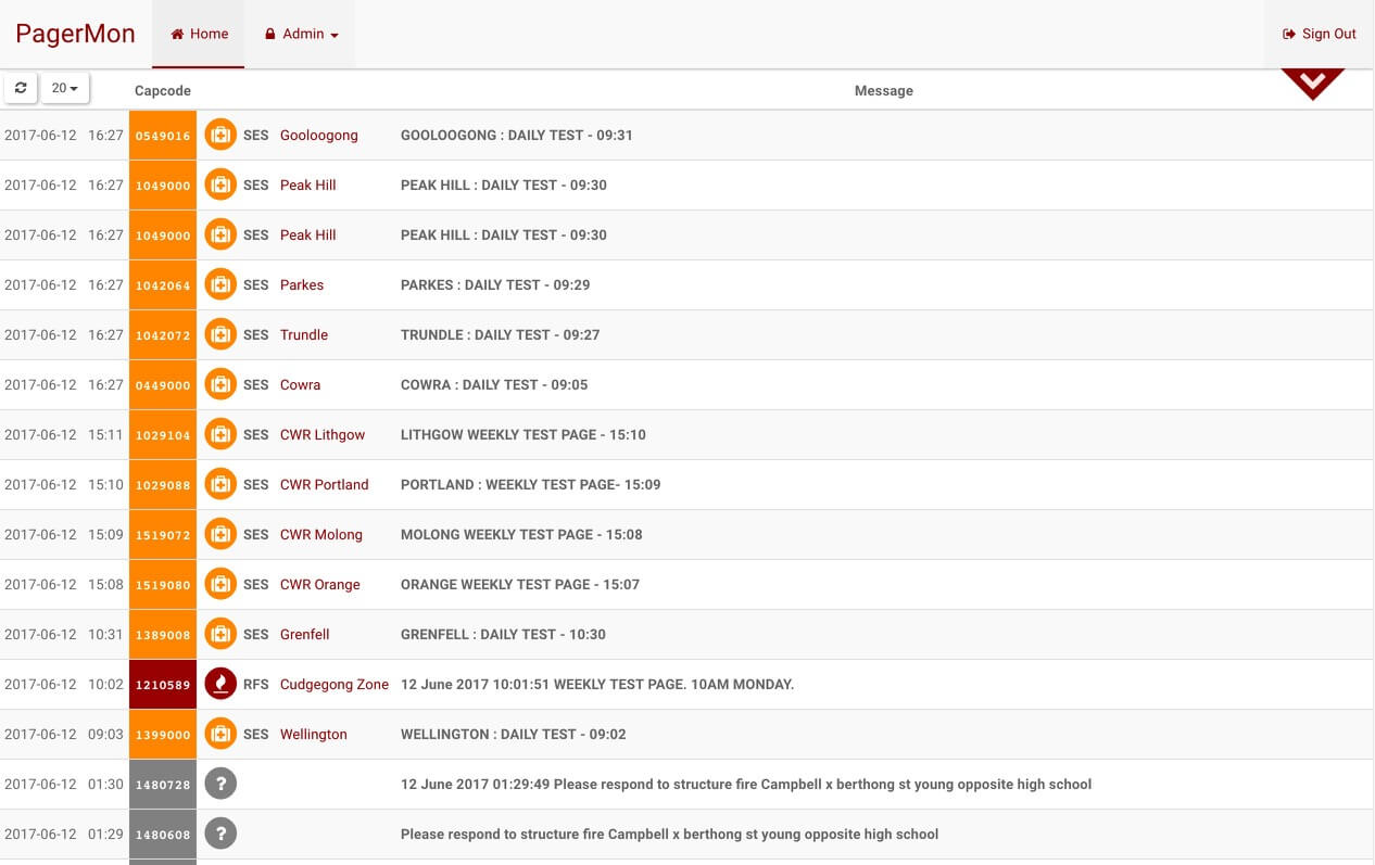
Outernet is a free data service that uses L-band satellites to beam down information like news, weather updates, Wikipedia articles, books and more.
In the past Outernet have used the $9 USD C.H.I.P computing board, an RTL-SDR dongle and an external LNA as the receiving hardware for their data service. However, popularity of the Outernet service has been severely hindered by the huge supply shortages of the C.H.I.P. Over the past year or so it has been almost impossible to get a hold of a C.H.I.P unit if you did not back the Kickstarter or buy one from Outernet's first initial stock. By manufacturing their own PCB including the computing hardware, Outernet must be hoping to be able to control their stock situation, and not rely on third parties who may not be able to deliver.
At the moment the Dreamcatcher can only be run on their new Armbian image. The older Skylark image has been removed from their servers presumably because the Outernet signal is going to change in the near future and the old demodulator on Skylark may no longer work. The Armbian image is basically just standard Armbian and at the moment does not actually run any Outernet software, and cannot decode their signal, but this is being worked on. Eventually they hope to replace Skylark with a standard decoding app that runs on Armbian.
In this post we'll review the Dreamcatcher with Armbian and consider it as a general purpose receiver (not just for Outernet), and we'll also review the new active ceramic patch antenna as well.
Dreamcatcher Overview
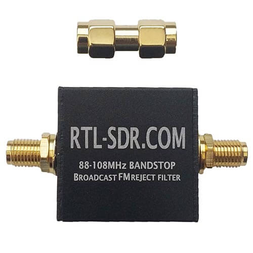
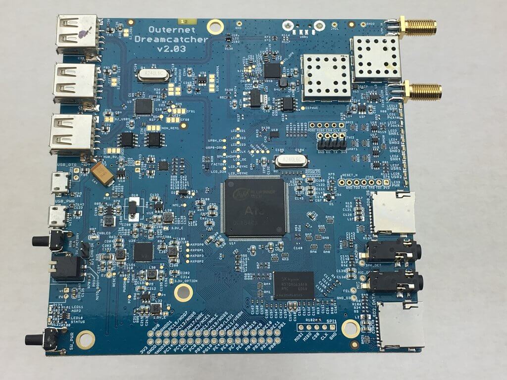
The Dreamcatcher is a single PCB that combines an RTL-SDR, Linux (Armbian) based computing hardware, and an L-band LNA and filter.
On first impressions we noticed that the PCB is relatively large square at about 12 cm by 12 cm. The most prominent chip is the Allwinner A13 SoC. The RTL-SDR circuitry is positioned in the upper right with the RF sections (R820T and LNA) both covered with RF shielding cans. There is no onboard WiFi circuitry, but a small 'EDUP' branded WiFi dongle is included and plugs into one of the USB ports on the PCB.
We measured the Dreamcatcher to be using about 400 mA - 600 mA while idle and 800 mA while utilizing the RTL-SDR and 100% CPU. Heat is not an issue as the Dreamcatcher stays relatively cool during its operation even at 100% CPU with the CPU only getting up to about 45 degrees C.


![[EN subs] ADSB Antenne für 2€ - DIY](https://www.rtl-sdr.com/wp-content/plugins/wp-youtube-lyte/lyteCache.php?origThumbUrl=https%3A%2F%2Fi.ytimg.com%2Fvi%2FU6ae4E75ICY%2F0.jpg)