Category: Antennas

Locating a Radio Transmitter with Direction Finding Techniques and KerberosSDR our 4-Tuner Coherent RTL-SDR

KerberosSDR is our upcoming low cost 4-tuner coherent RTL-SDR. With four antenna inputs it can be used as a standard array of four individual RTL-SDRs, or in coherent applications such as direction finding, passive radar and beam forming. More information can be found on the KerberosSDR main post. Please remember to sign up to our KerberosSDR mailing list on the main post or at the end of this post, as subscribers will receive a discount coupon valid for the first 100 pre-order sales. The list also helps us determine interest levels and how many units to produce.

In this post we'll show an experiment that we performed which was to pinpoint the location of a transmitter using KerberosSDR's coherent direction finding capabilities. RF direction finding is the art of using equipment to determine the location of a transmitting signal. The simplest way is by using a directional antenna like a Yagi to try and determine the bearing based on signal strength. Another method is using a pseudo-doppler or coherent array of antennas to determine a bearing based on phase information.

For the test we tuned the KerberosSDR RTL-SDRs to listen to a signal at 858 MHz and then drove to multiple locations to take direction readings. The antennas were set up as a linear array of four dipole antennas mounted on the windshield of a car. To save space, the dipoles were spaced at approximately a 1/3 the frequency wavelength, but we note that optimal spacing is at half a wavelength. The four dipole antennas were connected to KerberosSDR, with a laptop running the direction finding demo software. 
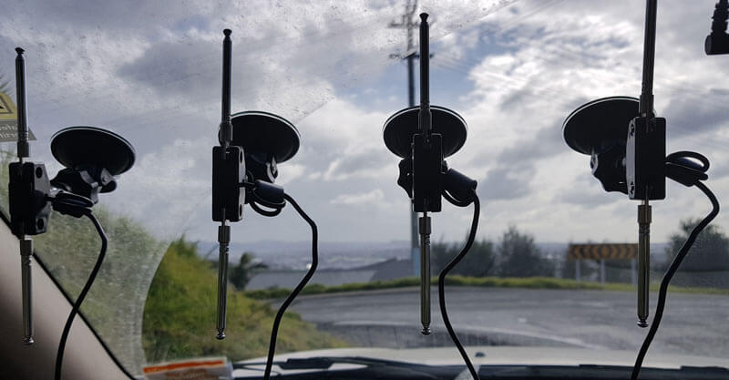
Low cost direction finding array mounted to vehicle windshield.

Our open source demo software (to be released later when KerberosSDR ships) developed by Tamás Peto gives us a graph and compass display that shows the measured bearing towards the transmitter location. The measured bearing is relative to the antenna array, so we simply convert it by taking the difference between the car's bearing (determined approximately via road direction and landmarks in Google Earth) and the measured bearing. This hopefully results in a line crossing near to the transmitter. Multiple readings taken at different locations will end up intersecting, and where the intersection occurs is near to where the transmitter should be. 
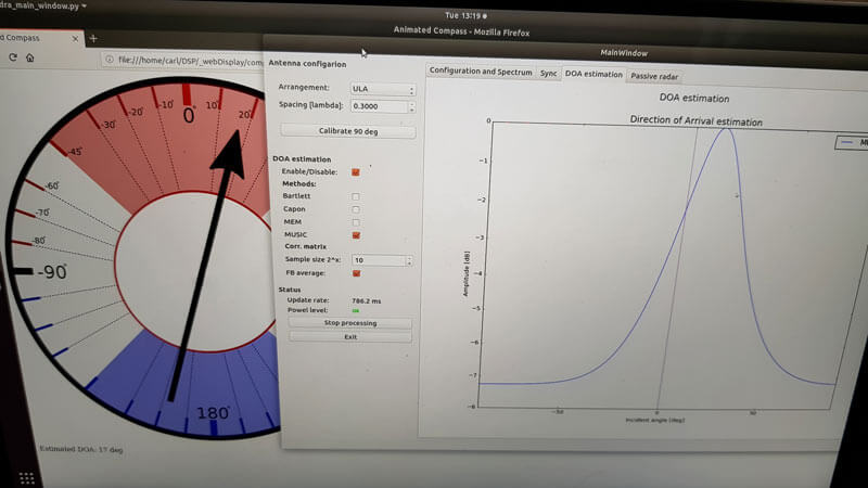
KerberoSDR SDR Directing Finding DOA Reading

In the image below you can see the five bearing measurements that we made with KerberosSDR. Four lines converge to the vicinity of the transmitter, and one diverges. The divergent reading can be explained by multipath. In that location the direct path to the transmitter was blocked by a large house and trees, so it probably detected the signal as coming in from the direction of a reflection. But regardless with four good readings it was possible to pinpoint the transmitting tower to within 400 meters.

In the future we hope to be able to automate this process by using GPS and/or e-compass data to automatically draw bearings on a map as the car moves around. The readings could also be combined with signal strength heatmap data for improved accuracy.

This sort of capability could be useful for finding the transmit location of a mystery signal, locating a lost beacon, locating pirate or interfering transmitters, determining a source of noise, for use during fox hunts and more.
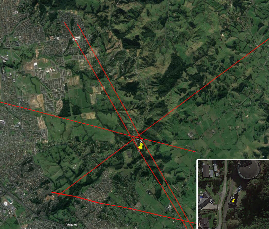
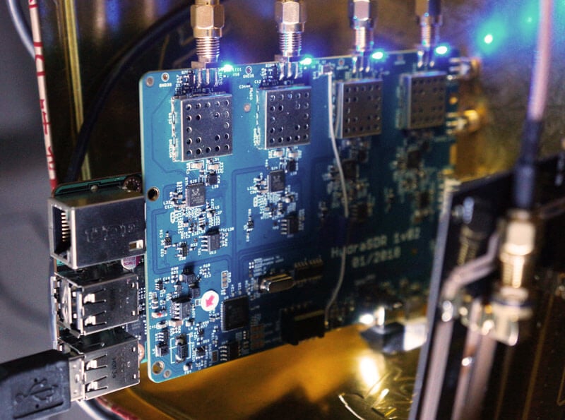
KerberosSDR pinpointing a transmitters location
KerberosSDR Prototype

Subscribe to our KerberosSDR Announcement

Please select all the ways you would like to hear from RTL-SDR Blog:

You can unsubscribe at any time by clicking the link in the footer of our emails. We use MailChimp as our marketing platform. By clicking below to subscribe, you acknowledge that your information will be transferred to MailChimp for processing. Learn more about MailChimp's privacy practices here.

KerberosSDR Running RF Direction Finding on a Tinkerboard

KerberosSDR (formerly HydraSDR) is our upcoming 4-input coherent RTL-SDR. It's designed for coherent applications like RF direction finding, passive radar, beam forming and more, but can also be used as a standard 4-channel SDR for monitoring multiple frequencies. In this post we demonstrate the direction finding application running on the TinkerBoard. 

Reminder: If you have any interest in KerberosSDR, please sign up to our KerberosSDR mailing list. Subscribers to this list will be the first to know when KerberosSDR goes on preorder, and the first 100 sales will receive a discounted price.

Subscribe to our KerberosSDR Announcement

Please select all the ways you would like to hear from RTL-SDR Blog:

You can unsubscribe at any time by clicking the link in the footer of our emails. We use MailChimp as our marketing platform. By clicking below to subscribe, you acknowledge that your information will be transferred to MailChimp for processing. Learn more about MailChimp's privacy practices here.

KerberosSDR Updates

This week we've managed to get the KerberosSDR demo software made by Tamás Peto functioning on a TinkerBoard. The TinkerBoard is a US$60 single board computer. It's similar to a Raspberry Pi 3, but more powerful. We've also tested the app running on the Raspberry Pi 3 and Odroid XU4. The Pi 3 is capable of running the software but it is a little slow, and the Odroid XU4 is a little faster than the TinkerBoard. In the future we hope to further optimize the code so even Raspberry Pi 3's will be smooth.

In the video below we used a circular array of four whip antennas connected to KerberosSDR. The TinkerBoard is connected to KerberosSDR and is set up to generate a WiFi hotspot, which we connect to with an Android phone and a Windows laptop. The Windows laptop connects to the TinkerBoard's desktop via VNC, and the Android phone receives an HTML/JavaScript based compass display via an Apache server running on the Tinkerboard. With this setup we can wirelessly control and view information from KerberosSDR and the TinkerBoard.

We've also tested the KerberosSDR system on a real signal, and have found it to work as expected. More demo's of that coming later.

For more info on KerberosSDR please see our previous announcement post.

KerberosSDR Direction Finding Test 2: Tinkerboard + Circular Array

KerberosSDR Prototype
KerberosSDR Prototype with TinkerBoard Running Computations

Using a Raspberry Pi 3, USB Soundcard, Speclab and Exagear to Detect SAQ VLF Transmissions

Thanks to DE8MSH for writing in about his project that involves using a Raspberry Pi 3 and cheap 7€ USB sound card connected to an old Grahn GS1 VLF antenna to detect the SAQ VLF station. Standard PC or USB sound cards can be used as a narrowband VLF capable SDR simply by connecting an antenna to the sound inputs. SAQ (aka Grimeton Radio Station) is a heritage VLF transmitter in Sweden that transmits CW at 17.2 kHz, normally only on Alexanderson Day and Christmas Day, but can sometimes unofficially transmit without announcement due to maintenance, training or local events.

In terms of software running on the Pi 3 DE8MSH uses Spectrum Laboratory (speclab) to monitor the sound card waterfall, and has written a Python script that uploads the processed images from speclab to a Twitter account every 20 minutes. This way he hopes to be able to detect any unannounced SAQ transmissions from his station in Sweden. 

Spectrum Laboratory is actually a Windows and x86 only program, however as shown in one of our previous posts, it is possible to use a special compatibility emulator called Exagear which allows you to run x86 programs on ARM hardware. Together with Wine you can then run x86 Windows programs on single board computers like the Raspberry Pi 3 which run Linux on ARM hardware.

Speclab Screenshot from DE8MSHs Pi3 soundcard monitoring system

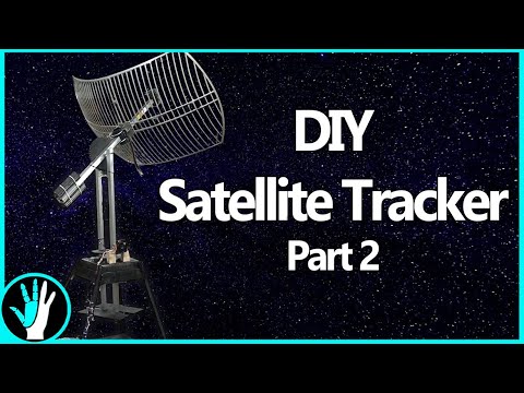
Building a Tracking Mount for HRPT Weather Satellite Reception Part 2

Earlier this month we posted about The Thought Emporium who uploaded a video to YouTube where they documented the first steps of their construction of a tracking mount for a 2.4 GHz grid WiFi dish which they intend to use for HRPT weather satellite reception.

If you didn't already know, receiving HRPT weather satellite signals is a little different to the more commonly received NOAA APT or Meteor M2 LRPT images which most readers may already be familiar with. HRPT is broadcast by the same NOAA satellites that provide the APT signal at 137 MHz, but is found in the L-band at around 1.7 GHz. The signal is much weaker, so a high gain dish antenna with motorized tracking mount, LNA and high bandwidth SDR like an Airspy is required. The payoff is that HRPT images are much higher in resolution compared to APT.

In this video they document the steps required to finish the physical build and add the electronics and motors required to control and move the dish. The final product is a working tracking mount that should be able to track the NOAA satellites as they pass over. In the next video which is not yet released they plan to actually test reception.

Track Satellites in Orbit - Part 2

Decoding a Moon Orbiting Satellite 378500 km’s away with an RTL-SDR

Thanks to IU2EFA (William) for writing in and letting us know about his success in decoding telemetry from the moon orbiting satellite known as DSLWP-B / LONGJIANG-2. LONJIANG-2 is a Chinese lunar microsatellite (45kg) that was launched in May 2018. It is designed to perform ultra long-wave radio astronomy observations. It also has an on board camera and took some nice photos of the Earth back in June.

While the satellite is still being tested, William notes that it is transmitting telemetry data to Earth during it's scheduled days at 435.4 MHz and 436.4 MHz, and the signal can be received with an RTL-SDR and Yagi antenna. William writes:

[LONJIAN-2] transmits with a little linear antenna and a little power of just 2 Watts.

In other sessions, I used a professional radio to have the maximum performance.

But this morning I wanted to test the reception, just using my RTLSDR V3 and my antenna yagi 15 elements pointed to the Moon. No other options (as filters, pre aplifiers, or other stuffs. Zero of these)

Well, the result was great. I received the signals and also i could decode them!

So I think people can be happy to know, that with a very little setup, they can receive incredible little signals from great distances.

When I received these signals, the Moon distance was about 378500 km.

LONGJIAN-2 transmits telemetry with GMSK and JT4G, and JT4G can be decoded with WSJT-X or WSJT 10. There is also a GNU Radio program called gr-dslwp that can be used to decode the telemetry. JT4G is a weak signal coding that can be decoded with signal levels down to -17 dB. Therefore anyone with modest hardware can decode the satellite. More information about the coding can be found on this post by Daniel Estevez.

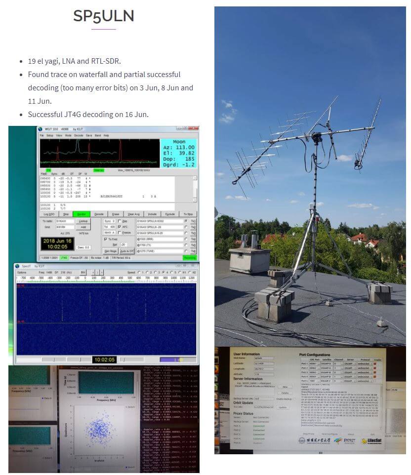
On the Lilacsat page for LONGJIANG-2 if you scroll down you can also see reports from several other amateur radio operators who have managed to receive the satellite with RTL-SDR dongles and other radios. Below is an image of an example for SP5ULN who was able to receive and decode the JT4G signal with an RTL-SDR, LNA, and 19-element Yagi.

Example of LONJIAN-2 being received with an RTL-SDR by SP5ULN as noted on the LilacSat website.
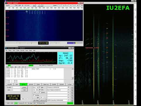
Ho Decodificato Segnali dalla LUNA! | Decoding a Satellite Orbiting the Moon (JT4G)

Receiving GOES Weather Satellite HRIT with an SDRplay and 2.4 GHz WiFi Grid Antenna

Over on the SDRplay forums member RSP2user has posted a new tutorial, this time showing how to receive weather satellite images from GOES satellites with an RSP2 and cheap 2.4 GHz WiFi grid antenna. 

GOES 15/16/17 are geosynchronous weather satellites that beam back high resolution weather  images and data. In particular they send beautiful high resolution 'full disk' images which show one side of the entire earth. As the satellites are in geosynchronous orbit, they are quite a bit further away from the earth. So compared to the more easily receivable low earth orbit satellites such as the NOAA APT and Meteor M2 LRPT satellites, a dish antenna, good LNA and possibly a filter is required to receive them. However fortunately, as they are in a geosynchronous orbit, the satellite is in the same position in the sky all the time, so no tracking hardware is required.

In the tutorial RSP2user notes that he's been using a $16 2.4 GHz WiFi grid dish antenna and the NooElec SAWbird LNA. In the past we've also seen GOES reception from Pieter Noordhuis who used a 1.9 GHz grid antenna from L-Com which seems to be a better match to the 1.7 GHz GOES frequency. However, 2.4 GHz WiFi grid antennas are much more common and therefore much cheaper. In the past there has been debate on whether or not these cheaper WiFi antennas would be good enough for GOES, so it's good to see that the cheaper option is confirmed to work, at least for the satellite elevations found in the RSP2user's part of the USA.

The SAWBird is a 1.7 GHz LNA which is required to improve SNR by reducing system noise figure, and to filter any interfering out of band signals. The SAWbird is currently not available for public sale, but NooElec have noted that it is due to be released soon. RSP2user also notes that the polarization of the dish is important, so the dish may need to be rotated, and also that flipping the secondary reflector significantly increases the gain at 1.69 GHz.

For software the XRIT demodulator from USA-Satcom for a small fee is used together with the SDRplay RSP2. As seen by Pieter Noordhuis' results, it's also possible to receive these signals with an RTL-SDR and Pieters free software. So it may be possible to reduce the costs of a GOES reception system by using an RTL-SDR, SAWBird and 2.4 GHZ WiFi grid antenna. With those components the total cost would be well under $100.

As a bonus, in later posts on his forum thread, RSP2user shows that the system can also be used to receive HRPT images from the low earth orbit NOAA 19 satellite by hand tracking the antenna as the satellite passes over.

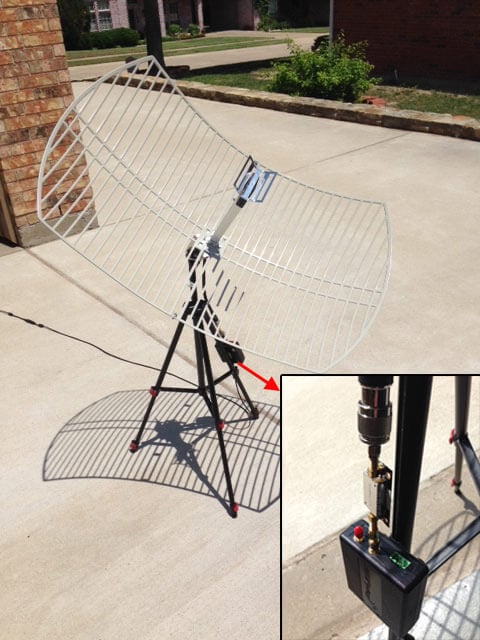
RSP2users GOES Receiver: SDRplay, SAWBird LNA, 2.4 GHz WiFi Grid Antenna

Building a Tracking Mount for HRPT Weather Satellite Reception

Over on YouTube channel The Thought Emporium recently released a new video where they show the first steps they've taken towards building a home made satellite tracking mount for receiving HRIT and HRPT low earth orbit weather satellites. In their build they use a 2.4 GHz WiFi parabolic grid antenna, gears and mounts made from milled wood, and some metal supports. The build is not yet finished, but they intend to show their progress in future videos. Note that we're not confident that the 2.4 GHz grid antenna will actually work for them. In the past people have had success with 1.9 GHz Grid antennas however.

If you didn't already know, receiving HRPT weather satellite signals is a little different to the more commonly received NOAA APT or Meteor M2 LRPT images which most readers may already be familiar with. HRPT is broadcast by the same NOAA satellites that provide the APT signal at 137 MHz, but is found in the L-band at around 1.7 GHz. The signal is much weaker, so a high gain dish antenna with motorized tracking mount, LNA and high bandwidth SDR like an Airspy is required. The payoff is that HRPT images are much higher in resolution compared to APT.

Actually, it's not entirely true that a tracking mount is required, although it certainly makes things easier. We've seen in the past that 'Tysonpower' was able to receive HRPT by tracking his dish by hand.

The Thought Emporium also note that they hope to use their tracking mount in the future for other purposes like amateur radio astronomy. In one of their previous experiments they've build a smaller version which was able to create a heat map of WiFi signal strengths in their area.

Tracking Satellites in Orbit - Part 1

An Opensource Mini-Whip Antenna and Upconverter Design for RTL-SDRs

Thank you to Igor Yatsevich for submitting news about an open source Mini-Whip and Upconverter design that he's created and released for free on GitHub. An upconverter converts HF frequencies into VHF frequencies so that they can be received by RTL-SDRs in their quadrature mode, and a Mini-Whip is a small active antenna for receiving HF signals.

The designs include the PCB Gerber files for manufacturing, the components list and assembly and usage guides. Also both through-hole and SMD designs are provided.

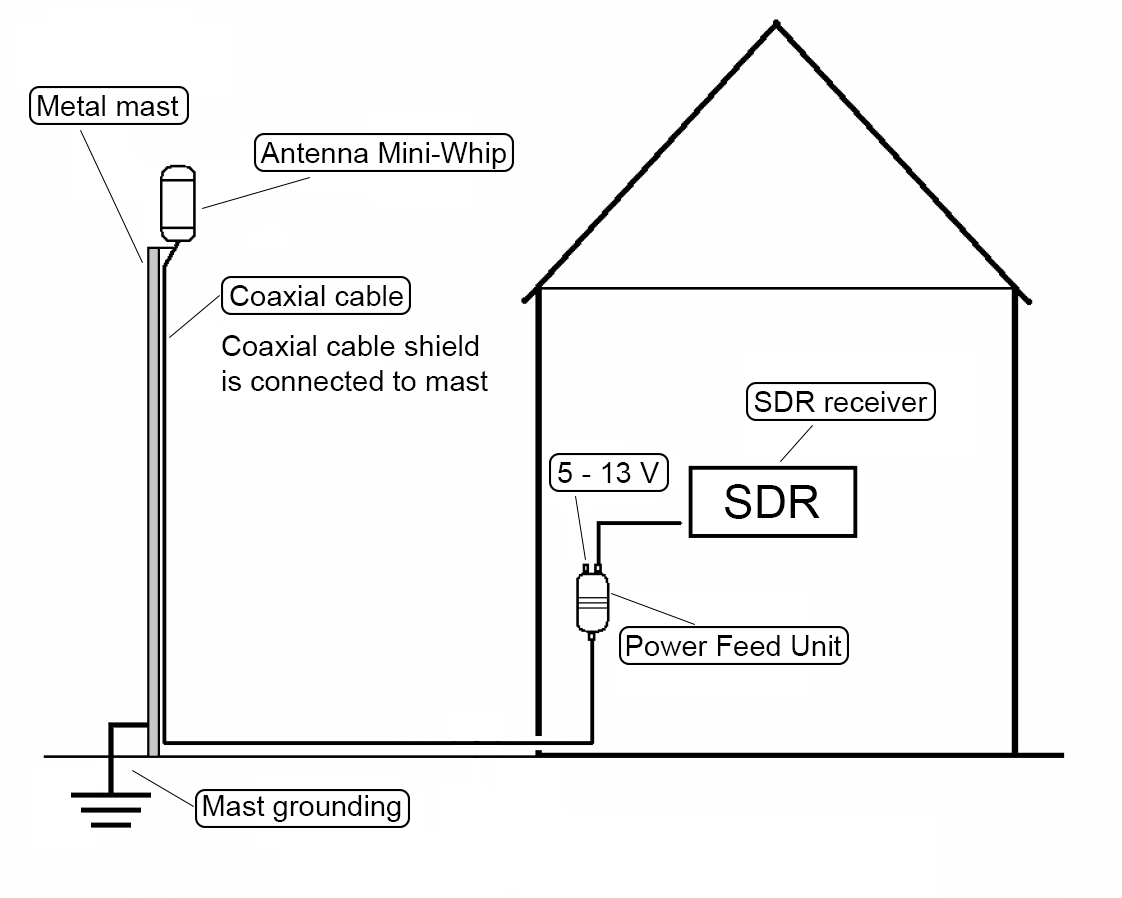
The Mini-Whip design has a frequency range of 10 kHz - 30 MHz and to power it you'll need a 5 - 13V bias tee. You will need to install it up high and preferably away from the house as Mini-Whips are quite susceptible to local noise pickup. Another very important point is that Mini-Whips need to have a good ground connection. The upconverter is based on the ADE-1 mixer, and uses a 125 MHz local oscillator.

Igor's documentation on the project is excellent, and is a good read for getting more information about upconverters and Mini-Whips. He has noted that he is sending us some samples of units that he's built, so when we receive them we'll post again with test results. It looks as if he's put a lot of research into these designs so we're looking forward to seeing how well they work. 

Diagram on how to ground a miniwhip connected to a metal mast.
Diagram from Igor's documentation about how to properly ground a Mini-Whip connected to a metal mast.