Back in January we posted about a Vivaldi antenna project by "hexandflex". In that project he showed how he designed and manufactured the Vivaldi. A Vivaldi antenna is wideband and directional and the design works well for frequencies above 800 MHz, but becomes too physically large to handle for lower frequencies like 400 MHz. In his latest project, hexandflex has designed a PCB based spiral antenna to cover these lower frequencies.
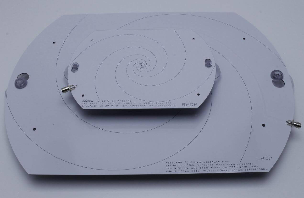
Hexandflex is currently selling his spiral antennas over on Tindie. There are two versions, one smaller one costing $32 designed for 800 MHz+ and a larger one costing $42 designed for 300 MHz+. Both come with suction cups that allow for easy window mounting.
The 800 MHz+ and 300 MHz+ spiral antennas by Hexandflex
RPiTX is software for the Raspberry Pi which can turn it into a 5 kHz to 1500 MHz transmitter which can transmit any arbitrary signal. In order to transmit the software does not require any additional hardware apart from a wire plugged into a GPIO pin on the expansion header. It works by modulating the GPIO pin with square waves in such a way that the desired signal is generated. However, although additional hardware isn't required, if RPiTX is to be used in any actual application a band-pass filter is highly recommended in order to remove any harmonics which could interfere and jam other radio systems.
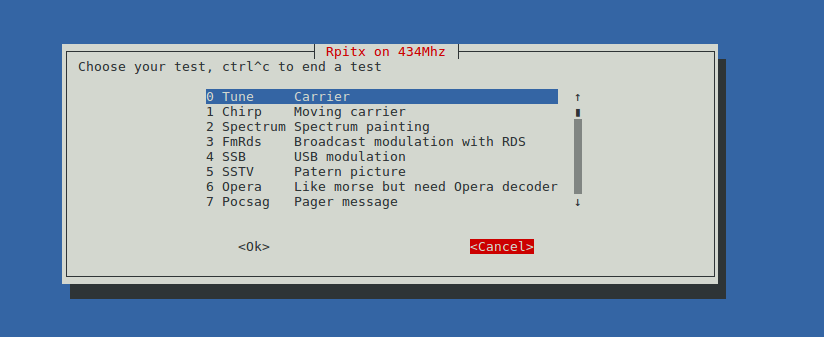
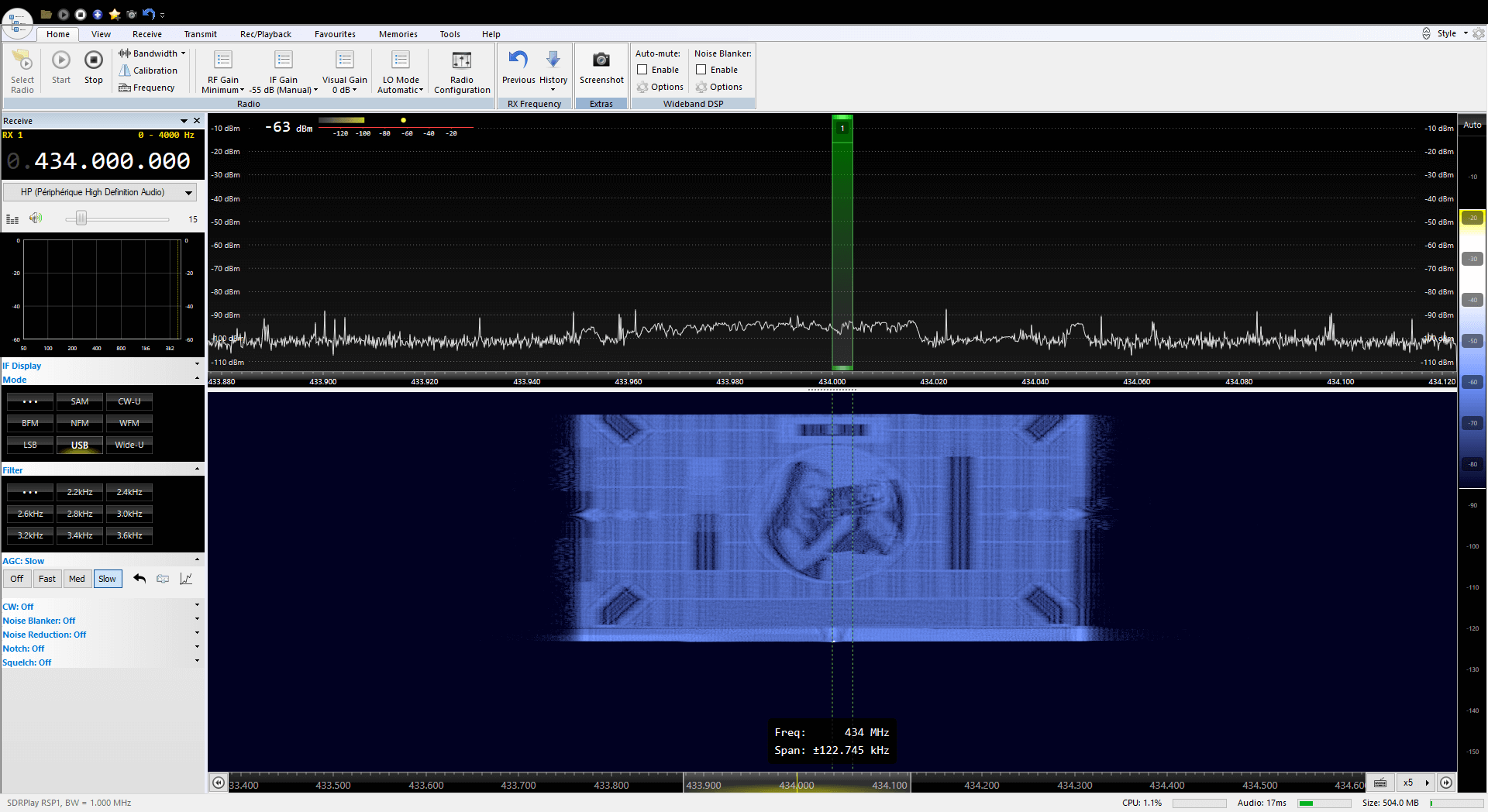
Earlier this month RPiTX was upgraded to version 2. One of the changes is a new GUI for testing the various transmission modes. Currently it is possible to transmit a chirp, FM with RDS, USB, SSTV, Opera, Pocsag, SSTV, Freedv. There is also a spectrum painter which allows you to display an image on a SDR's waterfall.
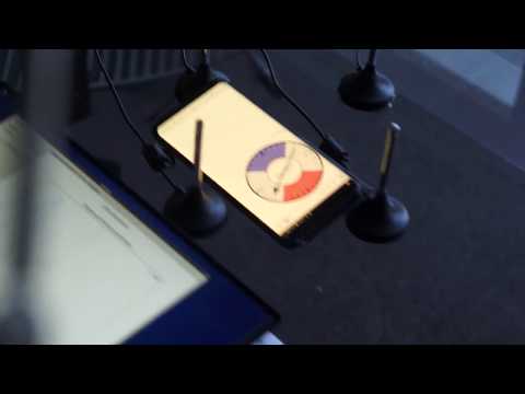
The RPiTX V2 GUIPainting an Image on a SDR Waterfall Display with RPiTX v2
The RPiTX v2 update also makes recording a signal with an RTL-SDR, and replaying that signal with RPiTX significantly easier. Previously it was necessary to go through a bunch of preprocessing steps (as described in our previous tutorial) in order to get a transmittable file, but now RPiTX is capable of transmitting a recorded IQ file directly. This makes copying things like 433 MHz ISM band remotes significantly easier. One application might be to use RPiTX as an internet connected home automation tool which could control all your wireless devices.
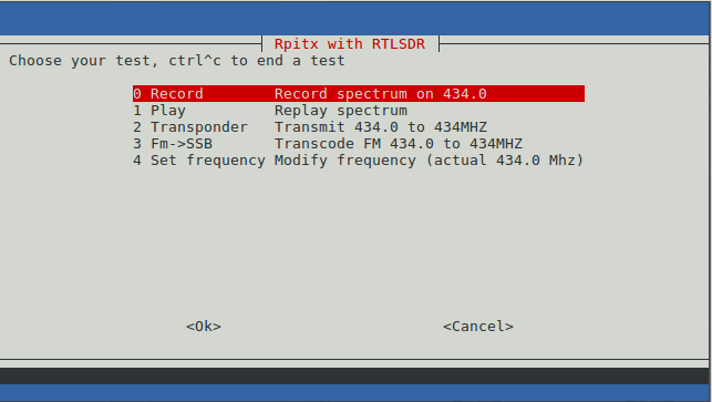
Finally, another application of the RPiTX and RTL-SDR combination is a live RF relay. The software is able to receive a signal at one frequency from the RTL-SDR, and then re-transmit it at another frequency in real time. Additionally, it is also capable of live transmodulation, where it receives an FM radio station, demodulates and then remodulates it as SSB to transmit on another frequency.
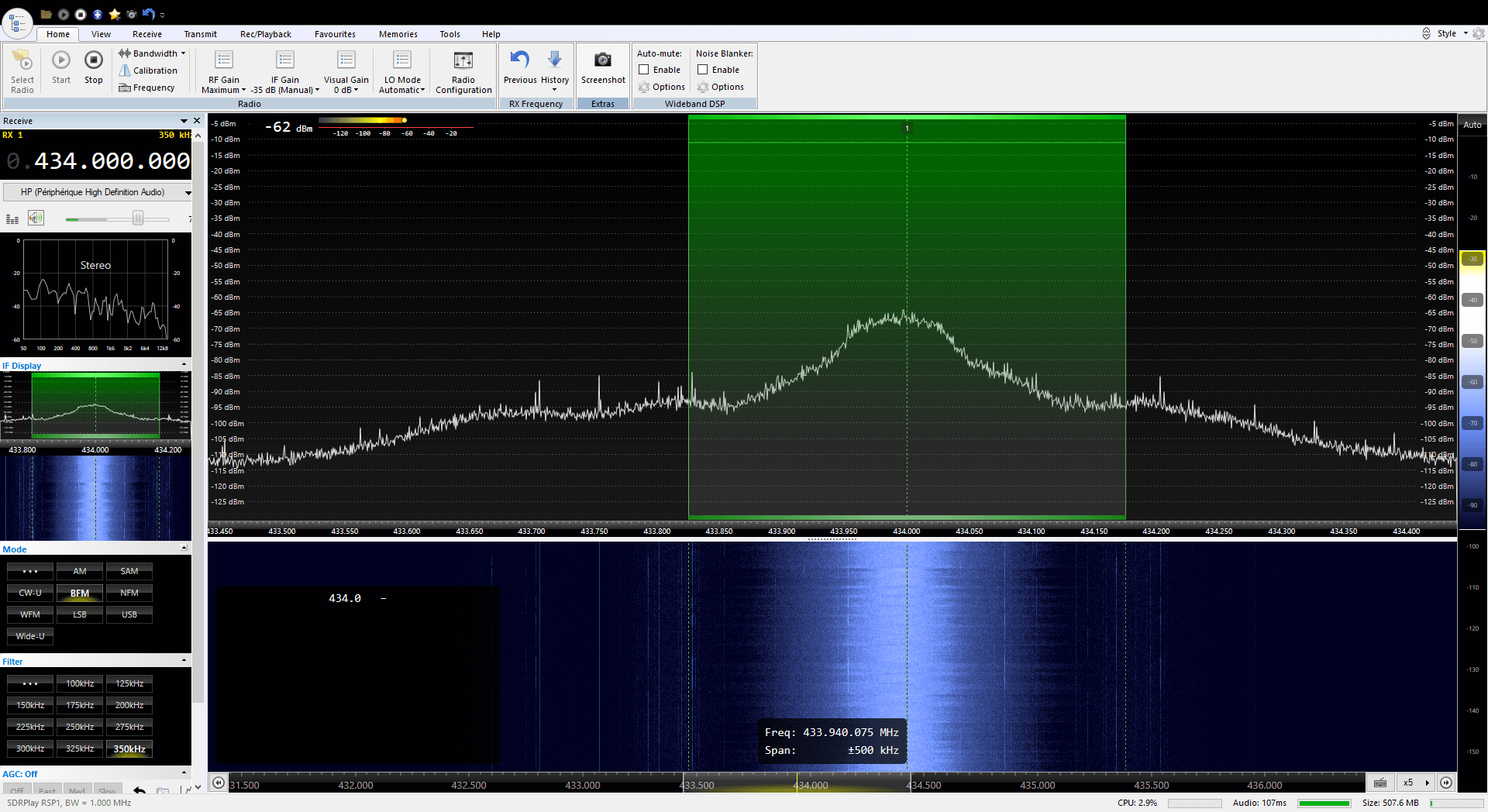
The RPiTX V2 RTL-SDR MenuRPiTX v2 re-transmitting a broadcast FM signal live at 434 MHz.
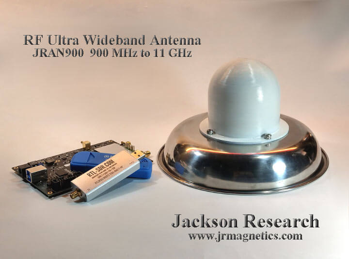
John required a wideband antenna that could cover the cellphone bands, WiFi, Bluetooth up to 6 GHz and the new USB band from 5 GHz to 10 GHz all in a single antenna installation. He also needed the impedance to be as flat as possible to reduce signal pulse distortion. First he looked into classic discone and sphere antenna designs, but found that while a sphere had the required bandwidth, it did not have the desired impedance characteristics, and a discone had the desired impedance characteristics, but not the ultra wide bandwidth required.
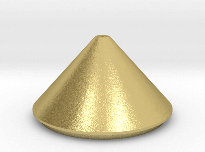
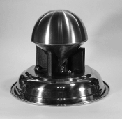
To get around this John combines the sphere and discone designs together to create a sort of icecream with cone looking shape. This results in the ultra wide bandwidth required, and a relatively flat SWR that stays below 2.
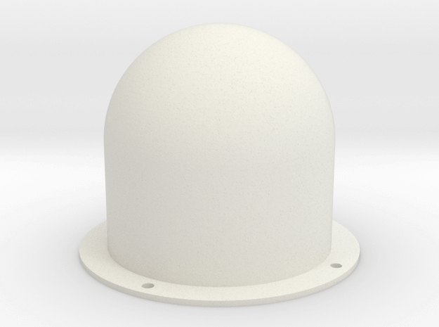
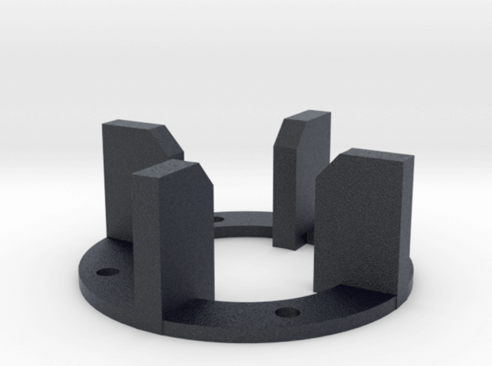
The design is easily reproducible by anyone with a metal 3D printer. The antenna's top hemisphere and cone are printed in brass, whilst the radome and supporting structure are printed in plastic.
Back in January we posted about a Vivaldi antenna project by "hexandflex". In that project he showed how he designed and manufactured the Vivaldi. A Vivaldi antenna is wideband and directional and the design works well for frequencies above 800 MHz, but becomes too physically large to handle for lower frequencies like 400 MHz. In his latest project, hexandflex has designed a PCB based spiral antenna to cover these lower frequencies.
Hexandflex is currently selling his spiral antennas over on Tindie. There are two versions, one smaller one costing $32 designed for 800 MHz+ and a larger one costing $42 designed for 300 MHz+. Both come with suction cups that allow for easy window mounting.
The 800 MHz+ and 300 MHz+ spiral antennas by Hexandflex
RPiTX is software for the Raspberry Pi which can turn it into a 5 kHz to 1500 MHz transmitter which can transmit any arbitrary signal. In order to transmit the software does not require any additional hardware apart from a wire plugged into a GPIO pin on the expansion header. It works by modulating the GPIO pin with square waves in such a way that the desired signal is generated. However, although additional hardware isn't required, if RPiTX is to be used in any actual application a band-pass filter is highly recommended in order to remove any harmonics which could interfere and jam other radio systems.
Earlier this month RPiTX was upgraded to version 2. One of the changes is a new GUI for testing the various transmission modes. Currently it is possible to transmit a chirp, FM with RDS, USB, SSTV, Opera, Pocsag, SSTV, Freedv. There is also a spectrum painter which allows you to display an image on a SDR's waterfall.
The RPiTX V2 GUIPainting an Image on a SDR Waterfall Display with RPiTX v2
The RPiTX v2 update also makes recording a signal with an RTL-SDR, and replaying that signal with RPiTX significantly easier. Previously it was necessary to go through a bunch of preprocessing steps (as described in our previous tutorial) in order to get a transmittable file, but now RPiTX is capable of transmitting a recorded IQ file directly. This makes copying things like 433 MHz ISM band remotes significantly easier. One application might be to use RPiTX as an internet connected home automation tool which could control all your wireless devices.
Finally, another application of the RPiTX and RTL-SDR combination is a live RF relay. The software is able to receive a signal at one frequency from the RTL-SDR, and then re-transmit it at another frequency in real time. Additionally, it is also capable of live transmodulation, where it receives an FM radio station, demodulates and then remodulates it as SSB to transmit on another frequency.
The RPiTX V2 RTL-SDR MenuRPiTX v2 re-transmitting a broadcast FM signal live at 434 MHz.
John required a wideband antenna that could cover the cellphone bands, WiFi, Bluetooth up to 6 GHz and the new USB band from 5 GHz to 10 GHz all in a single antenna installation. He also needed the impedance to be as flat as possible to reduce signal pulse distortion. First he looked into classic discone and sphere antenna designs, but found that while a sphere had the required bandwidth, it did not have the desired impedance characteristics, and a discone had the desired impedance characteristics, but not the ultra wide bandwidth required.
To get around this John combines the sphere and discone designs together to create a sort of icecream with cone looking shape. This results in the ultra wide bandwidth required, and a relatively flat SWR that stays below 2.
The design is easily reproducible by anyone with a metal 3D printer. The antenna's top hemisphere and cone are printed in brass, whilst the radome and supporting structure are printed in plastic.
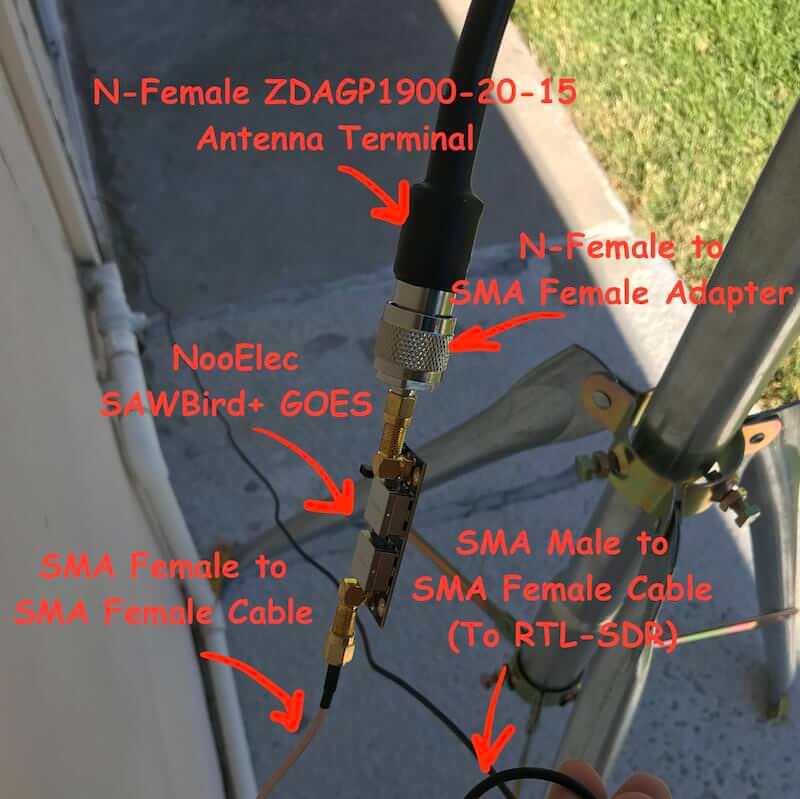
Aleksey Smolenchuk (lxe) has recently uploaded a step-by-step guide to setting up a GOES weather satellite receiver with an RTL-SDR dongle, Raspberry Pi and the goestools software. GOES 15/16/17 are geosynchronous weather satellites that beam high resolution weather images and data. In particular they send beautiful 'full disk' images which show one side of the entire earth. Compared to the more familiar and easier to receive low earth orbit satellites such as NOAA APT and Meteor M2 LRPT, the geosynchronous GOES satellites require slightly more effort as you need to set up a dish antenna, use a special LNA, and install Linux software.
Aleksey's tutorial first shows where to purchase the required hardware and notes that the total cost of the system is around $185. Next he goes on to show the hardware connection order, and then how to install and configure the goestools decoding software onto a Raspberry Pi.
FPV stands for 'First Person View', and is a term used to describe the hobby of flying remote controlled aircraft entirely via the view from a wireless camera that transmits live video to the pilots screen or video goggles.
Part of the FPV hobby is to not only enjoy flying, but also to tweak the wireless video equipment for maximum range and reliability. This involves measuring the SWR characteristics of FPV antennas. SWR is a metric that describes how well the impedance of an antenna is matched with the receiver at a certain frequency. Poor SWR results in additional signal loss on top of cable and connector loss. We note that SWR is only one antenna metric, and doesn't take into account radiation pattern and antenna gain which is often more important, but it is the easiest metric to measure and control, and should give you some idea as to if an antenna was designed and tuned properly.
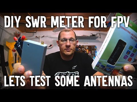
As FPV hobbyists are often not hams or radio professionals, most don't have access to the equipment required to measure SWR. So over on his YouTube channel bonafidepirate shows how he's been using a cheap RTL-SDR, noise source and RF Bridge to measure the SWR of his FPV antennas. The process is similar to the one shown in our tutorial, but he uses the Spektrum software which allows you to measure SWR entirely within the software itself.
In the video bonafidepirate goes over the required hardware, software and the setup, and then demonstrates several SWR scans of different FPV antennas.
On The Thought Emporium YouTube channel a new video has been uploaded showing the full disk images of the earth that they've been able to receive from GOES geosynchronous weather satellites. Over the past couple of years GOES satellite reception has become much easier for hobbyists to achieve with the release of the NooElec SAWbird LNA+Filter, information on how to use a cheap 2.4 GHz WiFi grid antenna for reception and the release of free open source decoder software. It was also shown that an RTL-SDR dongle is sufficient for receiving these images as well. With all these new developments it is now possible to build a GOES receiving station for under $100.
The Thought Emporium video blurb reads:
In the fall of 2016 I saw my first rocket launch and little did I know that the satellite on that rocket would come to shape and fill my thoughts for many years. We're no strangers to getting data out of space on this channel, but GOES-16 is special, and not just because I was there when it left earth. Unlike the satellites we looked at in the past, GOES is in geostationary orbit and has an amazing suite of cameras and sensors on board. While it's a bit harder to receive data from GOES the extra effort is absolutely worth it, especially because it can see then entire globe all at once and send out those images in stunning high resolution. And it even comes with the added bonus of rebroadcast data from other satellites giving us a view of the opposite side of the planet as well.
In this video we go through the hardware and software needed to receive these gorgeous images and what is contained in the signals we receive.
Pulling Clear Images Directly Off Satellites | GOES-15,16,17 and Himawari 8 HRIT
KerberosSDR is our upcoming low cost 4-tuner coherent RTL-SDR. With four antenna inputs it can be used as a standard array of four individual RTL-SDRs, or in coherent applications such as direction finding, passive radar and beam forming. More information can be found on the KerberosSDR main post. Please remember to sign up to our KerberosSDR mailing list on the main post or at the end of this post, as subscribers will receive a discount coupon valid for the first 100 pre-order sales. The list also helps us determine interest levels and how many units to produce.
In this post we'll show an experiment that we performed which was to pinpoint the location of a transmitter using KerberosSDR's coherent direction finding capabilities. RF direction finding is the art of using equipment to determine the location of a transmitting signal. The simplest way is by using a directional antenna like a Yagi to try and determine the bearing based on signal strength. Another method is using a pseudo-doppler or coherent array of antennas to determine a bearing based on phase information.
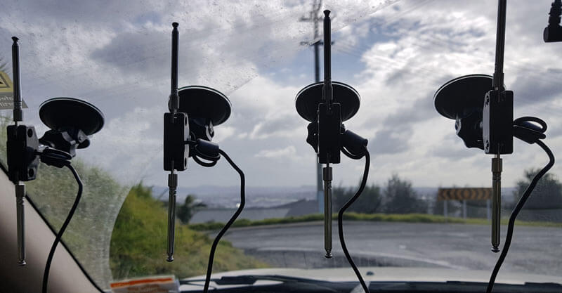
For the test we tuned the KerberosSDR RTL-SDRs to listen to a signal at 858 MHz and then drove to multiple locations to take direction readings. The antennas were set up as a linear array of four dipole antennas mounted on the windshield of a car. To save space, the dipoles were spaced at approximately a 1/3 the frequency wavelength, but we note that optimal spacing is at half a wavelength. The four dipole antennas were connected to KerberosSDR, with a laptop running the direction finding demo software.
Low cost direction finding array mounted to vehicle windshield.
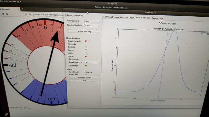
Our open source demo software (to be released later when KerberosSDR ships) developed by Tamás Peto gives us a graph and compass display that shows the measured bearing towards the transmitter location. The measured bearing is relative to the antenna array, so we simply convert it by taking the difference between the car's bearing (determined approximately via road direction and landmarks in Google Earth) and the measured bearing. This hopefully results in a line crossing near to the transmitter. Multiple readings taken at different locations will end up intersecting, and where the intersection occurs is near to where the transmitter should be.
KerberoSDR SDR Directing Finding DOA Reading
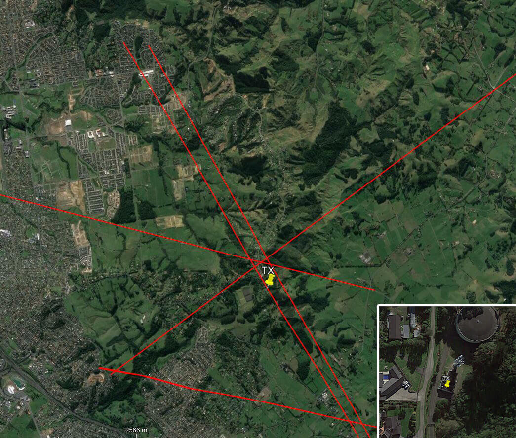
In the image below you can see the five bearing measurements that we made with KerberosSDR. Four lines converge to the vicinity of the transmitter, and one diverges. The divergent reading can be explained by multipath. In that location the direct path to the transmitter was blocked by a large house and trees, so it probably detected the signal as coming in from the direction of a reflection. But regardless with four good readings it was possible to pinpoint the transmitting tower to within 400 meters.
In the future we hope to be able to automate this process by using GPS and/or e-compass data to automatically draw bearings on a map as the car moves around. The readings could also be combined with signal strength heatmap data for improved accuracy.
This sort of capability could be useful for finding the transmit location of a mystery signal, locating a lost beacon, locating pirate or interfering transmitters, determining a source of noise, for use during fox hunts and more.
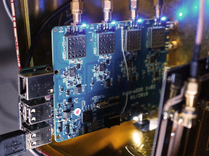
KerberosSDR pinpointing a transmitters locationKerberosSDR Prototype
KerberosSDR (formerly HydraSDR) is our upcoming 4-input coherent RTL-SDR. It's designed for coherent applications like RF direction finding, passive radar, beam forming and more, but can also be used as a standard 4-channel SDR for monitoring multiple frequencies. In this post we demonstrate the direction finding application running on the TinkerBoard.
Reminder: If you have any interest in KerberosSDR, please sign up to our KerberosSDR mailing list. Subscribers to this list will be the first to know when KerberosSDR goes on preorder, and the first 100 sales will receive a discounted price.
KerberosSDR Updates
This week we've managed to get the KerberosSDR demo software made by Tamás Peto functioning on a TinkerBoard. The TinkerBoard is a US$60 single board computer. It's similar to a Raspberry Pi 3, but more powerful. We've also tested the app running on the Raspberry Pi 3 and Odroid XU4. The Pi 3 is capable of running the software but it is a little slow, and the Odroid XU4 is a little faster than the TinkerBoard. In the future we hope to further optimize the code so even Raspberry Pi 3's will be smooth.
In the video below we used a circular array of four whip antennas connected to KerberosSDR. The TinkerBoard is connected to KerberosSDR and is set up to generate a WiFi hotspot, which we connect to with an Android phone and a Windows laptop. The Windows laptop connects to the TinkerBoard's desktop via VNC, and the Android phone receives an HTML/JavaScript based compass display via an Apache server running on the Tinkerboard. With this setup we can wirelessly control and view information from KerberosSDR and the TinkerBoard.
We've also tested the KerberosSDR system on a real signal, and have found it to work as expected. More demo's of that coming later.