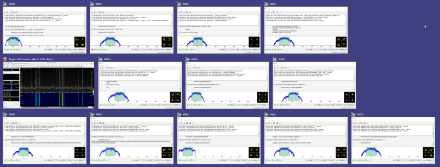
In a post uploaded last month we noted that Outernet was selling off some of their old L-Band satellite antennas cheaply. Nils Schiffhauser (DK8OK) decided to take advantage of the sale and bought one. Now Nils has created a blog post that shows how he's been able able to decode 12 L-Band AERO channels simultaneously with the Outernet L-band antenna, an Airspy R2 and SDR-Console V3. AERO is the satellite based version of aircraft ACARS, and it's L-band signals contain short ground to air messages like weather reports and flight plans. Multiple channels are often in use at any one time.
To achieve this Nils uses the multi-channel tuning capabilities of SDR-Console V3, which allows him to open up 12-channels, each tuned to a different AERO frequency. He then opens up 12 instances of the AERO decoder known as JAERO, and then uses VB-Cable to pipe the audio from each channel into a JAERO instance. Nils writes that the key to making JAERO run with multiple instances is to install JAERO into different folders on your PC, and give each JAERO.exe a unique file name like JAERO_1.exe.
He collects all the data into a program called Display Launcher and Nils notes that the whole set up has been stable digesting 54,000 messages over the last 24 hours.
Cubesats are small shoebox sized satellites that are usually designed by universities or amateur radio organizations for basic space experiments or amateur radio communications. Typically they have an orbit lifespan of only 3-6 months.
Cubesats typically transmit signals at around 435 MHz, and they are powerful enough to be received with a simple home made antenna and an RTL-SDR. To help with this Thomas N1SPY has created a YouTube video where he shows exactly how to construct a cheap eggbeater antenna made out of a few pieces of copper wire and an SO-239 UHF connector. Later in the video he demonstrates some Cubesats being received with his antenna, an RTL-SDR and the SDR-Console V3 software.
2018: Thomas N1SPY chases mini satellites on a budget
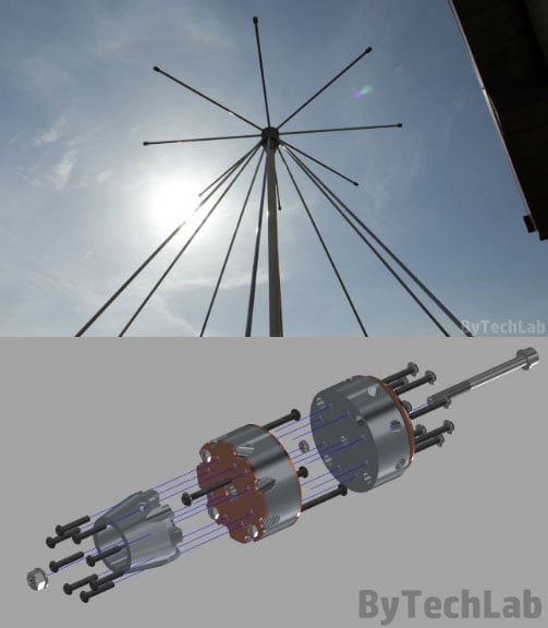
Over on his blog author ByTechLab has posted about his 'mostly 3D printed' discone antenna. A discone is a type of wideband antenna, so it is commonly used with SDRs like the RTL-SDR that have huge frequency ranges. Building a discone can be difficult, but ByTechLab shows that with a 3D printer it is possible to print the aluminum rod mounts, which significantly reduces construction complexity. His post shows the exact directions, and the stl files are available over on Thingiverse.
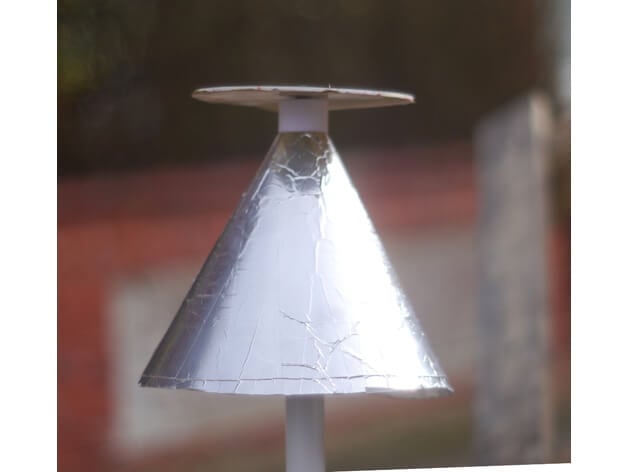
Note that back in March we saw another 3D printed discone by mkarliner that used a full cone design with the cone being made out of aluminum tape. Discones based on aluminum rods should however be more weather resistant, and more able to withstand wind loads, so ByTechLab's design is more suitable for permanent outdoor mounting.
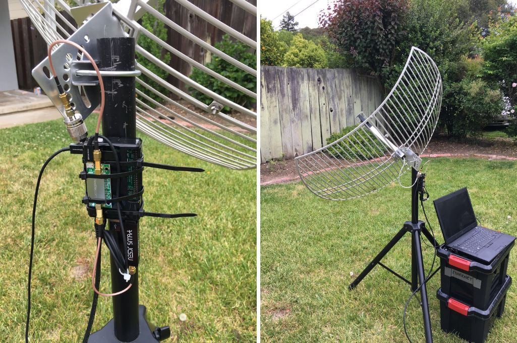
Over on Twitter and his github.io page, Pieter Noordhuis (@pnoordhuis) has shared details about his low cost RTL-SDR based GOES satellite receiving setup. GOES 15/16/17 are geosynchronous weather satellites that beam back high resolution weather images and data. In particular they send beautiful high resolution 'full disk' images which show one side of the entire earth. As the satellites are in geosynchronous orbit, they are quite a bit further away from the earth. So compared to the more easily receivable low earth orbit satellites such as the NOAA APT and Meteor M2 LRPT satellites, a dish antenna, good LNA and possibly a filter is required to receive them. However fortunately, as they are in a geosynchronous orbit, the satellite is in the same position in the sky all the time, so no tracking hardware is required.
In the past we've seen people receive these images with higher end SDRs like the Airspy and SDRplay. However, Pieter has shown that it is possible to receive these images on a budget. He uses an RTL-SDR, a 1.9 GHz grid dish antenna from L-Com, a Raspberry Pi 2, the NooElec 'SAWBird' LNA, and an additional SPF5189Z based LNA. The SAWBird is a yet to be released product from NooElec. It is similar to their 1.5 GHz Inmarsat LNA, but with a different SAW filter designed for 1.7 GHz GOES satellites. The total cost of all required parts should be less than US $200 (excluding any shipping costs).
Pieter also notes that he uses the stock 1.9 GHz feed on the L-com antenna, and that it appears to work fine for the 1.7 GHz GOES satellite frequency. With this dish he is able to receive all three GOES satellites at his location with the lowest being at 25 degrees elevation. If the elevation is lower at your location he mentions that a larger dish may be required. It may be possible to extend the 1.9 GHz L-Band dish for better reception with panels from a second cheaper 2.4 GHz grid dish, and this is what @scott23192 did in his setup.
For software Pieter uses the open source goestools software that Pieter himself developed. The software is capable of running on the Raspberry Pi 2 and demodulating and decoding the signal, and then fully assembling the decoded signal into files and images.
A Discone is a type of antenna that is designed to be resonant over a wide range of frequencies. Most antenna designs only really receive well on a few resonant frequencies, but a Discone is resonant over a much wider frequency range. This makes it a good partner for RTL-SDR and other SDR units as many SDRs tend to have wide tunable frequency ranges. With a wideband antenna like a Discone connected to an RTL-SDR one can scan over the almost entire tunable frequency range without needing to change antennas for each band. The drawbacks to a Discone however is that the antenna gain is not very high, and that it makes the SDR more susceptible to out of band interference. They also tend to be fairly expensive and difficult to build.
The Discone antenna is remarkable in that it is capable of receiving and transmitting over a wide range of frequencies with good matching. Because of this, it is a good match for SDR receivers such as the popular RTL-SDR sticks.
The only really tricking thing about making a discone is that the disc has to be balanced at the very top of the cone, which is mechanically awkward.
The two parts here allow the cone to be solidly clamped and provide an adequate base for the disk. There also two holes for bring the coax centre and braid out to the disc and cone. The base part has a socket at the bottom for 25mm (1 inch) plastic conduit for mounting
This antenna illustrated is designed for 400MHz and up, and as such transmits well on the 70cms amateur band, US and UK PMR channels and 23cms. It also receives aircraft ADS-B signals very well. I used .3mm plastic sheet for the cone and 2mm plastic for the disc, and then covered them with aluminium weatherproof tape. Be sure to check for continuity across the tape stripes.
The screenshot is of a calculator by VE3SQB which can be downloaded from http://www.ve3sqb.com/ if you want to make attenna's for other ranges.
A 3D Printed Discone
If you're interested in building wideband antenna there is also the planar disk antenna (pdf) which can be built out of pizza pans.
Over on the swling.com blog admin Thomas has been exploring various indoor antenna options for pairing with an HF capable software defined radio. He notes that unless you happen to live in isolation, you're highly likely to experience RFI problems with standard wire antennas. Instead he recommends looking into magnetic loop antennas which are significantly more resistant to urban electric field based RFI noise, and they can also be rotated to null out any other local noise sources. Thomas then goes on to highlight some of the best commercial magnetic loop options for sale. There is also some good advice in the comments section.
We note that magnetic loop antenna seem to work fairly well with the RTL-SDR in V3 in direct sampling mode, but you may need to filter out the broadcast AM band to avoid overload if the loop doesn't do this already.
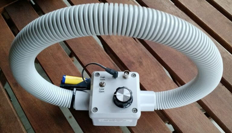
An example small PK-Loop antenna for receiving shortwave with an SDR.
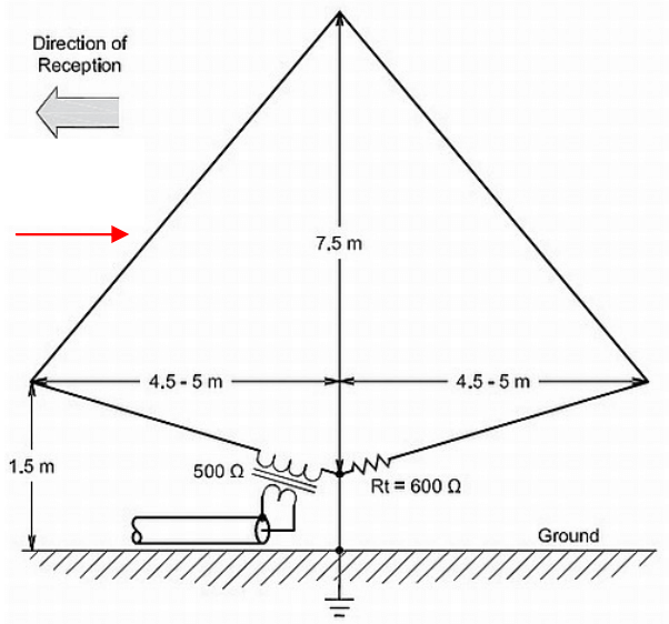
Thank you to Frank Sessink (PA0FSB) for submitting to us his document describing the K9AY loop antenna (pdf), which is the antenna that he successfully uses with his RTL-SDR for HF reception. The antenna combines magnetic (H) and electric (E) field reception in order to create a directive radiation pattern. Frank extends the idea by showing a method that can adjust the directivity electrically with some simple resistor switching.
The antenna that I use is for medium wave DX, specially to receive MW from USA here in Europe/The Netherlands. The antenna is a combination of a magnetic loop and a sense antenna for the E-field. The magnetic loop is directive, but has no front-rear ratio. The E-field antenna has omnidirectional sensitivity. The combination, in correct phase and amplitude, results in a front-rear ratio of more than 25 dB over the frequency range from 500 kHz to around 3 MHz. Higher frequency makes no sense, since skywave signals distort the ground wave directivity pattern.
A simple modification is used as directional antenna with remote control: two orthogonal loops that combine E and H-field in a simple way. I can make 8 selectable directions.
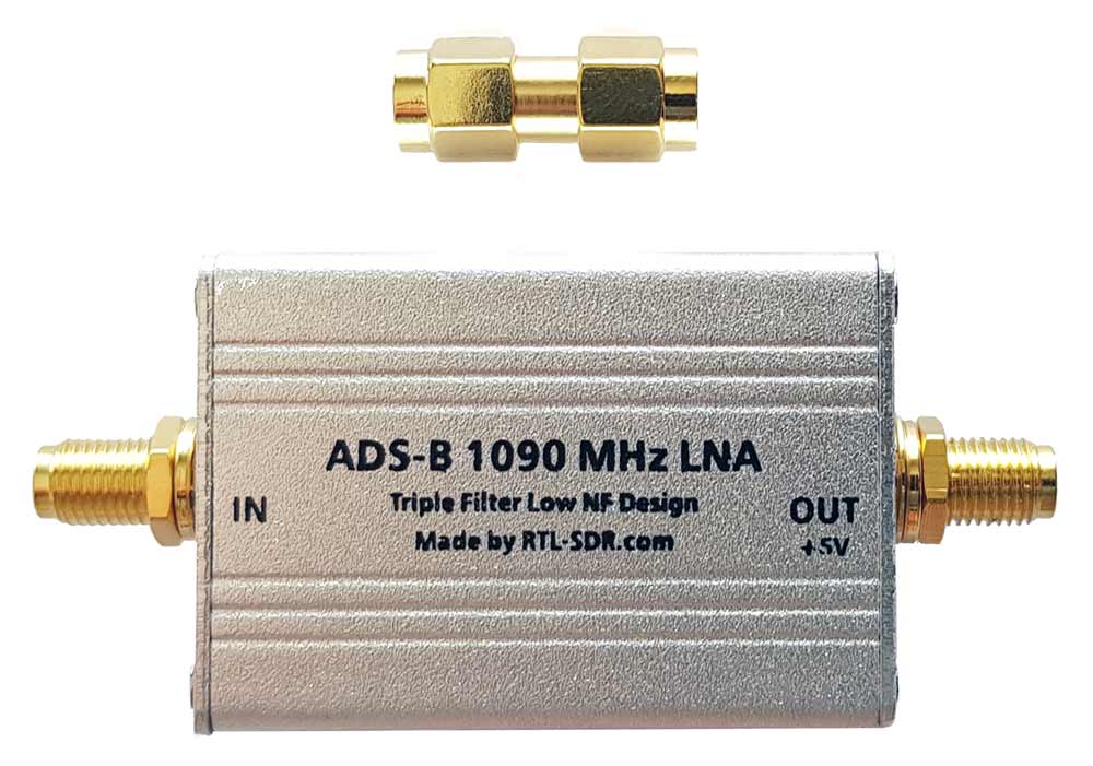
We're happy to announce the release of our new high performance low noise amplifier (LNA) for improving 1090 MHz ADS-B reception. The LNA uses a low noise figure high linearity two stage MGA-13116 amplifier chip and three stages of filtering to ensure that strong signals or interference will not overload either the amplifier or SDR dongle.
The LNA is currently only available from our Chinese warehouse, and costs US$24.95 including shipping. Please note that the price may increase slightly in the future, and that Amazon USA may not be stocked until March.
An LNA can help improve ADS-B reception by reducing the noise figure of the system and by helping to overcome losses in the coax cable and/or any other components such as switches and connector in the signal path. To get the best performance from an LNA, the LNA needs to be positioned close to the antenna, before the coax to the radio.
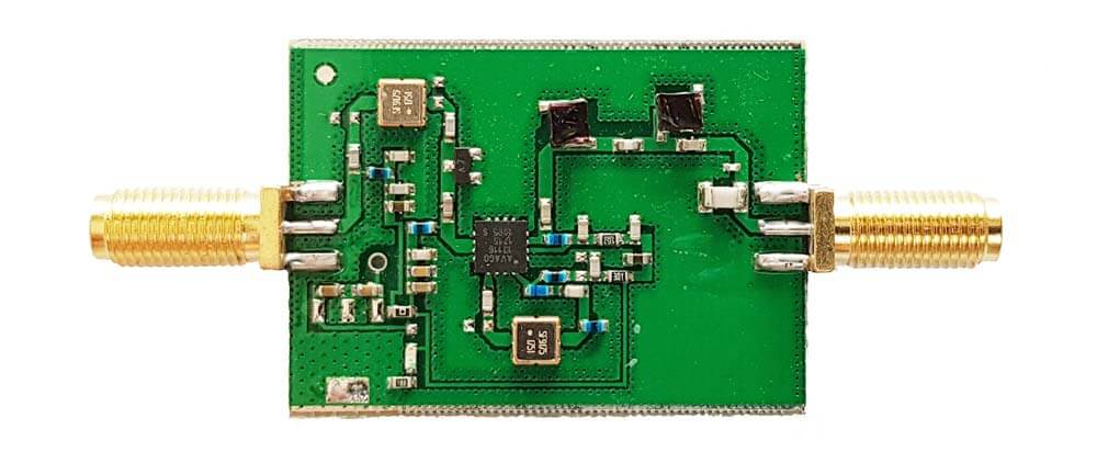
The gain of the RTL-SDR Blog ADS-B LNA is 27 dB's at 1090 MHz, and out of band signals are reduced by at least 60 - 80 dB's. Attenuation in the broadcast FM band and below 800 MHz is actually closer to over 100 dB's. In the LNA signal path there is first a low insertion loss high pass filter that reduces the strength of any broadcast FM, TV, pager or other similar signals that are usually extremely strong. Then in between the first and second stage of the LNA is a SAW filter tuned for 1090 MHz. A second SAW filter sits on the output of the LNA. The result is that strong out of band signals are significantly blocked, yet the LNA remains effective at 1090 MHz with a low ~1 dB noise figure.
The LNA is also protected against ESD damage with a gas discharge tube and low capacitance ESD diode. But please always remember that your antenna must also be properly grounded to prevent ESD damage.
Please note that this LNA requires bias tee power to work. Bias tee power is when the DC power comes through the coax cable. The RTL-SDR V3 has bias tee power built into it and this can be activated in software. See the V3 users guide for information on how to activate it. Alternatively if you don't own a dongle with bias tee built in, then an external bias tee can be used and those can be found fairly cheaply on eBay. Finally, if you are confident with soldering SMT components, then there are also pads and a 0 Ohm resistor slot on the PCB to install an LDO and power the LNA directly.
In addition please remember that this is a high gain LNA. It is expected to be used at the antenna side, with some 3+ db loss expected on the coax. However, if desired, it can still be used on the receiver side. If used on the receiver side or with a low loss run of coax, you will need to tune the RF gain on the RTL-SDR dongle. By default most software sets the RF gain to maximum. We recommend turning the RTL-SDR RF gain down to about 32 dB if connecting it directly to the dongle, otherwise the high input power may overload the dongle causing poor performance.
Specification Summary:
Frequency: 1090 MHz
Gain: 27 dB @ 1090 MHz
Return Loss: -16 dB @ 1090 MHz (SWR = 1.377)
Noise Figure: ~1 dB
Out of band attenuation: More than 60 dB
ESD Protection: Dual with GDT and ESD Diode
Power: 3.3 - 5V via bias tee only, 150 mA current draw
Enclosure: Aluminum enclosure
Connectors: Two SMA Female (Male to Male adapter included)
Dimensions:
46.5 x 32 x 15.6 mm (not including the SMA).
Including the SMA the length is 69.8 mm.
Testing
We tested our new LNA against another ADS-B LNA with filter built in that is sold by another company and the FlightAware Prostick+ dongle in an environment with strong out of band signals such as pagers, broadcast FM, DVB-T and GSM signals. The results showed that the RTL-SDR Blog ADS-B LNA gathered the most ADS-B packets. In the tests both LNA's were connected on the receiver side to be fair to the FA dongle. Improved performance could be achieved by moving the LNA to the antenna side.
Other ADS-B LNA vs RTL-SDR Blog ADS-B LNA Received MessagesFlightAware Prostick+ vs RTL-SDR Blog ADS-B LNA Received Messages
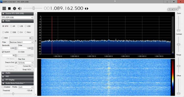
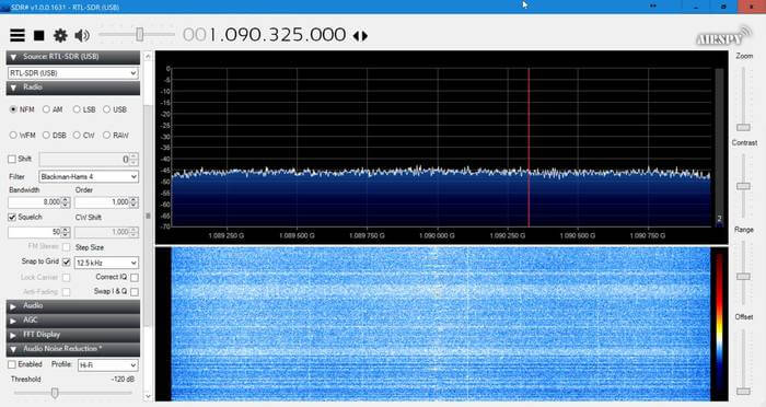
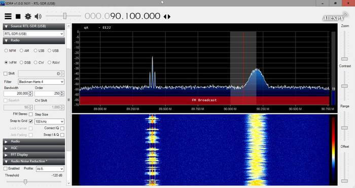
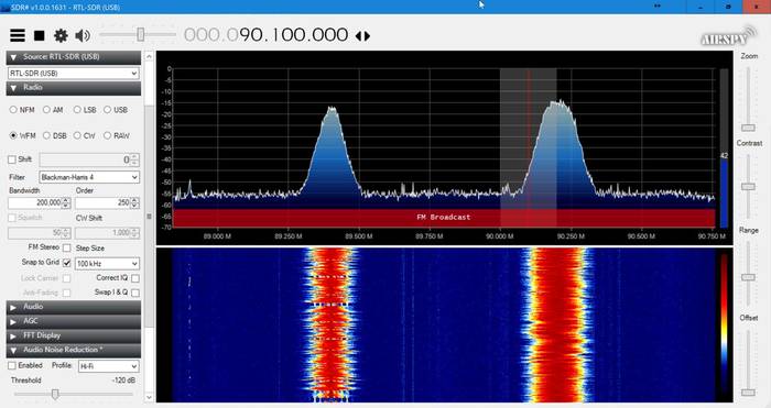
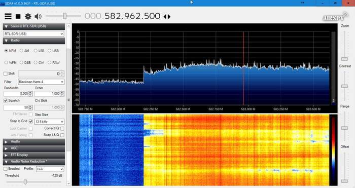
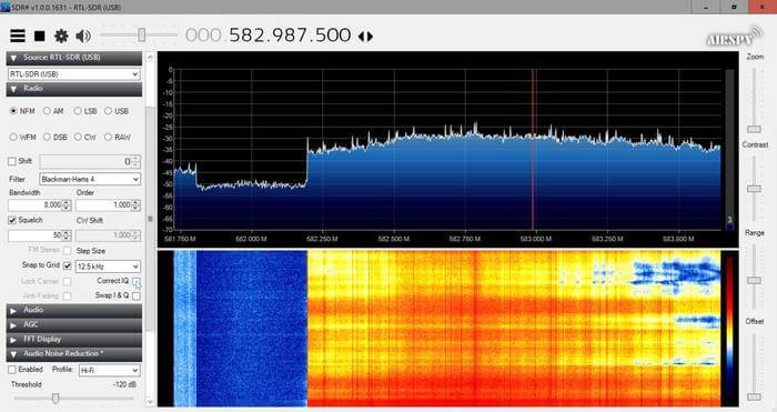
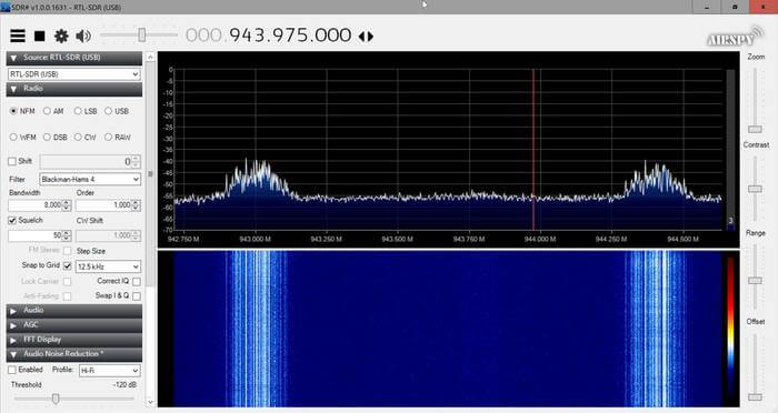
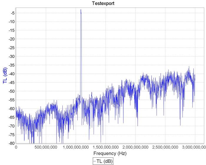
Checking in SDR# for out of band signals also showed that the RTL-SDR Blog ADS-B LNA significantly reduces those strong out of band signals, whereas the others have trouble blocking them out. Below we show the results as well as some measurements.
This RTL-SDR Blog ADS-B LNA can significantly improve ADS-B reception, especially if you are in an environment with strong out of band signals. Even if you are not, the low noise figure design will improve reception regardless.
In a post uploaded last month we noted that Outernet was selling off some of their old L-Band satellite antennas cheaply. Nils Schiffhauser (DK8OK) decided to take advantage of the sale and bought one. Now Nils has created a blog post that shows how he's been able able to decode 12 L-Band AERO channels simultaneously with the Outernet L-band antenna, an Airspy R2 and SDR-Console V3. AERO is the satellite based version of aircraft ACARS, and it's L-band signals contain short ground to air messages like weather reports and flight plans. Multiple channels are often in use at any one time.
To achieve this Nils uses the multi-channel tuning capabilities of SDR-Console V3, which allows him to open up 12-channels, each tuned to a different AERO frequency. He then opens up 12 instances of the AERO decoder known as JAERO, and then uses VB-Cable to pipe the audio from each channel into a JAERO instance. Nils writes that the key to making JAERO run with multiple instances is to install JAERO into different folders on your PC, and give each JAERO.exe a unique file name like JAERO_1.exe.
He collects all the data into a program called Display Launcher and Nils notes that the whole set up has been stable digesting 54,000 messages over the last 24 hours.
Cubesats are small shoebox sized satellites that are usually designed by universities or amateur radio organizations for basic space experiments or amateur radio communications. Typically they have an orbit lifespan of only 3-6 months.
Cubesats typically transmit signals at around 435 MHz, and they are powerful enough to be received with a simple home made antenna and an RTL-SDR. To help with this Thomas N1SPY has created a YouTube video where he shows exactly how to construct a cheap eggbeater antenna made out of a few pieces of copper wire and an SO-239 UHF connector. Later in the video he demonstrates some Cubesats being received with his antenna, an RTL-SDR and the SDR-Console V3 software.
2018: Thomas N1SPY chases mini satellites on a budget
Over on his blog author ByTechLab has posted about his 'mostly 3D printed' discone antenna. A discone is a type of wideband antenna, so it is commonly used with SDRs like the RTL-SDR that have huge frequency ranges. Building a discone can be difficult, but ByTechLab shows that with a 3D printer it is possible to print the aluminum rod mounts, which significantly reduces construction complexity. His post shows the exact directions, and the stl files are available over on Thingiverse.
Note that back in March we saw another 3D printed discone by mkarliner that used a full cone design with the cone being made out of aluminum tape. Discones based on aluminum rods should however be more weather resistant, and more able to withstand wind loads, so ByTechLab's design is more suitable for permanent outdoor mounting.
Over on Twitter and his github.io page, Pieter Noordhuis (@pnoordhuis) has shared details about his low cost RTL-SDR based GOES satellite receiving setup. GOES 15/16/17 are geosynchronous weather satellites that beam back high resolution weather images and data. In particular they send beautiful high resolution 'full disk' images which show one side of the entire earth. As the satellites are in geosynchronous orbit, they are quite a bit further away from the earth. So compared to the more easily receivable low earth orbit satellites such as the NOAA APT and Meteor M2 LRPT satellites, a dish antenna, good LNA and possibly a filter is required to receive them. However fortunately, as they are in a geosynchronous orbit, the satellite is in the same position in the sky all the time, so no tracking hardware is required.
In the past we've seen people receive these images with higher end SDRs like the Airspy and SDRplay. However, Pieter has shown that it is possible to receive these images on a budget. He uses an RTL-SDR, a 1.9 GHz grid dish antenna from L-Com, a Raspberry Pi 2, the NooElec 'SAWBird' LNA, and an additional SPF5189Z based LNA. The SAWBird is a yet to be released product from NooElec. It is similar to their 1.5 GHz Inmarsat LNA, but with a different SAW filter designed for 1.7 GHz GOES satellites. The total cost of all required parts should be less than US $200 (excluding any shipping costs).
Pieter also notes that he uses the stock 1.9 GHz feed on the L-com antenna, and that it appears to work fine for the 1.7 GHz GOES satellite frequency. With this dish he is able to receive all three GOES satellites at his location with the lowest being at 25 degrees elevation. If the elevation is lower at your location he mentions that a larger dish may be required. It may be possible to extend the 1.9 GHz L-Band dish for better reception with panels from a second cheaper 2.4 GHz grid dish, and this is what @scott23192 did in his setup.
For software Pieter uses the open source goestools software that Pieter himself developed. The software is capable of running on the Raspberry Pi 2 and demodulating and decoding the signal, and then fully assembling the decoded signal into files and images.
A Discone is a type of antenna that is designed to be resonant over a wide range of frequencies. Most antenna designs only really receive well on a few resonant frequencies, but a Discone is resonant over a much wider frequency range. This makes it a good partner for RTL-SDR and other SDR units as many SDRs tend to have wide tunable frequency ranges. With a wideband antenna like a Discone connected to an RTL-SDR one can scan over the almost entire tunable frequency range without needing to change antennas for each band. The drawbacks to a Discone however is that the antenna gain is not very high, and that it makes the SDR more susceptible to out of band interference. They also tend to be fairly expensive and difficult to build.
The Discone antenna is remarkable in that it is capable of receiving and transmitting over a wide range of frequencies with good matching. Because of this, it is a good match for SDR receivers such as the popular RTL-SDR sticks.
The only really tricking thing about making a discone is that the disc has to be balanced at the very top of the cone, which is mechanically awkward.
The two parts here allow the cone to be solidly clamped and provide an adequate base for the disk. There also two holes for bring the coax centre and braid out to the disc and cone. The base part has a socket at the bottom for 25mm (1 inch) plastic conduit for mounting
This antenna illustrated is designed for 400MHz and up, and as such transmits well on the 70cms amateur band, US and UK PMR channels and 23cms. It also receives aircraft ADS-B signals very well. I used .3mm plastic sheet for the cone and 2mm plastic for the disc, and then covered them with aluminium weatherproof tape. Be sure to check for continuity across the tape stripes.
The screenshot is of a calculator by VE3SQB which can be downloaded from http://www.ve3sqb.com/ if you want to make attenna's for other ranges.
A 3D Printed Discone
If you're interested in building wideband antenna there is also the planar disk antenna (pdf) which can be built out of pizza pans.
Over on the swling.com blog admin Thomas has been exploring various indoor antenna options for pairing with an HF capable software defined radio. He notes that unless you happen to live in isolation, you're highly likely to experience RFI problems with standard wire antennas. Instead he recommends looking into magnetic loop antennas which are significantly more resistant to urban electric field based RFI noise, and they can also be rotated to null out any other local noise sources. Thomas then goes on to highlight some of the best commercial magnetic loop options for sale. There is also some good advice in the comments section.
We note that magnetic loop antenna seem to work fairly well with the RTL-SDR in V3 in direct sampling mode, but you may need to filter out the broadcast AM band to avoid overload if the loop doesn't do this already.
An example small PK-Loop antenna for receiving shortwave with an SDR.
Thank you to Frank Sessink (PA0FSB) for submitting to us his document describing the K9AY loop antenna (pdf), which is the antenna that he successfully uses with his RTL-SDR for HF reception. The antenna combines magnetic (H) and electric (E) field reception in order to create a directive radiation pattern. Frank extends the idea by showing a method that can adjust the directivity electrically with some simple resistor switching.
The antenna that I use is for medium wave DX, specially to receive MW from USA here in Europe/The Netherlands. The antenna is a combination of a magnetic loop and a sense antenna for the E-field. The magnetic loop is directive, but has no front-rear ratio. The E-field antenna has omnidirectional sensitivity. The combination, in correct phase and amplitude, results in a front-rear ratio of more than 25 dB over the frequency range from 500 kHz to around 3 MHz. Higher frequency makes no sense, since skywave signals distort the ground wave directivity pattern.
A simple modification is used as directional antenna with remote control: two orthogonal loops that combine E and H-field in a simple way. I can make 8 selectable directions.
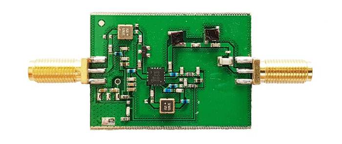
We're happy to announce the release of our new high performance low noise amplifier (LNA) for improving 1090 MHz ADS-B reception. The LNA uses a low noise figure high linearity two stage MGA-13116 amplifier chip and three stages of filtering to ensure that strong signals or interference will not overload either the amplifier or SDR dongle.
The LNA is currently only available from our Chinese warehouse, and costs US$24.95 including shipping. Please note that the price may increase slightly in the future, and that Amazon USA may not be stocked until March.
An LNA can help improve ADS-B reception by reducing the noise figure of the system and by helping to overcome losses in the coax cable and/or any other components such as switches and connector in the signal path. To get the best performance from an LNA, the LNA needs to be positioned close to the antenna, before the coax to the radio.
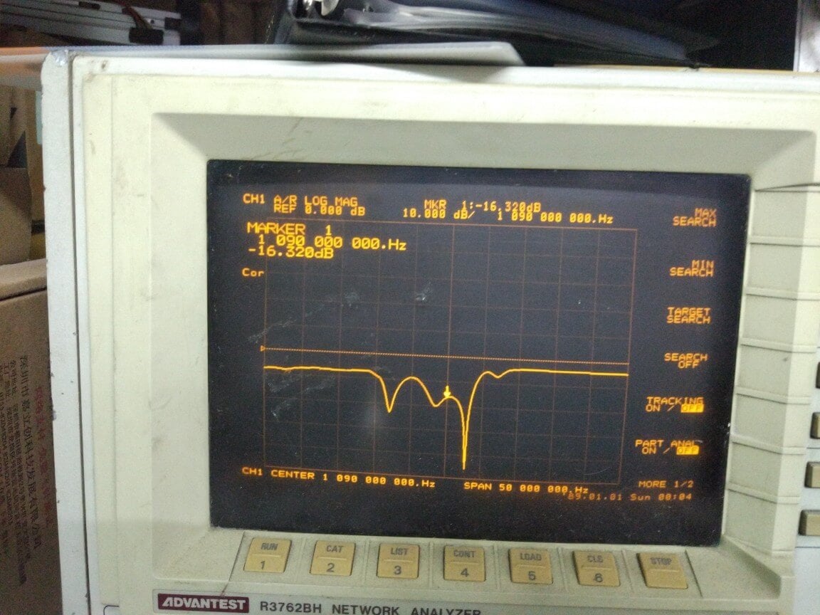
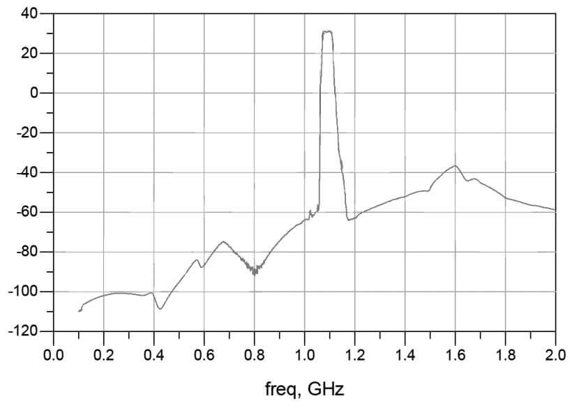
The gain of the RTL-SDR Blog ADS-B LNA is 27 dB's at 1090 MHz, and out of band signals are reduced by at least 60 - 80 dB's. Attenuation in the broadcast FM band and below 800 MHz is actually closer to over 100 dB's. In the LNA signal path there is first a low insertion loss high pass filter that reduces the strength of any broadcast FM, TV, pager or other similar signals that are usually extremely strong. Then in between the first and second stage of the LNA is a SAW filter tuned for 1090 MHz. A second SAW filter sits on the output of the LNA. The result is that strong out of band signals are significantly blocked, yet the LNA remains effective at 1090 MHz with a low ~1 dB noise figure.
The LNA is also protected against ESD damage with a gas discharge tube and low capacitance ESD diode. But please always remember that your antenna must also be properly grounded to prevent ESD damage.
Please note that this LNA requires bias tee power to work. Bias tee power is when the DC power comes through the coax cable. The RTL-SDR V3 has bias tee power built into it and this can be activated in software. See the V3 users guide for information on how to activate it. Alternatively if you don't own a dongle with bias tee built in, then an external bias tee can be used and those can be found fairly cheaply on eBay. Finally, if you are confident with soldering SMT components, then there are also pads and a 0 Ohm resistor slot on the PCB to install an LDO and power the LNA directly.
In addition please remember that this is a high gain LNA. It is expected to be used at the antenna side, with some 3+ db loss expected on the coax. However, if desired, it can still be used on the receiver side. If used on the receiver side or with a low loss run of coax, you will need to tune the RF gain on the RTL-SDR dongle. By default most software sets the RF gain to maximum. We recommend turning the RTL-SDR RF gain down to about 32 dB if connecting it directly to the dongle, otherwise the high input power may overload the dongle causing poor performance.
Specification Summary:
Frequency: 1090 MHz
Gain: 27 dB @ 1090 MHz
Return Loss: -16 dB @ 1090 MHz (SWR = 1.377)
Noise Figure: ~1 dB
Out of band attenuation: More than 60 dB
ESD Protection: Dual with GDT and ESD Diode
Power: 3.3 - 5V via bias tee only, 150 mA current draw
Enclosure: Aluminum enclosure
Connectors: Two SMA Female (Male to Male adapter included)
Dimensions:
46.5 x 32 x 15.6 mm (not including the SMA).
Including the SMA the length is 69.8 mm.
Testing
We tested our new LNA against another ADS-B LNA with filter built in that is sold by another company and the FlightAware Prostick+ dongle in an environment with strong out of band signals such as pagers, broadcast FM, DVB-T and GSM signals. The results showed that the RTL-SDR Blog ADS-B LNA gathered the most ADS-B packets. In the tests both LNA's were connected on the receiver side to be fair to the FA dongle. Improved performance could be achieved by moving the LNA to the antenna side.
Other ADS-B LNA vs RTL-SDR Blog ADS-B LNA Received MessagesFlightAware Prostick+ vs RTL-SDR Blog ADS-B LNA Received Messages
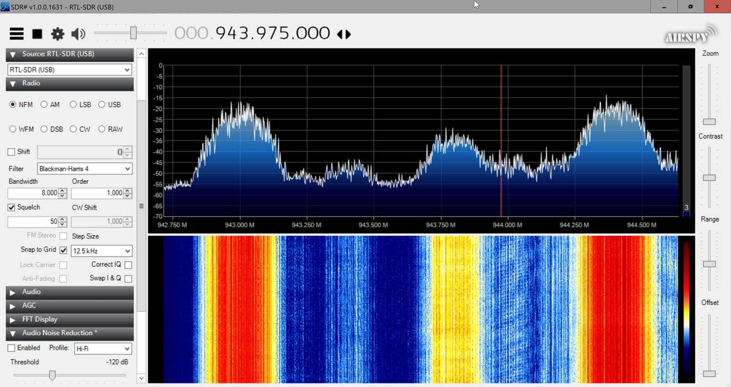
Checking in SDR# for out of band signals also showed that the RTL-SDR Blog ADS-B LNA significantly reduces those strong out of band signals, whereas the others have trouble blocking them out. Below we show the results as well as some measurements.
This RTL-SDR Blog ADS-B LNA can significantly improve ADS-B reception, especially if you are in an environment with strong out of band signals. Even if you are not, the low noise figure design will improve reception regardless.