Traditionally when we think about Software-Defined Radio we’re thinking about little USB adapters that unlock a world of radio in the palm of our hands. This is done by allowing us to directly sample the IQ data from the mixer within the SDR.
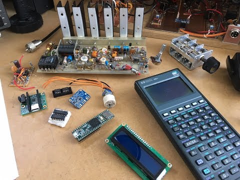
However, this isn’t the only way to experience Software-Defined Radio. Ham Radio operator [Charlie Morris] has uploaded a 10 part series on YouTube explaining how he implemented his own HF transceiver, including custom software. Some of the components such as the amplifier and filters are built completely from scratch, other components use a little DSP magic from a “Teensy” microcontroller.
Charlie actually samples the I and Q data in a similar way that today’s SDRs do and even implemented the transmit side of the radio so he can make contact with other radio operators around the world, and man… it sounds good!
You can find a complete playlist from Charlie with well-explained videos that go over his entire process from planning, schematics, layout and final operation. The channel appears to be quite active and will surely continue to pump out amazing content.
Homebrew SDR SSB Rig - Part 1 Design Ideas and Thoughts
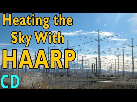
Over on YouTube Curious Droid has uploaded an interesting video that attempts to explain the purpose of the HAARP transmitter project. The High Frequency Active Auroral Research Program (HAARP) is an ionospheric research program based in Alaska. It consists of a high power transmitter and antenna array which is used to excite a portion of the atmosphere in order to study the ionosphere and investigate methods of affecting radio communications. Recently HAARP was also used in an art project called "Ghosts in the Air Glow" which saw HAARP used to transmit several audio art pieces.
HAARP has also been a popular target of conspiracy theorists who believe that the transmitter must have some sort of sinister purpose. Curious Droid's video explains the purpose and science behind HAARP elegantly, hopefully dispelling any conspiracy theories.
He also explains where some of the conspiracy theories may have originated from. The original idea that HAARP was based on was a patent claiming the ability of Ionospheric heating to disrupt communications, take down missiles & satellites, affect weather, scan the earth and even affect brains. However, a project with such abilities would require ridiculous levels of electrical power and land space for the antennas, making it very unrealistic.
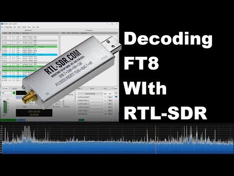
Over on YouTube user ModernHam has uploaded a useful tutorial showing how to use our RTL-SDR Blog V3 dongles for FT8 monitoring. The RTL-SDR Blog V3 has a built in direct sampling circuit which allows for reception of HF signals without the need for any upconverter. FT8 is an amateur radio weak signal digital communications mode which can be received all around the world even with low transmit power.
In his setup he uses SDR# and Virtual Audio Cable to pipe audio to the WSJT-X decoder. His video goes through all the steps and settings that need to be set and then shows a demo of some signals being received. ModernHam also has another video uploaded a few days earlier which is a more general introduction to FT8 decoding.
If you're interested we uploaded a tutorial last year that shows how to set up a Raspberry Pi 3 based FT8 decoding station with a V3 dongle.
Decoding FT8 with a RTL-SDR (Software defined Radio)
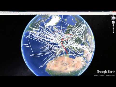
Over on YouTube user Shortwave Bavaria has uploaded a video that demonstrates HFDL reception. HFDL is short for High Frequency Data Link and is a signal used by aircraft to communicate short messages with ground stations over long distances. It is often used in place of VHF ACARS when flying over oceans.
In his video Shortwave Bavaria uses a 26.5m end fed wire, and a Cloud-IQ SDR. But we note that any HF capable SDR can be used to receive HFDL. SDR-Console V3 is used as the receiver, and MultiPSK Professional edition as the decoder. Many HFDL messages contain location data, so aircraft can be plotted on a map and he demonstrates this using Google Earth. In the video he notes how amazing it is that flights from across the globe can be received with his set up.
Amazing Decoding HFDL reception with SDR over central Europe
The Hermes-Lite is able to be very low cost (less than $300) because it is based on the AD9866 chip which is a mass produced RF front end (LNA + ADC & DAC) used in cable modems. Because it is a mass produced commodity, the chip only costs approx. US$35-$25 on Mouser depending on quantity. The chip has a 12-bit 80 MHz ADC and DAC, meaning that if used without any analog mixer front end (like in the Hermes-Lite) it can receive the entire spectrum between 0.1 to 38 MHz all at once.
The Hermes-Lite is also a lot more than just the RF chip, as it contains a set of switched RF filters and a 5W power amplifier for TX. It also interfaces with a PC via Ethernet and has a built in FPGA for DSP processing.
Recently Steve presented at the FOSSi Foundation Latch-Up conference on May 4-5, and a YouTube recording of his presentation is shown below.
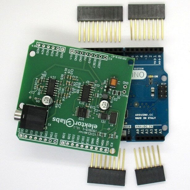
Elektor is a popular electronics magazine and hobbyist kit store. Recently they have published a book titled "SDR Hands-on Book" written by Burkhard Kainka. The book is intended as a companion to their Arduino SDR shield kit, which is a low cost module that allows you to turn an Arduino into a 150 kHz to 30 MHz capable SDR. It is based on the G8JCFSDR, which is an RF front end downconverter that allows a PC soundcard to be used as an SDR analog to digital converter.
Kainka's book goes over introductory topics such as shortwave reception, explains signal to noise ratio and interference, different types of antennas, software, digital modes, SDR measurements, receiving and finally WSPR and QRP transmission. If you're interested Jan Buiting also recently reviewed the book on the Elektor website.
Elektor are currently running a promotion and are selling the book + Arduino shield for a reduced price of €49.90.
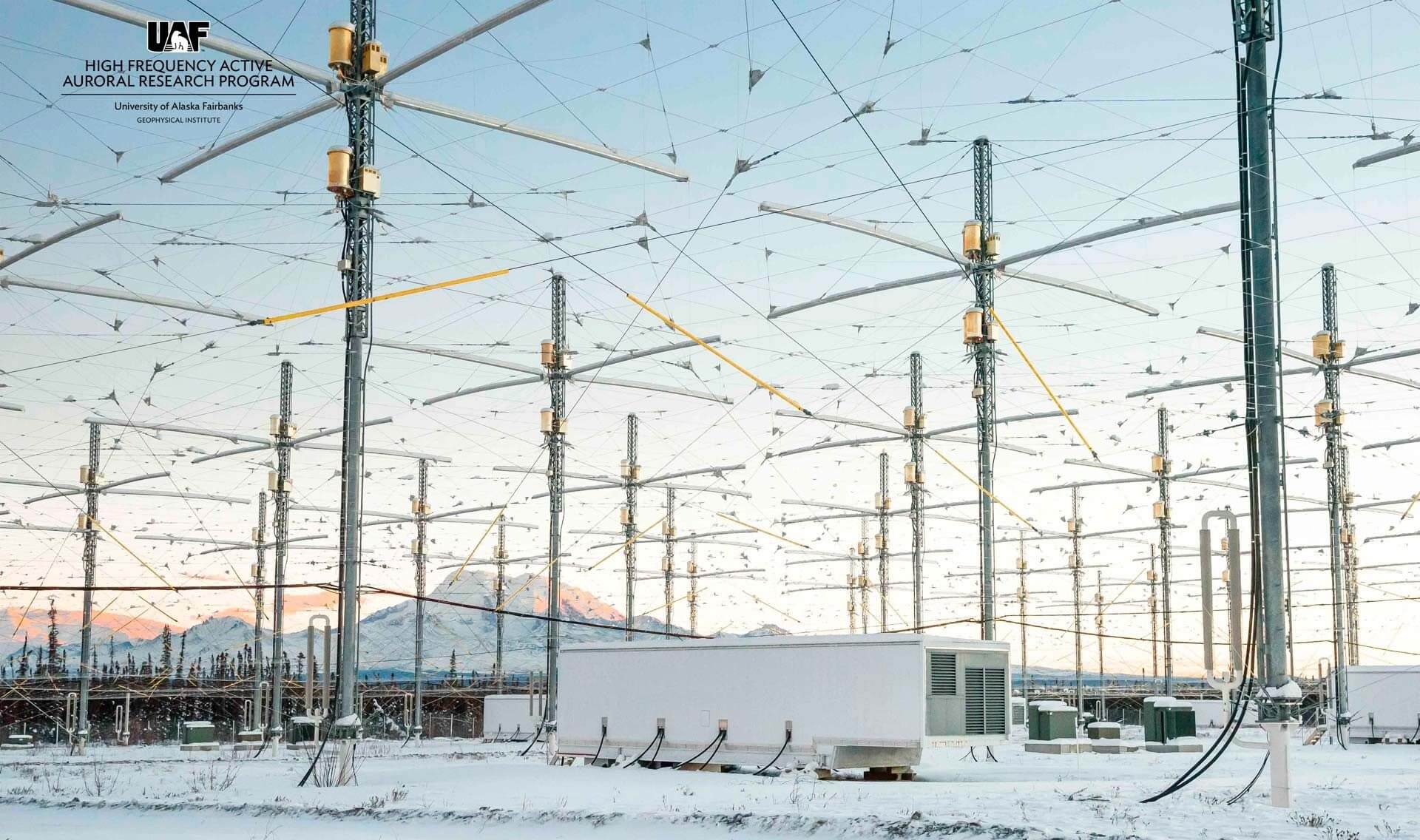
The famous HAARP (High Frequency Active Auroral Research Program) antenna array will be transmitting again from March 25 - March 28, 2019. HAARP is an antenna array which is used to perform experiments on the Earth's ionosphere and thermosphere by transmitting HF RF energy into it. With an HF capable receiver like the RTL-SDR V3 it is often possible to receive these transmissions from some distance away. As HAARP only rarely transmits, it is an interesting signal to catch when it is transmitting.
HAARP (High Frequency Active Auroral Research Program)
Ghosts in the Air Glow is an ionospheric transmission art project using the HAARP Ionospheric Research Instrument to play with the liminal boundaries of outer space.
Pairing air glow experiments in the ionosphere—false auroras creating soft, glowing spots in the sky—with SSTV images, audio and image signals articulated by artist Amanda Dawn Christie will be received and decoded via SDR (Software Defined Radio) equipment by amateur radio operators around the world, and streamed live online for audiences who do not have the equipment or expertise for reception.
“The facility, which was used by the military, has an air of mystery about it and has been the subject of many conspiracy theories over the years — that’s something I reflected upon when creating the piece.”
Ghosts in the Air Glow will consist of an hour-long transmission containing eight movements, each created for a specific frequency and intended to explore different concepts related to radio science and the HAARP site itself.
From Arctic wolves meeting the aurora to poetic texts written in Morse code and the NATO phonetic alphabet, the motifs covered by this transmission art work address issues related to military research, surveillance, political territories, ionospheric science, and conspiracy theories.
The first art transmission was sent earlier today, and if you missed it Amanda live streamed the signals being received on YouTube and the recording is available here. Future live streams will be available here. DK8OK has also posted about his reception on his blog.
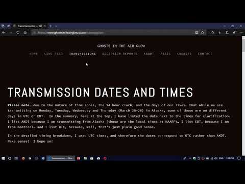
Further transmissions are scheduled every day until March 28, and the transmissions schedule is available here. Each transmission consists of several 'movements', which consist of differing antenna array arrangements, frequencies being used, and signals being transmitted. If the text formatting of the movements is a bit difficult to read, Reddit user
grink has formatted it into a nice table in his post. To follow the transmissions it would be also wise to follow Amanda on Twitter, where she is posting the most up to date transmission frequencies.
The idea for the project came about when Christie met Christopher Fallen, the chief scientist at HAARP, at a hackers conference earlier this year. Fallen, who is an amateur radio operator, was intrigued by Christie’s proposition to use the IRI to create site-specific transmission art.
He agreed to open the facility to her, and when she gained backing from the Canada Council for the Arts, Ghosts in the Air Glow officially became the first Canadian-funded project to take place at HAARP.
“Art and science are often seen as separate efforts but they actually share many of the same inspirations and techniques. I’m excited to see HAARP, a unique scientific instrument, used for a comparably unique artistic performance,” says Fallen.
“Amanda’s project will be a valuable contribution to the 50-year collection of scientific work in the field of ionosphere radio modification, and also to the brand new collection of artistic work using powerful high-frequency radio transmitters and the upper atmosphere — it’s art directed from the ground but created in space!”
Interdisciplinary artist Amanda Dawn Christie. Photo by Concordia University
If you prefer a video explanation of the project, YouTube user OfficialSWLchannel has prepared a video which is shown below.
HAARP tests and Ghost in the Air Glow from Amanda Dawn Christie
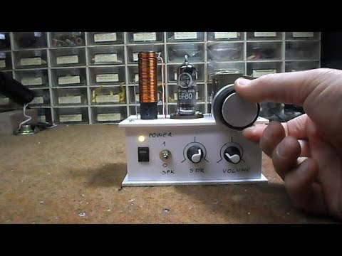
Vacuum tubes are not typically found in software defined radios, but this interesting mix of old and new technology by Mirko Pavelski uses one in it's front end. The way it works is that the analogue radio circuit receives a small range of spectrum, and then the tube acts as a mixer, converting that spectrum down into audio frequency range which can be heard by a computer sound card.
The sound card acts as the ADC, digitizing the signal, and then the "SDRadio" software performs the final filtering and demodulation of a narrowband signal in software. This is the same concept used by other HF sound card SDRs such as the Softrock, although those of course do not use tubes in their design. Mirko writes:
Simple to build receiver made according to the instructions of Burkhard Kainka : http://www.b-kainka.de/bastel100.htm. I made it with EF80 tube instead EL95 and it works great. It is powered by a 7.4V lithium-ion battery followed by a 7806 stabilizer, so we get 6v for tube heating and there are no problems with 50 Hz hum. Тhe resonant circuit is made of strong coil with 20 turns of 1.5 mm thick wire wound on a PVC tube with 18 mm diameter. At the cold end of the resonant circuit is an antenna coil with two turns. At the output of the radio, I connecт 2 transistor preamplifier and cheap amplifier module in D class. So we get battery powered tube АМ radio. Using the potentiometer we can select between AM or SDR mode of operation.
In SDR mode, we need to connect the output of the radio to "line in" in sound card of the computer. Then we use some of the free software for example "SDRadio" from Alberto I2PHD. Тhe receiver has very good frequency stability which drifts less than 1 Hz per minute. Тhis is important if we want to decode DRM signals. In good HF propagation conditions I receive BBC World service DRM radio (3995MHz) with 16dB SNR here in Ohrid (41.1231° N, 20.8016° E). This little radio, with a long wire antenna and good grounding, gives us a lot of fun.