Category: HF

RTL-SDR Front End Filter Demonstration

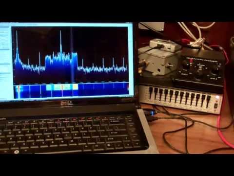
Over on YouTube user kugellagers has uploaded a video demonstrating the effect of some front end filters he constructed in order to reduce the effects of intermodulation from strong local AM and FM broadcast radio stations.

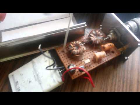
To attenuate strong broadcast FM signals, he used a very cheap FM trap from MCM Electronics. An FM trap (aka FM bandstop filter) is designed to attenuate signals in the FM band only. However, as a single FM trap was not strong enough for him, he took two FM traps out of their original casing and connected them together in a larger box for increased attenuation.

To attenuate strong broadcast AM signals he designed and created a home made 7th order LC elliptic high pass filter. With the filter in place he is able to receive a station at 2.5 MHz, but without it he shows that is unable to receive it clearly due to broadcast AM intermodulation.

RTL SDR Front End Filter Demonstration

Teensy SDR Updates and User Interface Demo

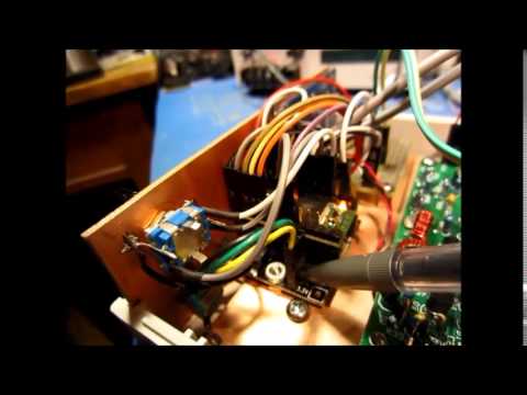
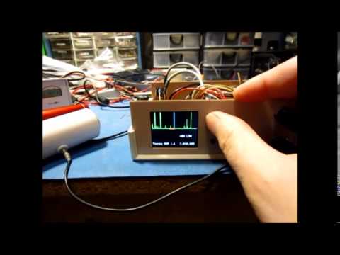
Last year in April we posted about the Teensy SDR, which is a SDR project that involves running a SoftRock SDR on a Teensy 3.1 Microcontroller. The Teensy is a tiny microcontroller board that uses a 32-bit ARM processor and the SoftRock SDR is a HF only software defined radio kit that is capable of RX and TX. Back then the Teensy SDR has no enclosure and the user interface hadn’t been finished.

In his latest YouTube videos, creator of the Teensy SDR rheslip20 (aka VE3MKC) shows his latest improvements to the project and in the second video shows off the user interface. In the future he hopes to implement TX capability too.


Teensy SDR User Interface Demo - Tuning around the bands

Low Pass Filter for RTL-SDR Direct Sampling Mode

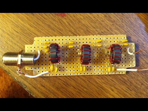
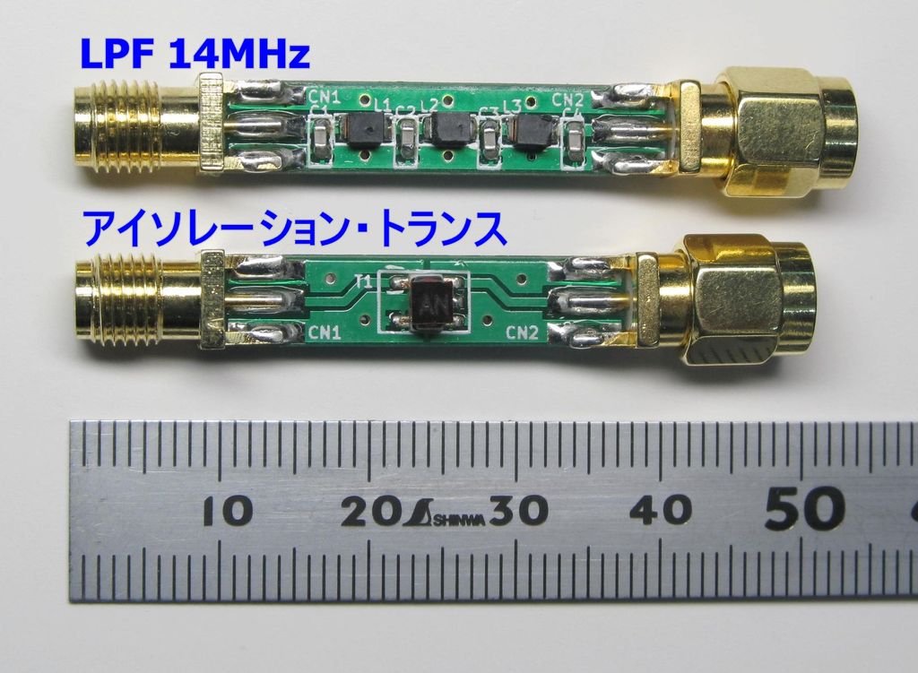
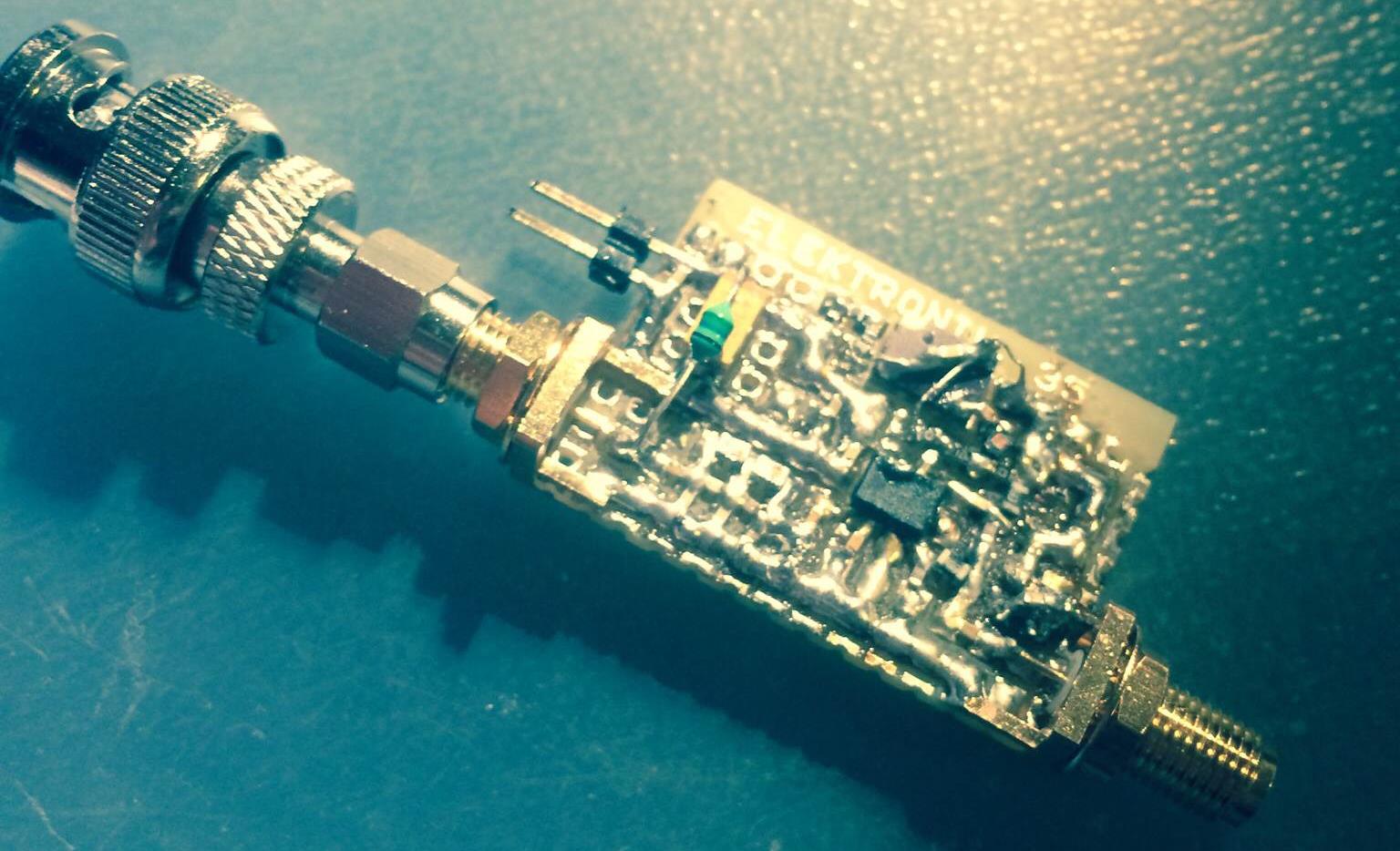
Over on his blog (in Japanese) Nobu has been working on prototyping a 14 MHz low pass filter (LPF) product for direct sampling modified RTL-SDR dongles (in Japanese, use Google Translate). Direct sampling mode is a hardware modification that allows the tuner chip in RTL-SDR dongles to be bypassed, allowing reception of signals between 0 – 14 MHz. However, after performing this mod there is no filtering and images from higher frequencies such as broadcast FM can be problematic. To fix these problems a low pass filter is required.

Another product Nobu is working on is an isolation transformer (aka Galvanic Isolator) which can be used together with an upconverter to help reduce noise generated from common ground sources such as the PC. The isolation transformer is inserted between an upconverter and antenna.

Low Pass Filter (Top), Isolation Transformer (Bottom)

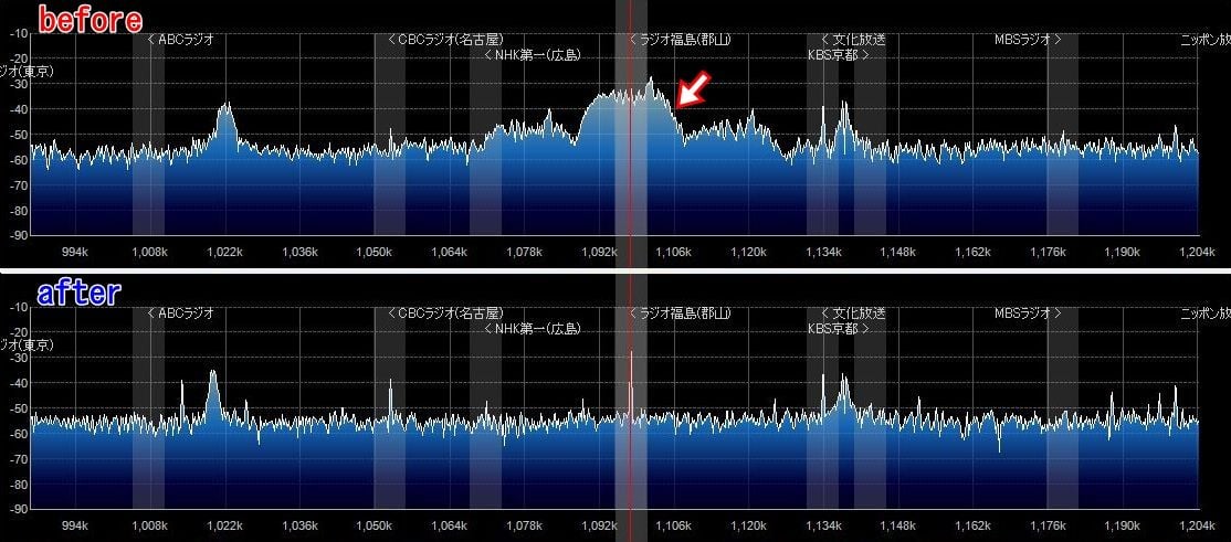
In the image below Nobu shows the effect of inserting the LPF . An interfering FM broadcast band signal is removed after inserting the LPF.

Effect of inserting the Low Pass Filter

The image below shows the effect of the isolation transformer showing a clear decrease in noise floor and increase in signal strength.

Effect of an Isolation Transformer when used with an Upconverter

Decoding Differential GPS Beacons with an RTL-SDR, Speclab and SDR#

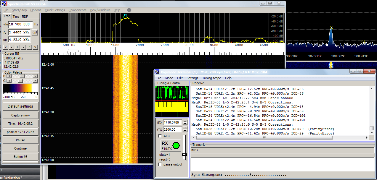
Over on his blog “RTL-SDR DX” dewdude has been exploring the reception and decoding of Differential GPS (DGPS) signals. DGPS signals are transmitted by government authorities in the long wave band at around 300 kHz. These beacons are used to dramatically improve the accuracy of GPS (Global Positioning System) devices from their default accuracy of about 15 m down to about 10 cm. Unlike GPS signals which originate from satellites, the DGPS signal is terrestrial based and is broadcast from multiple known fixed positions. The signal itself contains information about the difference between the DGPS stations received GPS position and it’s known exact position. These differences can be used to correct other GPS receivers that receive DGPS signal.

By using his RTL-SDR (with upconverter or HF modification) dewdude was able to receive the DGPS beacon in SDR#. Then by piping the output audio into SpectrumLab’s DGPS decoder he was able to decode the data contained within the DGPS signal. His post contains a tutorial showing how to set up SpectrumLab to decode DGPS. If you’re interested in hearing what a DGPS signal sounds like, dewdude has uploaded a sound sample at the bottom of another post of his.

Decoding Differential GPS (DGPS) signals in SpectrumLab

Building a simple upconverter with a NE612 IC

Upconverters are often used to extend the RTL-SDR dongles minimum receivable range down to the HF, MF and LF bands. They are available for purchase commercially, or you can build your own, which is what Tomasz of mightydevices.com has done.

By using a low cost mixer IC chip called the NE612 and some passive components Tomasz was able to build a low cost upconverter for his RTL-SDR. His upconverter uses a 100 MHz crystal oscillator that brings frequencies between 0-30 MHz up to a range of 100 – 130 MHz, which is in the receivable range of the RTL-SDR. The upconverter circuit was also designed to be able to provide inline power for a active (powered) Miniwhip antenna. Tomasz’s post explains the design choices and theory behind his circuit design.

An NE612 based upconverter
NE612 RTL SDR Upconverter

Using a Quantum Phaser to Null Out Interfering Signals

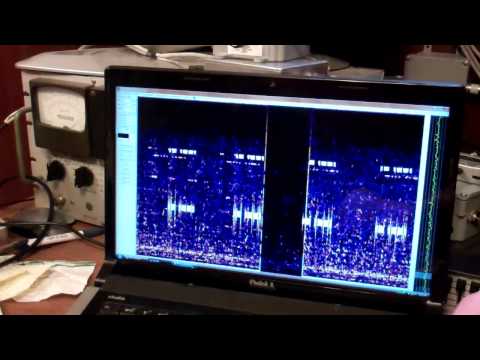
Over on YouTube user kugellagers has uploaded several videos showing how he used two vertical antennas together with an RTL-SDR and ham-it-up upconverter to demonstrate the effect of using a Quantum Phaser to null out strong interfering signals that can cause trouble when DXing.

A Quantum Phaser is a device that combines signals from two antennas in order to create a steerable null. Essentially this means that a strong nearby station coming from one direction that is overlapping a weak remote station coming from another direction can be heavily attenuated, allowing the weak station to come through.

In his videos kugellagers demonstrates the Quantum Phasers nulling effect with splatter from an AM station, an overlapping IBOC hash signal (AM HD Radio) and Non-Directional Beacons (NDBs).

Phasing Out Splatter From a 50 kW Local On Adjacent Channel

Phasing Out IBOC Hash From A Strong Local On Adjacent Channel

Phasing out LF/NDBs With Closely Spaced Vertical Antennas

Comparing the Ham-It-Up Upconverter with the SV1AFN Upconverter

Over on YouTube user Mile Kokotov has uploaded a video showing a comparison between the ham-it-up and SV1AFN upconverters. An upconverter allows reception of VLF to HF signals with SDR dongles such as the Airpsy and RTL-SDR.

Mile shows that both the ham-it-up and SV1AFN upconverters use the same core component, a double balanced mixer ADE-1. However, the ham-it-up comes with the option for a noise circuit to be populated. A noise circuit is useful if you want to measure the response of a filter or antenna for example. With the ham-it-up the noise source components are sold seperately and need to be carefully soldered on.

On the other hand the SV1AFN upconverter comes with a built in selectable LNA and better filtering circuitry. The SV1AFN upconverter also uses the ADE-1 in a slightly different design compared to the ham-it-up which allows for much improved performance at VLF frequencies.

In the results Mile uses his Airspy and shows that the SV1AFN upconverter is significantly better at receiving VLF frequencies, and also better at receiving a 28.205 MHz beacon. The results are summarized in the table captured from the video shown in the image below. In the second video Mile also compares the local oscillator drift of each upconverter.

Upconverter comparison results.
Upconverter comparison results screencap.
RF Upconverters Comparison: Ham it Up vs SV1AFN - part1

RTL-SDR Panadapter Using Hardware Radio Receiver IF Stages

Over on YouTube user Jay Moore has uploaded a video explaining how to connect an RTL-SDR dongle to the IF stage of a hardware radio in order to create a panadapter. In the video Jay briefly explains how a radio with an IF stage works and then shows how he tapped into his Sansui 2000 hardware radio’s IF stage directly from the circuit board. The IF stage then connects to a ham-it-up upconverter which connects to the RTL-SDR.

By connecting the IF stage of a hardware radio to the RTL-SDR it is possible to use the hardware radio as the receiver while using the RTL-SDR to still maintain the benefits of a spectrum display. Most purpose built hardware radios will have better reception than the RTL-SDR.

RTL-SDR on receiver IF stages