Category: News

New RTL-SDR Blog Units Now Available in Store: HF via Direct Sampling, Software Switchable Bias Tee, Less Noise/Spurs

A few months ago we brought out a poll asking readers of this blog what they might like to see in a revised RTL-SDR dongle. We’ve now taken some of those suggestions and implemented them into a brand new dongle. For now the price of the new dongle will remain the same as before at $24.95 USD for the dongle + antenna kit and $19.95 USD for the dongle only, but we may need to increase the price by $1 – $2 within the next few weeks due to our slightly increased manufacturing costs. Worldwide shipping remains free from the Chinese international warehouse, and US customers can order either from the Chinese international warehouse or from Amazon who will give you free shipping if you are a Prime member, or spend over $49. The Chinese warehouse is currently stocked and ready to ship, and Amazon is now stocked and should be ready to ship by the end of this week.

Please go to our store page at rtl-sdr.com/store for information on purchasing.
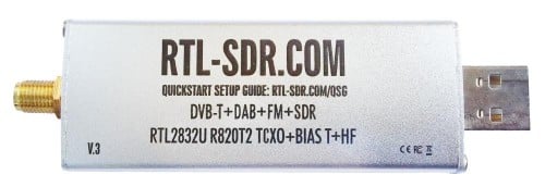
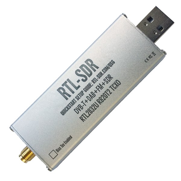
RTLSDR_Front

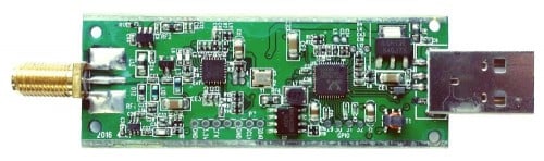
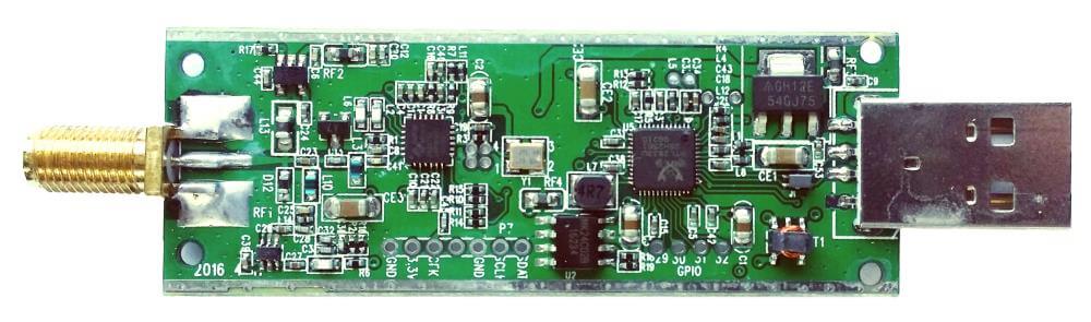
RTLSDR_PCB

Here is the short version of the biggest changes:

1) HF support via direct sampling. Connect an HF antenna directly to the SMA connector and tune from 500 kHz – 24 MHz with the direct sampling mod. (No hardware modding or soldering required)
2) Lower internal noise. Less spurs, lower noise floor etc.
3) Software switchable bias tee. No need to do any soldering to enable the bias tee. Can be turned on and off in software.

We call this version three of our RTL-SDR Blog dongles. The first was version zero and was simply the standard MCX dongles with better antennas. Next came version 1 with the bias tee and SMA connector, and version two introduced the metal case.

Here is the long list of improvements and changes, and why they were made:

1) Improved ESD protection on the radio front end. The BAV99 diode which is used on most dongles is not a true ESD rated diode. We have added a real ESD rated diode for better protection. The BAV99 remains in the circuit as a strong signal clipper, to prevent damage to the R820T2 from overly strong signals. Please remember that not even this will save your radio from a lightning strike, and any permanently outdoor mounted antenna system must have its own lightning protection.

2) Longer SMA connector. One or two customers had problems with the shorter SMA plugs which could not fit some of their antenna connectors. The longer shaft fixes this and also allows us to add a nut to fasten it to the aluminum body which provides a better low impedance connection (although this is not strictly needed as the PCB side ground tracks already provide a good connection).

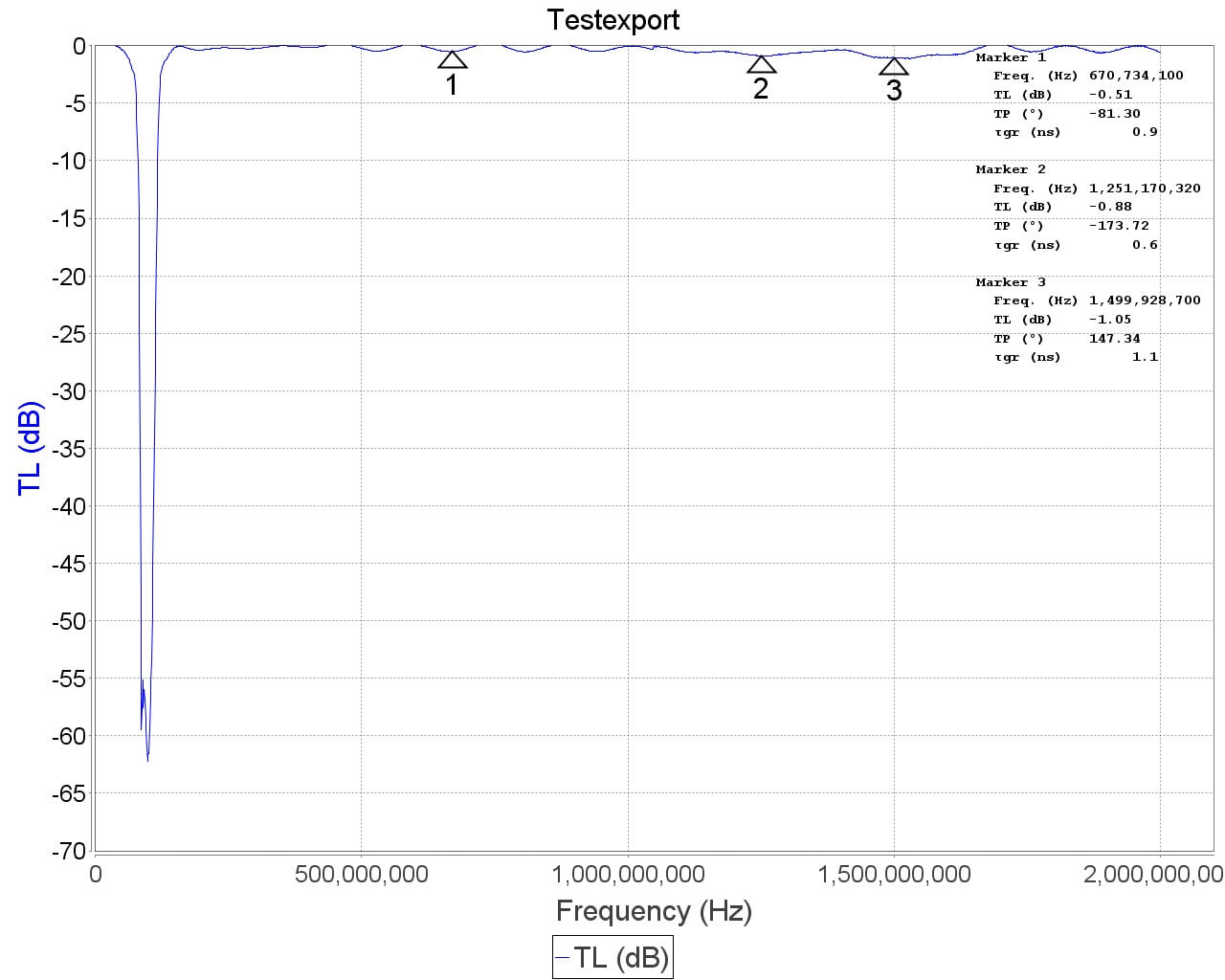
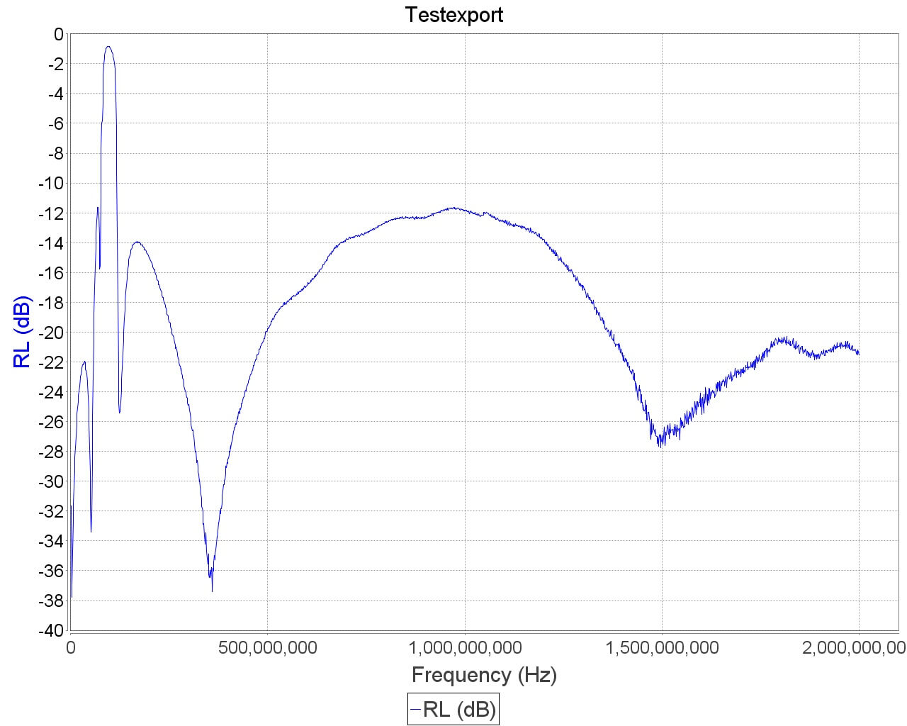
3) Improved front end circuit. The standard matching circuit on the RTL-SDR was designed for DVB-T use, and tends to attenuate signals above ~1 GHz. The new matching circuit has less attenuation above 1 GHz and similar performance below. We used very high quality, high SRF, high Q inductors in this circuit.

4) Added a software switchable 4.5v bias tee. In previous versions of our units the 4.5v bias tee needed to be activated manually, by soldering a bridge between two pads on the PCB. However we found that many customers who want to use the bias tee do not have the skills or tools to be able to perform this mod. The new unit makes use of a low noise LDO and one of the GPIO pins on the RTL2832U to activate the bias tee in software. This of course requires a modification to the drivers, but we will shortly upload a program called rtl_biast and batch files (available now) to turn the bias tee on and off in Windows and Linux.

This bias tee is great for powering a remote LNA (like Adams PSA5043+ based LNA4ALL) or something like the SpyVerter upconverter. We’ve tested it with both and found them to be running just fine. 

Warning: The bias tee LDO can be damaged if you short circuit it. Before turning on the bias tee, ensure the circuit to be powered is not shorted, or that the RTL-SDR is not connected to a DC shorted antenna!

5) Added several access pads on the PCB. Access pads for the unused GPIO pins, CLK in/out, 3.3V, GND and I2C pins have been added. The CLK input/output is disconnected by default (see change 6). Access pads for the I branch have also been added as some users and industrial customers are using these in special projects. These pads are only for advanced users who need them for special projects. Take care as these pins are not ESD protected.

6) Added a clock selector jumper. By soldering in a 4 pin 1.27mm pitch jumper header and removing the default 0 Ohm resistor, one can now easily select between the onboard clock, an external clock, or having the on board clock be the output for another dongle. This is for advanced users only who want to experiment with things like passive radar, and coherent receivers.

7) Reduced noise with a modified PCB design. This significantly reduces spurs and noise pickup due much lower impedance grounding and blocking of interference. Also added a USB common mode choke to reduce USB noise, several ferrite chokes on the PCB, and a lower noise LDO. A larger ground plane also improves on heat dissipation. 

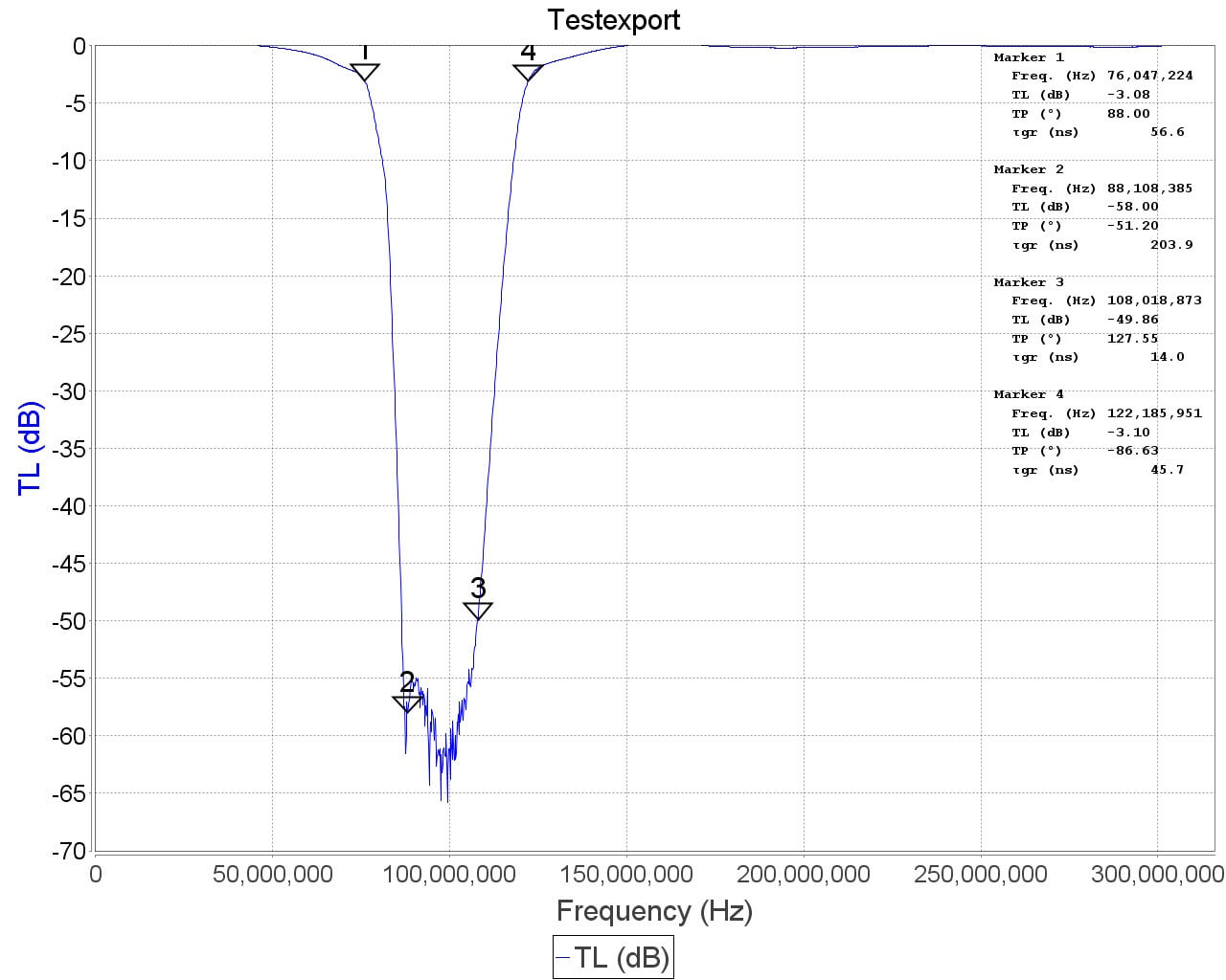
8) Added an experimental HF direct sampling circuit, which is diplexed out from the SMA connector. This has little to no effect on VHF/UHF operation, but allows us to make use of the Q branch on the RTL2832U chip for direct sampling, which allows us to receive from about 500 kHz to about 24 MHz. (Below 500 kHz is unavailable due to attenuation from the bias tee circuit). We used a ~10dB 50 Ohm preamp as a buffer and to overcome losses in the transformer and filter. We also added a strong 24 MHz low pass filter, and added an impedance matching transformer coil to ensure good direct sampling performance.

Of course direct sampling can never be as good as using an upconverter. It can overload easily if you have strong signals since there is no gain control. And you will see aliasing of signals above 14.4 MHz due to Nyquist. But this should at least give the majority of users a decent taste of what’s on HF. If you then find HF interesting, then you can consider upgrading to an upconverter like the SpyVerter (and the SpyVerter is of course compatible with our bias tee for easy operation).

We’re still classing this mode as experimental (and will be interested to hear any feedback on results), but we have had good results in our testing of this mode when receiving signals that are not too strong, getting sensitivity as good as an upconverter. We found that very good reception was obtainable with a long wire antenna and 9:1 unun combination.

9) Antenna bases now come with a stronger magnet and a conductive copper sticker on the bottom. The stronger magnet adds very good stability when using our large 1.5m antenna and the copper sticker ensures that good electrical contact can be made between the base and whatever piece of metal you use underneath as the ground plane. This significantly improves the antenna’s performance as a quarter wave ground plane.
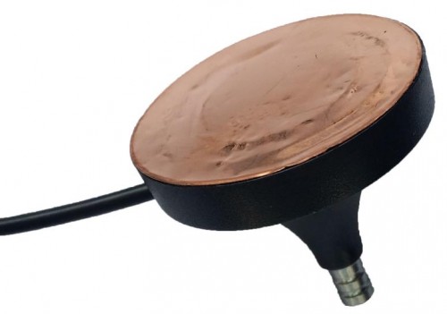
Ant_base_copper

10) Added corner mounting holes for those who want to stack PCBs. Some customers have been building devices that require multiple RTL-SDR dongles, and these standoff holes should aid in stacking.

As from the previous innovations the units still come with:

1) SMA connector – The most common connector in the radio world. Easy to adapt to other connectors and low loss over a wide range of frequencies.
2) Thermal pad – A thin thermal pad allows heat to transfer from the PCB to the metal case easily. The metal case then cools off to the surrounding air. This helps to solve L-band insensitivity problems.
3) Metal case – Helps block out interference and provides cooling.

We now have a V3 users guide available which explains how to use the new features such as the bias tee, HF mode and CLK jumpers.

What’s coming next?

We think that our unit is now pretty much at the peak of how good a cheap R820T2 RTL-SDR can be, so apart from minor tweaks this is likely to be our last major revision of this model of the RTL-SDR. In a 1-2 months we hope to bring out a FM bandstop filter with metal enclosure and SMA plugs with a target cost of $14.95 shipped. Further into the future we also hope to bring out supporting products like a wideband bias tee powered LNA and wideband antennas. These supporting products will of course be compatible with other SDR’s like the Airspy or SDRplay, or other RTL-SDR dongles.
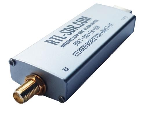
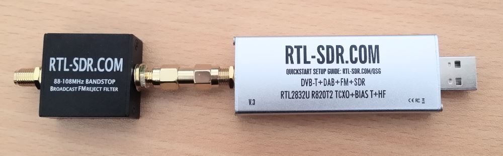
RTLSDR_Profile

RTL-SDR Blog SDR Unit Sale!

As many of you know we have been working on releasing a new revision of our RTL-SDR Blog SDR units for the last few months. We are a few weeks away from being able to release news about this new unit and begin sales.  At the moment we are still confirming the features and testing the prototypes so cannot release any news, but if you want a hint at what features might be coming you can take a look at our previous poll asking RTL-SDR users what they wanted in a low cost SDR. The new units may include some of these features/improvements.

For now we are selling off our current batch at reduced prices. The dongle only package is reduced from $19.95 to $17.95, and while the dongle + antenna kit is sold out in our international store, we have reduced its price from $24.95 down to $23.95 on our Amazon USA store.

You can purchase our units from our store at www.rtl-sdr.com/store.

These prices will only last until this batch of stock runs out, and there are only a few hundred units remaining. This special offer also combines with our 5% off deal if you buy more than two items from our store.

main_dongleonly_site2

Big Airspy Sale for US Customers: $149 Airspy R2, $99 Airspy Mini, $39 Spyverter

To celebrate the fourth of July, the US distributor of Airspy is throwing a sale. The prices are the lowest we’ve ever seen for any Airspy product before. Currently the sale price for an Airspy R2 is $149 (vs $199), $99 for Airspy Mini (vs $114) and $39 for the Spyverter. Unfortunately the sale only appears to be occurring with the USA distributor, and is not available for international customers.

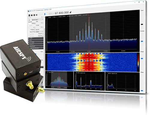
If you’re interested in these products see our previous review on the Airspy R2 vs HackRF vs SDRplay, review of the Airspy Mini, and our review of the SpyVerter. In short the consensus from our reviews is that the Airspy is an excellent product. The Spyverter is also the best upconverter we’ve tried, and is an excellent choice for an upconverter for any other non Airspy SDR, such as an RTL-SDR. And at this price it is even cheaper than most of the alternative options like the ham-it-up.

airspy_logo

An RTL-SDR to RTL-SDR QSO with RTL-TRX: Transmit RTTY with the RTL-SDR

Back in 2014 oh2ftg discovered that the RTL-SDR could actually be used to transmit data by modulating leakage from its internal local oscillator. Now it seems that tejeez and oh2ftg have released a new program that makes transmitting with the RTL-SDR easy. The program is called rtl-trx. It runs on Linux and allows you to to transmit RTTY or a simple beacon with the RTL-SDR. The software is available on GitHub at https://github.com/tejeez/rtl-trx. About how it works, the readme says:

Local oscillator leakage from an RTL-SDR dongle can be used as a very low power FSK transmitter. This program transmits RTTY and also makes it easy to use the same dongle to receive RTTY in between transmissions. The goal is to make it possible to have a two-way QSO between two dongles.

Over on YouTube oh2ftg has also uploaded a video that demonstrates the software in action by doing a 1270 MHz RTTY QSO between two modified RTL-SDR dongles. He uses fldigi to decode the RTTY signal and the signal is sent with the following settings: 425 Carrier shift, 45.45 Baud rate, 5 Bits per character, none Parity, 2 Stop bits. 
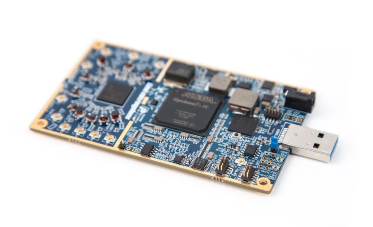
This previous post shows the hardware modification that can be done to improve the output power. Again, as with the Raspberry Pi transmitters, the output power is very low and probably won’t cause any trouble, but still please do take care if you intend on actually transmitting anything as the output spectrum is probably not very clean.

RTL2RTL QSO! on 1270MHz

LimeSDR CrowdFunding Closing in Four Days: 80% Funded

The LimeSDR is a new transmit capable software defined radio with a 100 kHz – 3.8 GHz frequency range, 12-bit ADC and 61.44 MHz bandwidth which is currently seeking crowdfunding. At the time of this post there is about four days left to reach the $500k goal, and it is only 80% funded. To try and reach their funding goal they have released another batch of discounted units which cost only $249 USD. After the crowd funding campaign the price will rise to $289/$299 USD. If the LimeSDR is not funded in time, they write that the project will unfortunately be put on hold and it’s future may be uncertain. We believe that this product is shaping up to be a very good TX/RX capable SDR, like the HackRF and bladeRF, but much better overall and for the same or even lower price.

Recently they also released some new updates that show off some LimeSDR features. In a post previously featured on our blog beta tester Alexandru showed how he was able to get the LimeSDR to transmit DVB-S2 HDTV. In later updates they showed how the LimeSDR can be used to:

The LimeSDR Board
The LimeSDR Board

Slovenian University Student & Security Researcher Almost Jailed for Researching TETRA with an RTL-SDR

Dejan Ornig, a 26 year old student at the University of Maribor’s Faculty of Criminal Justice and Security was recently almost jailed for finding a security flaw in Police TETRA communications in his home country of Slovenia. Back in 2013 his University Computer Science class of 25 was assigned a task to research security vulnerabilities in TETRA. TETRA is a RF digital communications protocol often used by authorities due to its ability to be secured via encryption. During his research he used an RTL-SDR and the open source Osmocom TETRA decoder, and discovered a flaw in the Slovenian Police’s TETRA configuration which meant that encrypted communications were often being broadcast in the clear. Translated, Ornig said:

For $20 I bought a DVB-T receiver (RTL-SDR), on the Internet, I have found also freely available and open-source software OsmoCOM. Free access solution for decoding the signal Tetra eighth-tetra is already prepared in advance programming framework based on the platform GNU.

He goes on to say (translated):

I was even more surprised when I found that most users do not have authentication turned on the radio terminal, even though the Ministry of the Interior in the documents and tenders repeatedly wrote to all the radio terminals to access networks using authentication.

Shortly after discovering the flaw, Dejan privately contacted the authorities with his findings. But after two years of repeatedly contacting them and waiting for a fix, Dejan decided to take his story to a local news agency in February 2015. At this point the Slovenian Police became interested in Dejan, and instead of fixing the problem, decided to conduct a search on his house, seizing his computer and RTL-SDR. After the search the Police made life harder for Ornig by trying to lump on other problems. During the search they found a “counterfeit police badge” in his house and apparently accused him of impersonating a police officer, and after a search of his PC they also decided to charge him after finding out that he covertly recorded his ex-employer calling him an “idiot”.

Ornig has now been given a 15 month suspended jail sentence for attempting to “hack” the TETRA network. Fortunately the suspended part means that in order to not go to jail Ornig simply must not repeat his crime again within 3 years. While SDR’s and radios are not illegal in most countries this is a reminder to professional and amateur security researchers to check that what you are doing is legal in your country. Even if it is for the overall good, Police often do not have the technical competence to understand security researchers and may react illogically to findings. The good news about Ornig’s story is that apart from the suspended jail sentence the authorities appear to have now worked with him to fix the problems.

TETRA Decoding
TETRA Decoding

Story Sources:
[http://www.ibtimes.co.uk/researcher-jailed-finding-security-flaws-police-communications-1561600]
[http://siol.net/novice/slovenija/kako-za-20-evrov-prisluskovati-slovenskim-varnostnim-organom-video-44923]
[https://podcrto.si/odziv-na-trditve-policije-glede-varnosti-komunikacijskega-sistema-tetra]

Testing a Prototype of the Outernet L-Band Downconverter

Outernet are a startup company that hope to revolutionize the way people in regions with no, poor or censored internet connectivity receive information. Their service is downlink only, and runs on C and L-band satellite signals, beaming up to date news as well as other information like books, educational videos and files daily. To receive it you will need one of their official or homemade versions of the Lighthouse or Lantern receivers (the latter of which is still to be released), or an RTL-SDR or similar SDR. Recently they began test broadcasts of their new 5 kHz 1539.8725 MHz L-band signal on Inmarsat I4F3 located at 98W (covers the Americas), and they hope to begin broadcasts in more regions soon too.

The typical RTL-SDR is known to often have poor or failing performance above 1.5 GHz (though this can be fixed to some extent), so Outernet have been working on an L-band downconverter. A downconverter works by receiving signals, and shifting them down to a lower frequency. This is advantageous because the RTL-SDR is more sensitive and does not fail at lower frequencies, and if used close to the antenna, the lower frequency allows longer runs of cheap coax cable to be used without significant signal loss.

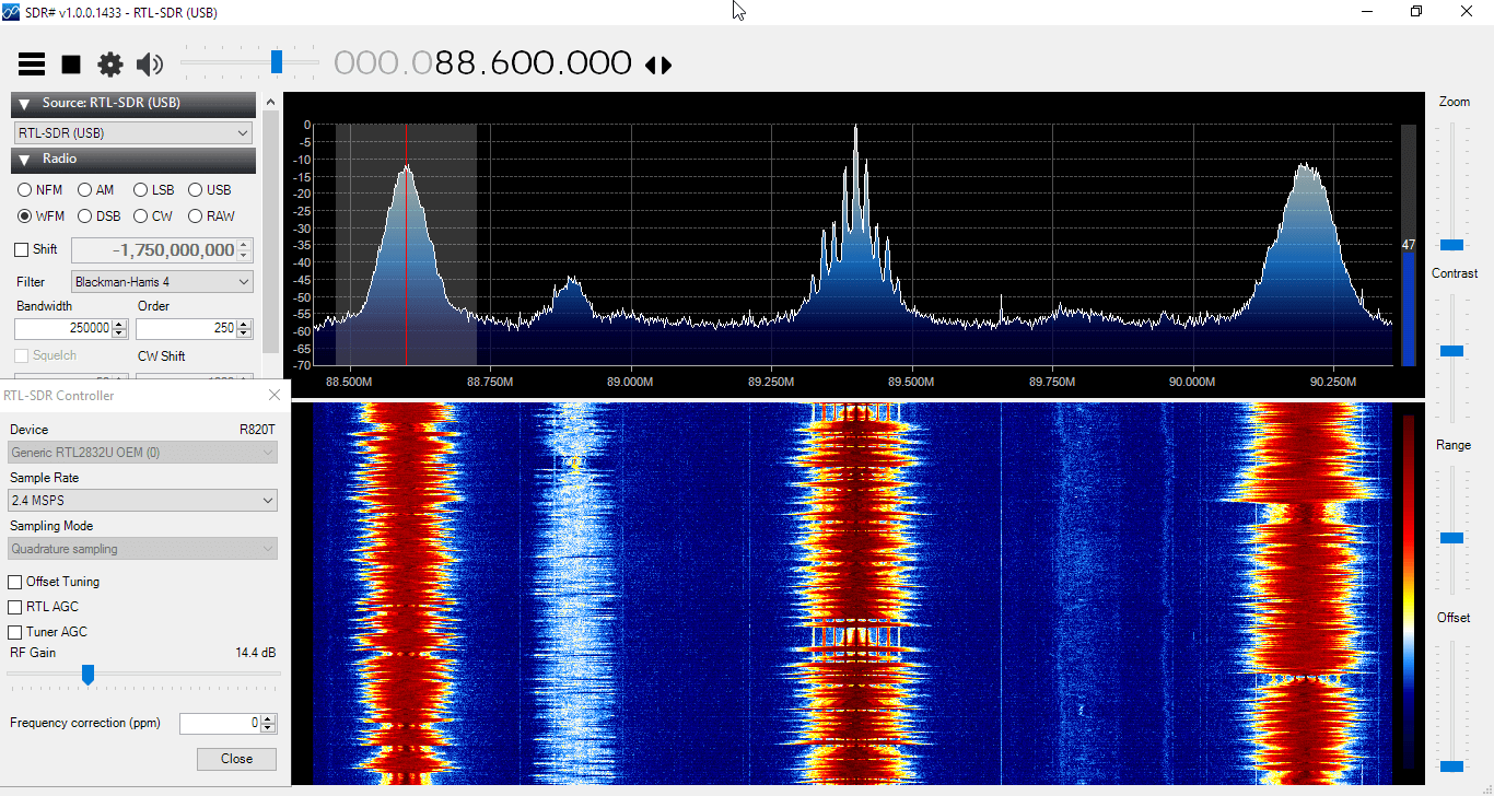
Earlier this week we received in the mail a prototype of their downconverter. The downconverter uses a 1.750 GHz LO signal, so any signal input into it will be subtracted from this frequency. For example the STD-C frequency of 1.541450 GHz will be reduced to 1750 MHz – 1541.450 MHz = 208.55 MHz. This also means that the spectrum will appear reversed, but this can be corrected by selecting “Swap I & Q” in SDR#. The downconverter also amplifies the signal with an LNA, and has a filter to remove interfering out of band signals.

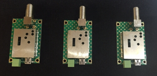
The Outernet downconverter circuit board.
The prototype Outernet downconverter circuit board.
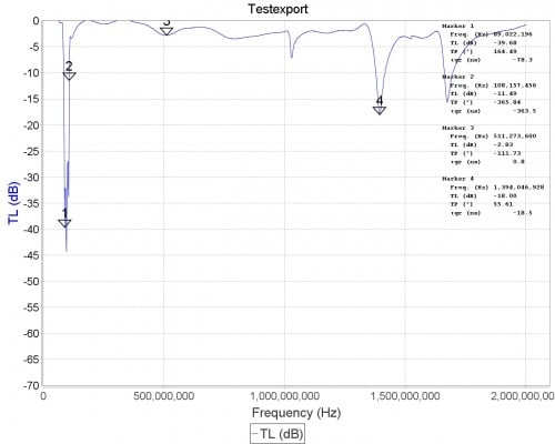
Specsheet for the downconverter.

We tested the downconverter using their patch antenna which they had sent to us at an earlier date (the patch antenna is used and shown in this Inmarsat STD-C reception tutorial). Our testing found that overall the downconverter works extremely well, giving us much better signal levels. Previously, we had used the patch + LNA4ALL and were able to get reception good enough to decode STD-C and AERO signals, but with the requirement that the patch be carefully pointed at the satellite for maximum signal. With the downconverter the signals come in much stronger, and accurate pointing of the patch is no longer required to get a signal strong enough to decode STD-C or AERO.

The downconverter can be powered by a bias tee connection, and this works well with our bias tee enabled RTL-SDR dongles. We also tested with the bias tee on the Airspy R2 and Mini and had no problems. It can also be powered with a direct 5V connection to a header, and they note that the header will be replaced by a USB connector in the production version.
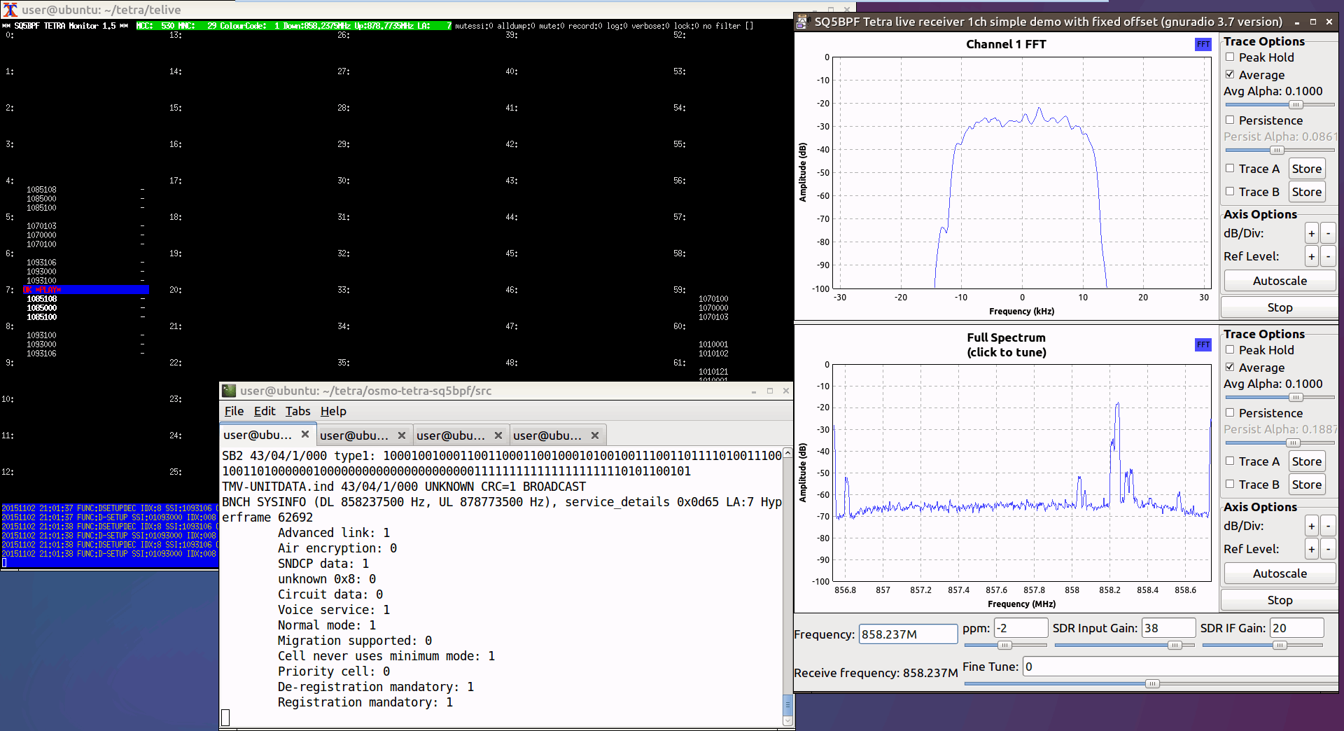
The release date and exact price that these will be sold at is not confirmed, but we believe that it will be priced similarly to upconverters at around $50 USD or less. A good low cost downconverter should help RTL-SDR and other SDR users receive not only the Outernet signal better, but also other satellite signals such as STD-C and AERO. Although the input is filtered and the RF frequency is specified at 1525 to 1559 MHz, we had no trouble receiving signals up to GPS frequencies of 1575 MHz, and even up to Iridium signals at 1.626 GHz, though reception was much weaker up that high.

Below are some screenshots of reception. Here we used the Outernet patch antenna sitting in a windowsill with the downconverter directly after the antenna, and then 10 meters of RG6 coax cable to the PC and bias tee enabled RTL-SDR. We found that with the downconverted ~200 MHz signal the loss in the RG6 coax was negligible. Better reception could be obtained by putting the patch outdoors. In some screenshots we used Vasilli’s R820T driver with the decimation feature, which allows you to zoom into narrowband signals much more clearly.

Some AERO Signals Zoomed in with the Decimation feature in SDR#.
Some AERO Signals Zoomed in with the Decimation feature in SDR#. Received with the Outernet downconverter and patch antenna.
Some AERO and other Signals Zoomed in with the Decimation feature in SDR#.
Some AERO and other Signals Zoomed in with the Decimation feature in SDR#. Received with the Outernet downconverter and patch antenna.
Signals zoomed out.
Signals zoomed out. Received with the Outernet downconverter and patch antenna.

Multi-RTL: A GNU Radio Block for Combining and Time Synchronizing Multiple RTL-SDR Dongles

The RTL-SDR has a maximum available stable bandwidth of about 2.4 MHz. Many people have had the idea to combine multiple RTL-SDR dongles together to implement a wider band or multi channel RX device, but very few successful implementations have been seen. The biggest challenge is time synchronization between the multiple RTL-SDR units. Even if a common clock is used, there is no guarantee that the samples streams are synchronized, which can cause problems for the decoding of many signals. The most successful implementations so far have used a common clock, and an external synchronization signal from a generator in addition to other hardware like switches.

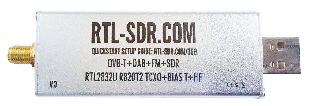
However, now Piotr Krysik has come up with a very good and simpler solution for the synchronization of RTL-SDR dongles. Piotr wanted to be able to capture both GSM uplink and downlink channels at the same time. As these channels are not close to each other in the frequency spectrum, he needed two synchronized RTL-SDR dongles to be able to monitor the two channels at once. In order to achieve synchronization he created a GNU Radio block called Multi-RTL, and connected two RTL-SDR dongles to a common clock source.
In his Multi-RTL block he implemented a method of a discovery he made that allows a way to time synchronize the dongles by using a signal that is already being broadcast over the air. He writes that his method is the following:

  • tuning the RTL-SDR dongles to the same frequency where some transmission is present,
  • recording a short signals with all of the dongles,
  • computing cross-correlation of the signals (i.e. with respect to a one selected channel),
  • finding position of maximums of cross-correlations in order to estimate relative delays of the channels,
  • correcting the delays so the channels are time-synchronized,
  • switching the dongles to their target frequencies,
  • changing other parameters of the channels (like gains) to target values.

With his Multi-RTL GNU Radio block Piotr was able to successfully monitor a GSM uplink and downlink channel pair that were spaced 45 MHz apart. Whilst monitoring the signals he sent an SMS to his phone, and then using his recovered encryption key was able to use gr-gsm to decode his message.

The successful implementation of this tool opens the door for many more RTL-SDR based projects, such as the reception of GSM uplink and downlink channels simultaneously, reception of frequency hopping signals, passive radar, and the receiving and decoding of signals with a bandwidth wider than 2.4 MHz.

Two dongles with a common clock.
Synchronizing two dongles by using an external signal.