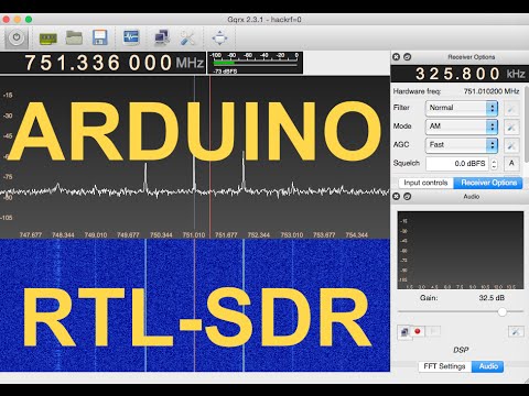
Over on YouTube user Samy Kamkar has uploaded a video showing how he was able to use an RTL-SDR to copy his friends wireless doorbell signal and prank him by replaying it using an Arduino and 433 MHz transmitter. His video goes through the entire reverse engineering process he used from recording the wireless doorbell signal with the RTL-SDR, to analyzing and understanding the signal and finally to programming the Arduino with the code to replicate the doorbell signal. If you don’t like video explanations, Samy has also done a write up of the same material on his website.
Digital Ding Dong Ditch Prank - hacking wireless doorbells w/Arduino and RTL-SDR
In our last postAdam Alicajic showed us on YouTube how to determine the frequency response of an RF filter using just a wideband noise source an LNA and an RTL-SDR dongle.
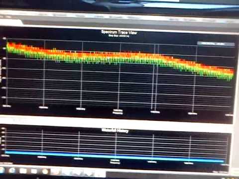
In his latest video Adam shows how the SWR of an antenna can be measured using almost the same low cost equipment. One additional piece of hardware required to measure the SWR is a directional coupler which can be bought on Ebay for about $10 USD.
SWR stands for "standing wave ratio" and is a measure that can be used to tune an antenna for a particular frequency. The closer the SWR is to 1:1 at the designed antenna frequency, the better the antenna will receive (and transmit).
In his video Adam shows how he measures the SWR of an ADS-B antenna which he has built and is selling. His results show that the antenna has an SWR of 1:1.02 at 1090 MHz which is quite good.
DIY Characterize the antenna Retrurn Loss / SWR with the DVB-T SDR
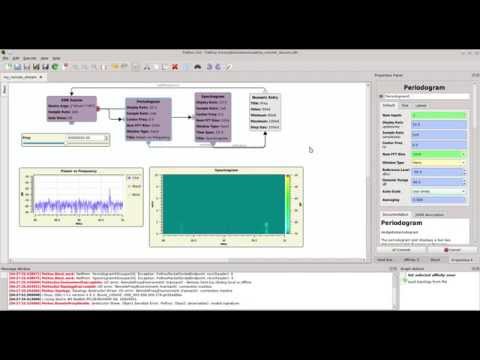
Pothos is a dataflow processing platform that can be used for signal processing through a graphical GUI that works in a similar way to GNU Radio. Over on YouTube the developers have released a tutorial video that shows how to use Pothos to interact with an RTL-SDR dongle. In the video they create a design which shows an RF spectrum and waterfall display.
NOTE: There is now a plugin available for SDR# that will decode TETRA fairly easily. It is still in beta and misses a few features found in telive. Check it out in this post.
TETRA is a trunked radio communications system that stands for "Terrestrial Trunked Radio". It is used heavily in many parts of the world, except for the USA. Recently, a software program called Tetra Live Monitor (telive) was released on GitHub. This software can be used along with the (patched) Osmo-TETRA software to monitor and listen to unencrypted TETRA communications.
Below we show a tutorial on how to listen to TETRA communications using a RTL-SDR RTL2832U software defined radio. This tutorial is based heavily on the telive_doc.pdf file that is written by the author of telive and included in the telive git download. Please refer to that pdf file for further details on how the software works. We have modified their tutorial slightly to make it a little easier to understand. As this code is still under heavy development if you have trouble please check their PDF file for modifications to the procedures.
Most of this tutorial is performed in Linux and we assume that you have some decent Linux experience. We also assume you have some experience with the RTL-SDR dongle and have a decent antenna capable of picking up TETRA signals in your area. If you don't have a RTL-SDR dongle yet see our Buy RTL-SDR dongles page.
Note: As of October 2016 there is now a Windows port of the Telive decoding software available. This may be an option for you if you prefer to run in Windows. More information here.
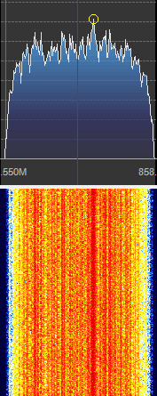
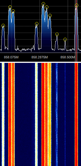
First, we will need to find some TETRA signals. The easiest way to do this is to open SDR# or another program like GQRX and look for them. TETRA signals are continuously broadcasting with a bandwidth of around 25 kHz. In most European countries they can be found at 390 - 470 MHz. In some countries they may be found around 850 MHz or 915 - 933 MHz. There may be several TETRA signals grouped in close proximity to one another. See the example images below.
A Zoomed in TETRA Signal
A Grouping of TETRA Signals Zoomed Out
An example audio clip of a TETRA signal recorded in NFM mode is shown below.
Once you have found some TETRA signals, record their frequencies. Now close SDR#, or whatever software you were using and boot into Linux. In this tutorial we use a 32-bit Ubuntu 14.04 virtual machine running on VMWare Player as our Linux system. Some of the commands may vary if you are using a different system.
The reception process is to essentially record an IQ file of an LRPT transmission using SDR#, reduce the sample rate of the IQ file using audacity and then decode the file using LRPTrx.exe. Then finally the decoded data can be imported into LRPTofflineDecoder to produce an image.
The lab sheet starts off by showing how the RTL-SDR works at a high level, then goes on to explain the function of the R820T tuner chip and RTL2832U chip. The lab then shows a behavioural level model of the RTL-SDR which becomes useful for mathematical analysis. Finally, the lab also explains demodulation theory for FM and FSK signals and sets several lab exercises that involve writing FM and FSK demodulators in MATLAB or Python.
On this episode of Hak5, a popular technology YouTube channel, Shannon does a tutorial on how to get started with the HackRF. The HackRF is a recently released software defined radio similar to the RTL-SDR dongle, but with transmit capabilities.
In the video she shows how to set up the HackRF on Pentoo Linux and GNU Radio. She then shows how to use a GNU Radio program that can receive multiple broadcast FM signals simultaneously. The GNU Radio program is one that is based on Micheal Ossmans GNU Radio video tutorials.
Over on YouTube user w2aew has uploaded a video tutorial explaining how filtering in an upconverter works. In a previous video w2aew explained how a simple upconverter for the RTL-SDR worked and noted that for best performance the upconverter needs three filters, one preselector at the input, one after the local oscillator and one after the mixing stage.
In this video w2aew takes a Nooelec Ham-it-up upconverter which has the three filters mentioned above implemented and scopes the output after each filter to show their effect on an input signal.
#175: Filter functions in an HF Upconverter used with RTL-SDR Dongle Receiver