Over on YouTube Tom from Tom’s Radio Radio Room Show (TRRS) has uploaded a video showing the effectiveness of our broadcast AM (BCAM) filters for cleaning up HF reception. In the video he uses an RSP1 to receive the WWV time signal at 5 MHz and shows that there is some AM signals mixing into the audio. After connecting the BCAM filter the AM signal is gone and WWV comes in clearer.
TRRS #1305 - RTL-SDR.COM MW Filter for Shortwave - Works!
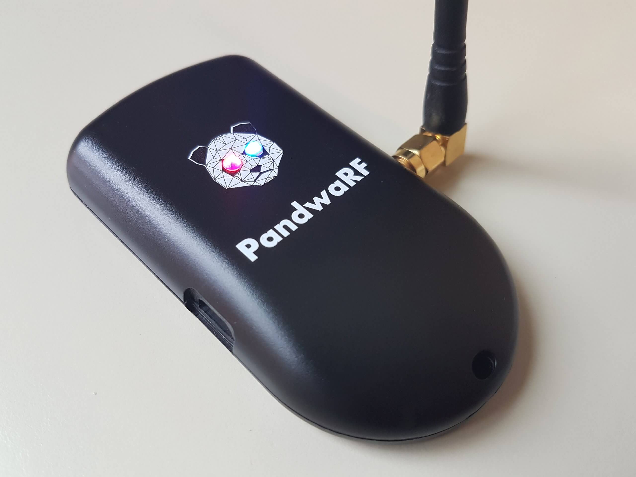
The PandwaRF (formerly known as GollumRF) is an RF analysis transceiver tool that can be very useful for investigating ISM band devices that communicate with digitally modulated RF signals. It can be used for applications such as performing replay attacks, brute force attacks, and other analysis. The RX/TX frequency range of the device is from 300 – 928 MHz, with a transmit power of up to +10 dBm.
The PandwaRF is based on the CC1111 chip which is the same chip used in devices like the Yard Stick One from Great Scott Gadgets (creators of the HackRF). Compared to the YS1 the PandwaRF is essentially the same, but designed to be much more portable, with a built in battery and an Android app that you connect to via Bluetooth. This makes it very useful for taking out in the field as no laptop is required to use it, just a phone or tablet. The PandwaRF can be used just like a YardstickOne when plugged into a PC however.
We should also clarify that CC1111 based devices like the PandwaRF and YS1 are not classed as SDRs. Rather they are RF transceiver chips that can demodulate, decode and transmit a fixed set of digital modulation schemes, such as OOK/ASK, 2-FSK, 4-FSK, GFSK, and MSK. While these devices are not able to receive or transmit any arbitrary signal like an SDR, they make reverse engineering, analysis, replay attacks, brute force attacks etc much simpler for common modulation schemes compared to using an SDR for the same purpose.
Early on in the year PandwaRF sent us a sample of their device for review. Unfortunately during that time their Android software was extremely buggy and we were simply unable to use the device properly. Others reported similar troubles on forums and blog comments. However fast forward to today and it now seems that the Android software is stable and functioning properly.
Replay Attack
PandwaRF Spectrum Analyzer Tool
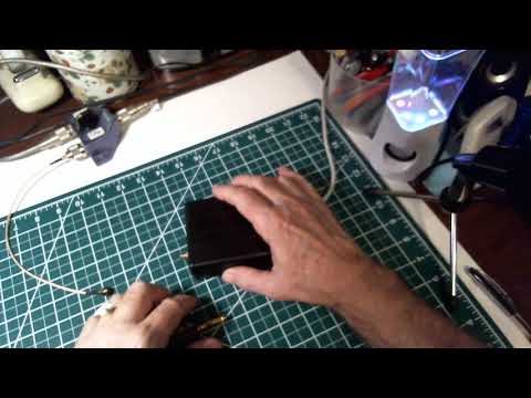
We first tested the PandwaRF on a simple task which was a replay attack. The goal was to record the signal of a cheap wireless RF alarm, and see if we could replay it back. The wireless alarm is controlled with a keyfob.
First we used the Spectrum Analyzer tool in the PandwaRF app to try and get the frequency of the keyfob. The Spectrum Analyzer tool allows you to see about 1.2 MHz of bandwidth. We assumed the signal would be around 433 MHz. After pressing the button a few times the peak showed up at about 433.9 MHz on the spectrum analyzer. The refresh rate of the spectrum analyzer is quite low, so if the signal is not continuous it’s possible to miss the signal, which is we why we had to try several presses before the signal showed. A standard SDR like an RTL-SDR might be better for this initial frequency searching. We confirmed the frequency to be at 433.893 MHz on an RTL-SDR blog V3.
PandwaRF RX/TX Replay Attack Screen
Next we switched to the RX/TX tool. Here you can enter the frequency of interest and set the expected modulation. We know that this device is ASK/OOK modulated, so we chose this setting. You also need to set the data rate. If you don’t know this value then the app has a data rate measuring tool. So we just pressed on the Measure button, and then pressed a button on the remote until it converged to a data rate of 5,121.
Next you need to set the ‘desired payload’. This is how many bytes long the packet is and determines how long the capture is. As we were unsure we simply set it to 250 bytes to ensure that a longer capture was taken. The PandwaRF will keep on receiving until it receives the desired payload of 250 bytes or is stopped manually. Setting it longer allows us to capture a longer signal, and ensure that the replayed signal is received. For this alarm device it is okay if the same signal is played multiple times in a short time frame.
The final setting is the RX Frame length. This determines how many bytes will be captured before transferring the data to Android. So for example, if you set the desired payload to 100 Bytes, and the RX Frame length to 52 bytes, then in total you will capture 104 Bytes of data. The PandwaRF can only transfer in 14, 33, 52, 71 or 90 bytes, so select one that is closest to a multiple of your desired payload.
Finally we pressed on ‘Sniff’ and pressed the ‘bell’ button on the remote. The PandwaRF detected the signal and recorded the data. Now pressing Xmit replays the signal successfully causing the alarm bell to sound.
Replayed and Original Signal received with an RTL-SDR
Brute Force Attack
Brute force settings
The PandwaRF can also be used as a brute forcing tool. With cheap alarms the alarm code is relatively short, so can be brute forced in a matter of minutes. The PandwaRF already had a preset mode for our cheap Forecum door alarm, so we simply selected this mode and started the brute force. It gave an estimated brute force time of 28 minutes, which is the time it takes to run through every possible alarm code.
More advanced brute force settings
The PandwaRF app currently supports the Idk and PT2262 chipsets, as well as some models of DIO, Extel and Forecum house alarms. If the device that you want to brute force is not yet in their database, then you’ll probably need to do some analysis first on the PC with an SDR. Software like Universal Radio Hacker and DSpectrumGUI are good tools for this. Once you know the structure of the data, then you can program PandwaRF to perform the brute force attack.
Note that their newer ‘PandwaRF Rogue’ product is supposed to be significantly faster at brute forcing. For example the Android software gives us a estimated duration of 28 minutes with the standard PandwaRF, and only 3 minutes with the Rogue.
The Rogue is also able to brute force 32 bit codewords with zero delay in between transmissions. The standard PandwaRF has a minimum delay of 100 ms which can really slow things down. It also allows for function mask bit skipping, enable more brute force patterns and can split the brute force attempt into several steps. Also as we’ve seen from their videos the Rogue has more pre-set commercial devices built into its app.
So if brute forcing is your main use for the PandwaRF then it seems to make sense to get the Rogue. Unfortunately the Rogue is significantly more costly, coming in at 990 euros, vs 145 euros for the standard PandwaRF. Of course you could still use the standard PandwaRF on a PC with tools like rfcat to perform a faster brute force attack as well, just like you would with a YardstickOne.
PandwaRF Brute Force attack as seen by an RTL-SDR
Javascripting
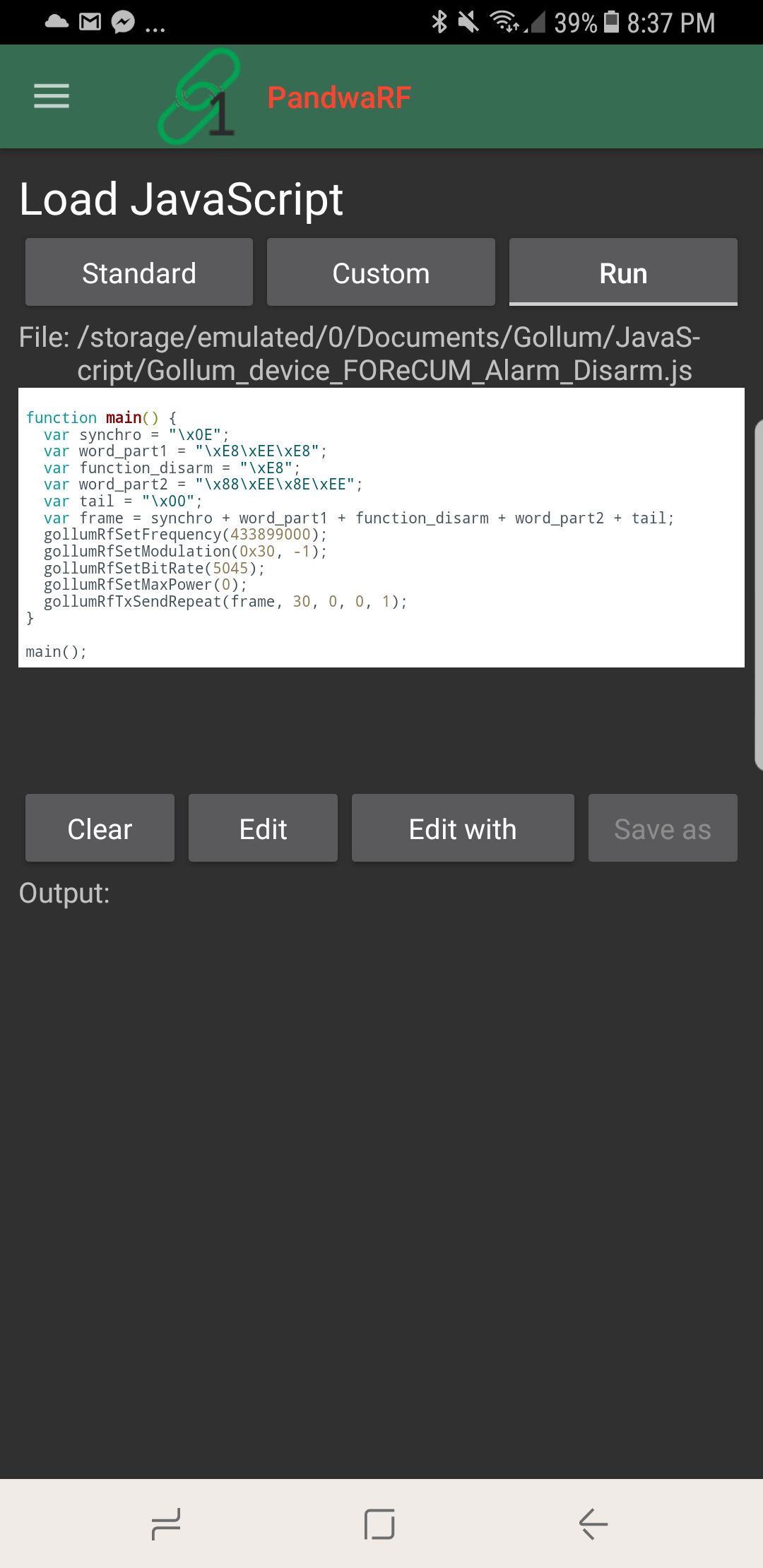
Javascript in PandwaRF
If you need more powerful analysis or TX capabilities, then the PandwaRF can be controlled in Javascript code. For example, you might have already reverse engineered a device, and simply require the PandwaRF to transmit the correct code to replace a remote control. You could also create a jammer with this.
The code runs on the Android device and not on the PandwaRF, so each RF command generates a bluetooth transfer which can be quite slow. They write this is why they have created a specific brute force implementation in the app, so that they can run their native brute force code on the PandwaRF itself, which is must faster than transferring the RF command for every brute force step.
Conclusion
Overall the PandwaRF is a very handy tool for doing replay and brute force attacks while in the field. It can also be converted back into a PC based CC1111 device, like a Yardstick One simply by plugging it into a computer with a USB cable so you’re not missing out on that functionality either.
Compared to the Yardstick One the cost is a bit more, with the Yardstick One costing $99 USD at most outlets, and the PandwaRF costing 145 Euros (~$173 USD). So it is probably only really worth it if you are doing field testing.
That said, now that the PandwaRF software seems stable it is an excellent tool for investigating wireless devices in a simpler way compared to with an SDR. An SDR is still much more powerful, but tools like this simplify the process significantly. The best set of tools for reverse engineering would be a SDR combined with a device like this.
In the future it looks like they plan to implement new features such as De Bruijn (OpenSesame) attack’s and rolling code attacks and we look forward to testing those out.
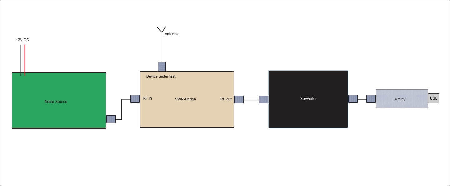
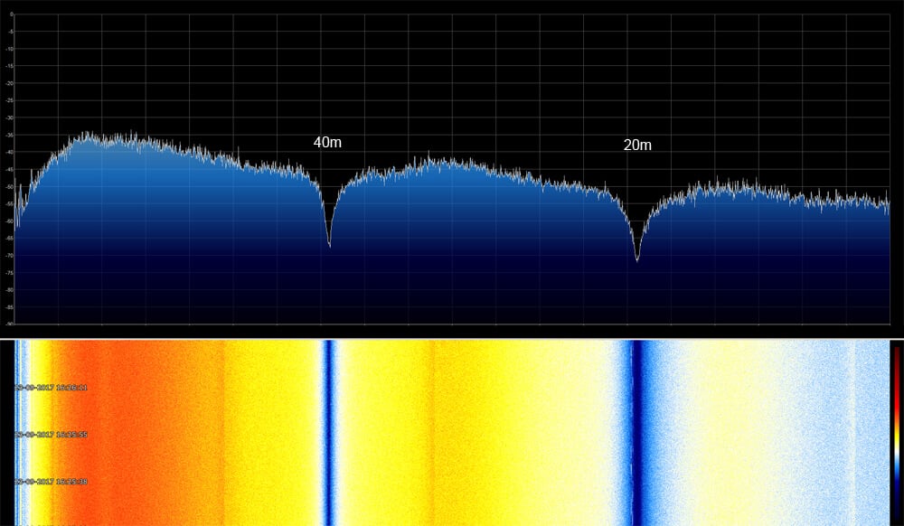
By connecting the output of the noise source to the SWR-bridge input, and the antenna to the DUT port the return loss or SWR of the antenna can be measured with the Airspy. To get a wider than 10 MHz view of the spectrum Anders uses the SpectrumSpy software for the Airspy which is a spectrum analyzer application that allows you to view any bandwidth that you like. With the Airspy, noise source and antenna all connected correct to the SWR-Bridge significantly notches in the spectrum show up in SpectrumSpy. These notches are the resonant points of the antenna. Visually seeing these notches allows you to fine tune the length of the antenna elements for best SWR.
How to connect it all upSpectrumSpy showing the resonant notches at 40m and 20m.
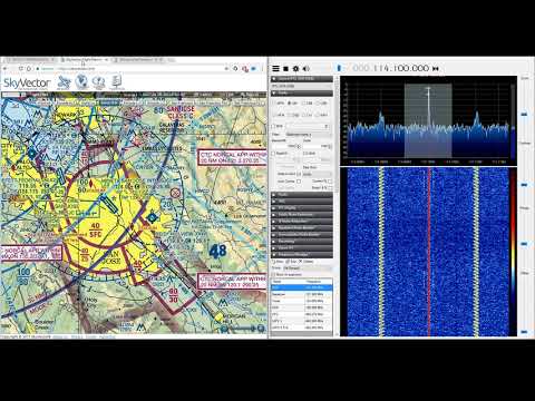
Over on YouTube user RedWhiteandPew has uploaded two videos showing what VOR and ILS signals look like in SDR# with an RTL-SDR dongle. VOR and ILS are both radio signals used for navigation in aviation.
VOR stands for VHF Omnidirectional Range and is a way to help aircraft navigate by using fixed ground based beacons. The beacons are specially designed in such a way that the aircraft can use the beacon to determine a bearing towards the VOR transmitter. VOR beacons are found between 108 MHz and 117.95 MHz.
RedWhiteandPew writes:
Here I am picking up the VOR beacon from KSJC. The coolest part is at the end of the video. I believe the signal moving back and forth is caused by the Doppler effect, because VORs transmit their signals in a circular pattern. The VOR wiki article has a GIF that shows how it works here https://en.wikipedia.org/wiki/VHF_omn…. If you play and pause the video at different points before I zoom in, you can see that the two signals on the side are the opposite phase.
Listening to a VOR on a Scanner || RTL-SDR Dongle
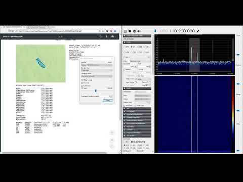
ILS stands for Instrument Landing System and is a radio system that enables aircraft to land on a runway safely even without visual contact. It works by using highly directional antennas to create four directional lobes (two in the horizontal plane, two in the vertical) that are used to try and ensure the aircraft is centered and leveled on the approach correctly. The ILS frequencies are at 108.1 – 111.95 MHz for the horizontal ‘localizer’, and at 329.15-335.0 MHz for the vertical ‘glide slope’.
RedWhiteandPew writes:
Here I have tuned into one of KSJC’s ILS frequencies. You are able to hear the faint identifier beeping transmitting its ISL ID code which is ISJC. For comparison, I used to morse code translator website.
The reason I am hearing ISJC and not ISLV even though they are on the same frequency is because the localizers transmitting the signal are directional along the length of the runway. Since I am located to the south east of the airport, and I am within its transmitting beam, I am able to listen to it on a scanner.
Listening to an ILS Localizer (RTL-SDR Dongle)
If you’re interested in these signals then this previous post about actually decoding them might be of interest to you.
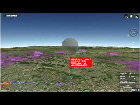
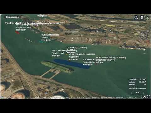
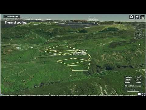
Over on YouTube user pascal poulain has uploaded a short video that shows a timelapse of the flight path of a weather balloon in Cesiumjs as it rises and falls, as well as a time lapse of a marine tanker docking, with the signals received with an RTL-SDR. In a third video pascal also shows a visualization of glider flights tracked via FLARM and the Open Glider Network which also obtains most of it’s data through RTL-SDR contributors.
Cesiumjs is a tool similar to Google Earth. The main difference is that it works on a wider array of devices through a web browser without the need for any plugins. It is often used for visualizing data on the globe. An example of some of its many demos can be found here.
We’re not sure what tools pascal used, but over on GitHub there is a tool called airtrack which can be used together with dump1090 to display flights in real time on Cesiumjs.
Illustration of 3D realtime tracking of weather sonde.
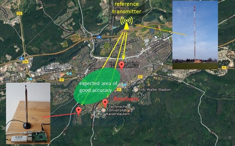
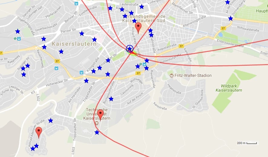
Back in August we posted a number of videos from the Software Defined Radio Academy talks held this year in Friedrichshafen, Germany. One of those talks was by Stefan Scholl, DC9ST and titled Introduction and Experiments on Transmitter Localization with TDOA. This was a very interesting talk that showed how Stefan has been using three RTL-SDR + Raspberry Pi setups to locate the almost exact position of various transmitters with time difference of arrival (TDOA) techniques. TDOA works by setting up at least three receivers spread apart by some distance. Due to the speed of radio propagation, the transmitted signal will arrive at each receiver at a different time allowing the physical origin point of the signal to be calculated.
Now over on his blog Stefan has created a very nice writeup of his work with RTL-SDRs and TDOA that is definitely worth a good read. He first explains the basics of how TDOA actually works, and then goes on to explain how his RTL-SDR based system works. He discusses the important challenges such as transferring the raw data, synchronizing the receivers in time and the signal processing required.
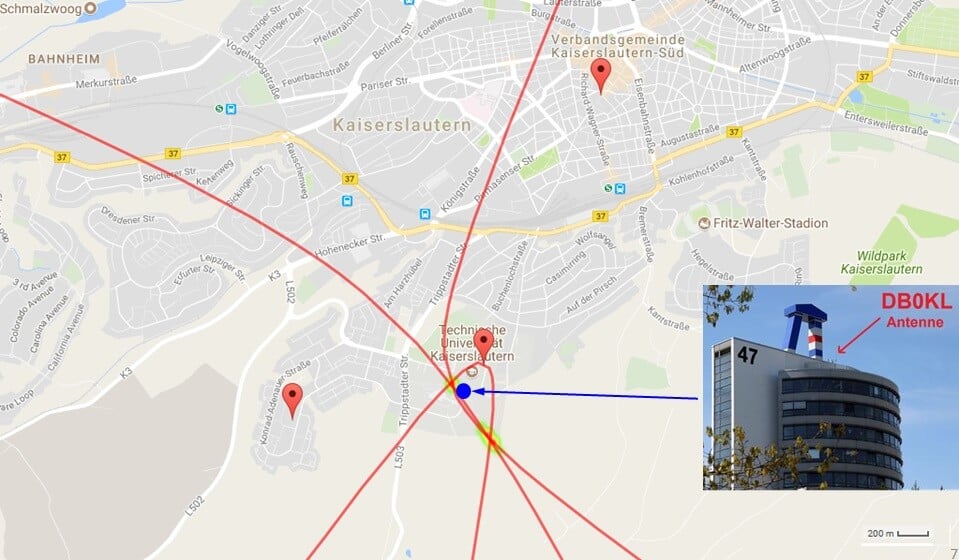
Stefans TDOA System
He tested the system on various transmitters including a DMR signal at 439 MHz, a mobile phone signal at 922 MHz, an FM signal at 96.9 MHz and an unknown signal at 391 MHz. The results were all extremely accurate, locating transmitters with an accuracy of up to a few meters.
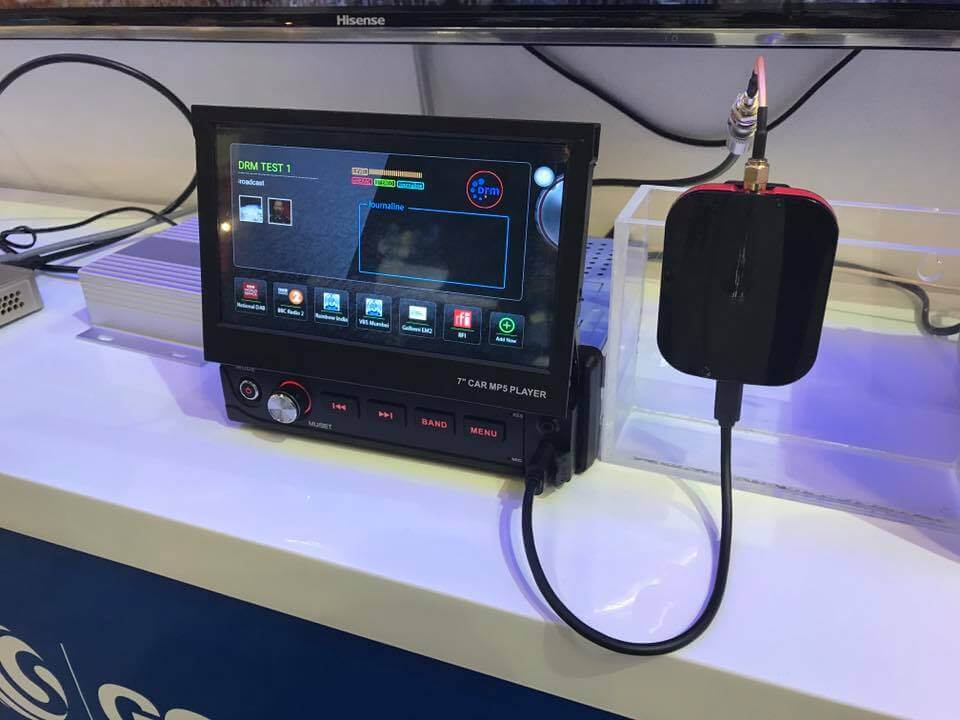
Over on the SWLing Post blog we’ve seen news of this new SDR based car radio called the Gospell GR-227. Gospell is a Chinese manufacturer of various broadcast consumer radio products including DRM receivers. It is intended to be an adapter for your car that lets you listen to digital broadcast stations such as DAB/DAB+ on VHF and DRM on UHF, but it can also be used for standard AM and FM reception. From the product sheet it looks like it will simply plug into you car USB port, and output audio through that port into your cars head unit. Control of the unit is through an Android app.
There doesn’t seem to be anything stopping someone from using this outside of a car though, so perhaps depending on the price and software hackability available it might make a good PC or Raspberry Pi based HF receiver for all modulation types too.
Over on the Gospell Facebook page are images showing the Gospell running at IBC 2017 and next to other upcoming SDR based digital broadcast receivers like the Titus II.
Gospell SDR Connected to a Car Radio Head Unit
No word yet on a release date or pricing. The press release reads:
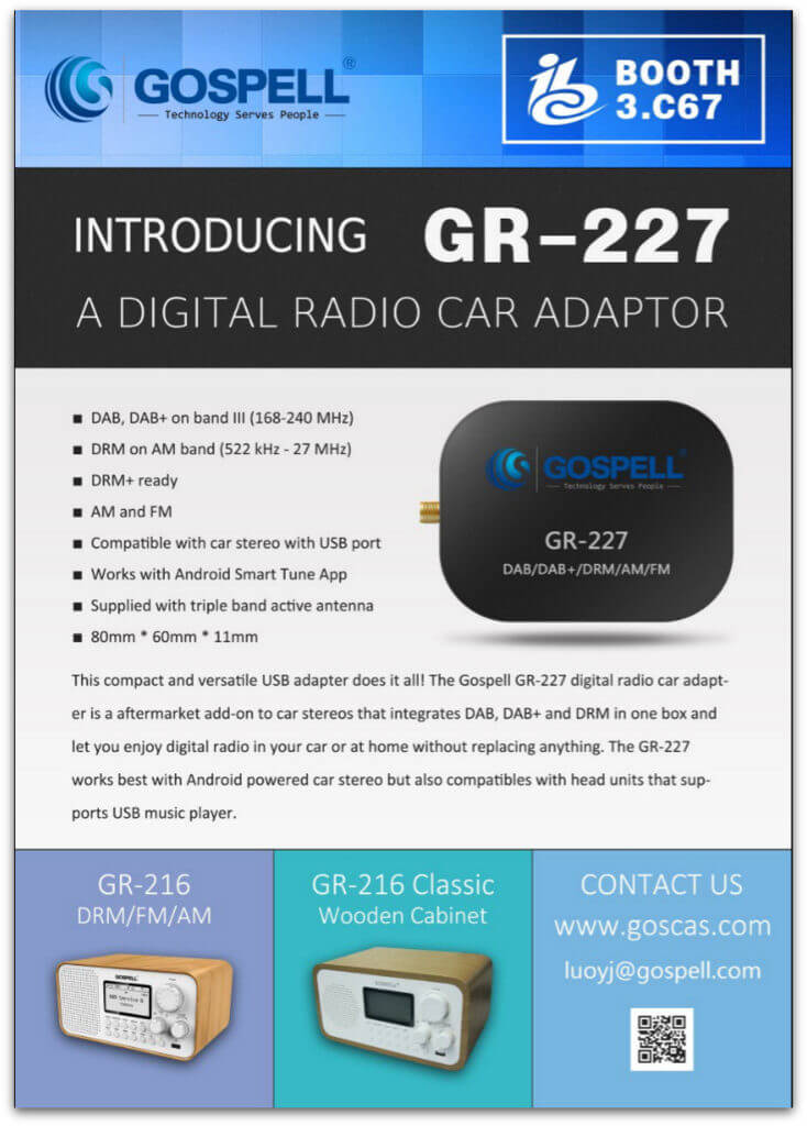
Chengdu, China, September 04, 2017 – A new adaptor specifically designed for in-car use that simplifies digital radio on the road will be introduced at IBC by Gospell.
GR-227 is a small, low-cost adaptor that acts as an aftermarket add-on to car stereos receiving high-quality digital broadcast programs and data application, and serving it to the car audio system over a USB cable. Based on software defined radio technology, GR-227 is compatible with DAB, DAB+, DRM and is DRM+ ready. It is also powerful enough to support digital audio decoding such as extended HE-AAC (xHE-AAC).
GR-227 literally works with any kind of car stereos with a USB port. Our patent pending technology allows the adaptor to behave like a thumb drive when plug into a USB port and makes it compatible with most of the music players not only in car but also for home use.
To make the most of GR-227, the Gospell Smart Tune App for Android has been included to add more features. When partnered with an Android powered car stereo, the App not only allows for playback of the broadcast audio program but data application which brings much fun to car entertainment.
By connecting the supplied triple band active antenna which can be attached to the windscreen through the SMA antenna connector, the reception in DRM, FM and DAB bands can be significantly improved, offering maximum flexibility between different broadcasting standards.
Installing the plug-and-play GR-227 adaptor to your car is easy and doesn’t require changing your car stereo. It is one of the easiest ways to upgrade your car radio to digital without replacing anything.
The Gospell’s aftermarket car adaptor range starts with USB model but more will follow to support more car stereo types.
Haochun Liu, DRM director, Gospell, said: “By leveraging SDR, we can now combine multiple broadcasting standards together to offer flexibility and cost advantages, coupled with easy installation without the necessity of buying a new car stereo as in traditional solutions.”
For additional information, please visit www.goscas.com or contact Gospell sales at [email protected].
About Gospell
Founded in 1993, Gospell Digital Technology Co Ltd (GOSPELL). is a private hi-tech enterprise with R&D, manufacturing, business consultancy and planning, trade, delivery, project implementation and after sales service, acting as a complete DTV and triple-play solution provider for Digital TV/OTT related projects. Headquartered in GOSPELL INDUSTRIAL PARK at Chenzhou, Hunan Province for CPE related production manufacturing, GOSPELL also has its office in Shenzhen for business/marketing management and administration, in Chengdu for R&D and headend/transmitter system production/debugging and Customer Service Center, and in 12 cities in China as well as international offices in India, Africa and Mexico.
Earlier in the month we posted about Adrian M’s video that showed his QRadioLink software running on Android with an RTL-SDR. QRadioLink is a digital amateur radio voice decoder and encoder, that currently supports modern digital voice codecs like Codec2 and Opus. It’s compatible with a wide range of SDRs including the RTL-SDR, as well as TX capable SDRs for transmitting.
Over on YouTube Adrian M has recently uploaded a new video showing a comparison of QRadioLink receiving SSB, NFM, Codec2 and Opus voice signals at the same initial power levels. The results show that the digital modes are generally much clearer and static free even at low TX levels. He writes:
The Linux SDR transceiver application QRadioLink uses here an RTL-SDR dongle for reception. The QRadioLink transmit chain is using an USRP B200 with output power set at about half the maximum. The Codec2 digital mode works down to a low CNR (6 dB) where even SSB is hard to copy. The Opus mode provides good voice quality at a level where analog narrow FM is noisy. The code for QRadioLink is fully open-source, licensed under GPLv3, and can be found on Github, where it’s undergoing development. Bug reports, patches and suggestions are welcome.