Setting up Propagation Triggered Spectrum Recording

Over on the SDRplay blog and forums OH2BUA has been sharing how he has set up ‘propagation triggered recording’ by continuously monitoring JT65/JT9 signals with his SDRplay. The idea is that you leave the radio on receiving all night, and set it to automatically start recording IQ files if good propagation conditions occur as determined by the locations received from the JT65/JT9 signal. This may yield some interesting far off stations that can be listened to in the morning, whilst weeding out hours where nothing but commonplace local stations are heard. The software is a simple Windows batch file that works together to coordinate HDSDR and JTDX. It should work with any HF capable SDR.

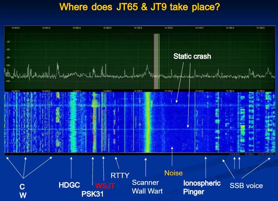
JT65/JT9 are weak signal propagation HF modes (also known as WSJT modes) that can be decoded all around the world, even with very weak reception thanks to strong digital error correction. They can often be used to determine propagation conditions by determining where successfully decoded messages are being sent from.

OH2BUA writes:

I have made a set of scripts and other files which can be used to build a system which monitors JT65/JT9 (digital modes) amateur radio traffic on 160m/1.8MHz band, and if nice propagation to area you are interested in exists, a MW-BC-band recording is started. When the conditions fall off, the recording is stopped.

There is an attached zip-file containing all the necessary stuff. Sorry this is a windows thing – but easily portable also for linux. Create C:\bat\ and drop all there. Have a look, starting from README.

The default example is to start a MW-band I/Q-recording, if North American ham signals are heard – but it is fully modifiable according to your target when in comes to areas, bands, schedules etc.

The files are available as an attachment to the forum post.

Where WSJT Modes are located (slideplayer.com/slide/4310450)

rtlmic: Wireless Microphone Receiver for RTL-SDR

Over on GitHub a new program called rtlmic has recently been uploaded. The program descriptions reads: 

rtlmic is a multichannel FM microphone receiver/demodulator for RTL-SDR cards. It outputs realtime audio to JACK.

Basic usage is simply:

$ rtlmic [channel 1 frequency] [channel 2 frequency]…

This program may be able to be used as a replacement for wireless microphone base stations at events. The software allows you to capture as many channels as your CPU can handle, within the active bandwidth of the RTL-SDR. There are also settings for tweaking the companding ratio and tau, deemphasis tau and FM deviation all of which affect the output audio and can be used to optimize the frequency response of the microphone.

The audio outputs directly to Jack audio which is an audio piping API, which simply routes the audio out to wherever you choose it to go.

A typical wireless microphone base station and microphones.

CNxROOT Two Posts: How to Build an RTL-SDR Server with OpenWRT, Creating a GSM BaseStation with OpenBTS and a USRP

Recently security researcher cnxroot wrote in to let us know about two of his posts that may be of interest to readers. The posts are written in Chinese, so please use Google Translate to read them in English – it translates okay to some extent.

The first post shows us how to run the RTL-SDR on an OpenWRT capable router server. OpenWRT is a Linux firmware/OS that can be installed on several compatible router devices which extends the usefulness and features of the router. Since it is running Linux the RTL-SDR drivers can be installed onto it, and then rtl_tcp can be run, providing a remote RTL-SDR.

The second post is a bit more advanced. It is about creating a pseudo GSM base station with a USRP SDR and intercepting IoT devices which connect over GSM/GPRS. The post shows how to set up OpenBTS which can be used to create a base station.

RTL-SDR running on an internet router with OpenWRT.

A Homemade PCB Log-Periodic Antenna

Ham radio enthusiast and RF designer Marco Cardelli (IZ5IOW) recently wrote in and wanted to share his PCB log periodic antenna design which he has been using together with RTL-SDR dongles. Log periodic’s are very wideband directional antennas that can easily be printed onto a circuit board.

Marco’s antenna covers a frequency range of 900 MHz – 2600 MHz.  The original principal focus was for EMI/EMC measurements, but Marco writes that it works perfectly fine for microwave experiments on the 23 and 13cm bands of wi-fi links. Marco currently uses this antenna for reception of microwave beacons. Currently there are no designs or plans on his website for the antenna, but we suspect that he will put them up soon.

If you’d rather purchase an antenna like this instead building one, then we’ve seen in the past good reviews from the PCB antennas available from wa5vjb at www.wa5vjb.com.

The wideband PCB log-periodic antenna.
Return Loss of the PCB Log Periodic antenna.

Radio For Everyone New Posts: Building an ADS-B Station, Easy Homemade Beginner ADS-B Antennas

Akos the author of the radioforeveryone.com blog has recently added two new articles to his blog. The first post is a comprehensive guide to setting up your own ADS-B station. The guide focuses on creating a system that is easy to use, has good performance and is value for money. In the post he shows what type of computing hardware is required, what software can be used and what RTL-SDR dongles work best. He also shows what choices are available when it comes to amplification and filtering to improve signal reception and goes on to talk a bit about adapters and the antennas that work best for him.

BuildingADS-Bstation
Building a ADS-B station

 In the second post Akos shows more on how to build your own beginners antennas for ADS-B reception. The post focuses on showing how to modify the stock magnetic mount antenna that comes with most RTL-SDR dongles, and how to build a half-wave ‘spider’ antenna entirely out of coax cable. The post is full of easy to follow images which make it great for beginners.

EDIT: It’s been pointed out in the comments by antenna experts/enthusiasts that the 1/2 wave ground plane antenna described by Akos in his tutorial may not be technically correct. A 1/2 wave antenna has a huge impedance which requires some sort of matching. Without matching there is going to be about 10 dB of loss due to the mismatch, and so the antenna will perform poorly. We recommend sticking with a 1/4 wave design, which is essentially the same as Akos’ 1/2 wave ground plane antenna, just with the element lengths halved.

Running a 1G Mobile Phone Network with a HackRF

First generation (1G) mobile phone technology was brought out in the 80’s and was an unsecured analogue system. These days 1G technology is completely phased out in favor of digital standards like 2G (GSM), 3G and 4G LTE and so those old 1G handsets are now useless. However, at Shmoocon 2017 presenter Brandon Creighton delivered a talk where he showed how to use a TX capable SDR like a USRP or HackRF to create your own home 1G system that allows those old brick phones to be useful once again.

The actual video of the conference talk won’t be available online until about half way through the year but the blurb read:

AMPS, the first widely deployed cellular network in the US, was old enough that it had been designed by pre-breakup Bell, yet robust enough to survive for decades in service. Unlike LTE or even GSM, it was also a protocol simple enough to be described in a fairly short specification; if you wanted to you could listen to calls with a TV tuner (or modified phone).

This is a talk on the design and implementation of gr-amps, a set of GNU Radio blocks that can turn a TX-capable software-defined radio into a base station for AMPS devices–including that brick phone in your basement. No background in SDR is necessary to follow along (but it doesn’t hurt).

Expect detours into near-forgotten phreaker history: the weaknesses that enabled phone cloning, the efforts of wireless carriers and the US government to fight exploitation, and more.

The GNU Radio code to run your own AMPS (1G) system is available on GitHub.  It has been tested on a USRP and HackRF.

lethalweaponcellphone

[Also seen on Hackaday]

Hacking a Danfoss Wireless Thermostat with an RTL-SDR

Over on his blog Andy writes how he wanted a smart way to control his central heating system with a Raspberry Pi and Arduino microcontroller. He discovered that if he could reverse engineer his existing wireless thermostat then he would have an easy way to control the boiler in his house and with that a smart controller could be made. By reverse engineering the thermostat he also avoids the need to rig up his own control system.

The existing thermostat wireless receiver is a Danfoss RX2. In order to reverse engineer the protocol Andy opened up an older that one he had and saw that it used an Infineon TDA5210 RF receiver chip. Armed with this part number he was able to look up the datasheet and determine the operating frequency. Then by using an RTL-SDR he captured some packets while pressing buttons on the thermostat transmitter and piped the audio file into audacity, where he was able to clearly see the digital waveform.

Andy then wrote a Python program using the ‘wave’ library, which allowed him to easily read binary values for a .wav file. With his code he was able to extract the data from the signal and determine the preamble, sync word, thermostat ID and the instruction code (on/off/learn).

In a future post Andy hopes to show us how he’ll use an RF69 module with an Arduino to actually control the thermostat using the reverse engineered packet knowledge.

Danfoss Wireless Thermostat and a Received Binary Waveform in Audacity

Showing the HF Interference Problem from Ethernet over Powerline Devices

Over on our YouTube channel we’ve uploaded a new video that shows how bad the interference from Ethernet over Power devices can be. Ethernet over Power, Powerline Networking, Powerline Communications or ‘HomePlug’ is a technology that allows you to use any of your household power outlets as an internet Ethernet port, completely eliminating the need for runs of Ethernet cabling. They are capable of high speeds and can be used anywhere in the house assuming the two plugs are on the same power circuit.

Unfortunately these devices tend to wipe out almost the entire HF spectrum for anyone listening nearby. As household powerline cables are not shielded for RF emissions they radiate in the HF spectrum quite heavily. In the video we demonstrate what the HF spectrum looks like with one of these devices used in the house. The particular device used was a TP-Link brand adapter, and a WellBrook Magnetic Loop antenna was used outdoors, with the null facing the house. An Airspy R2 with SpyVerter was used to view the spectrum.

The video shows that even when the network is idling there are several brief bursts of noise all over the spectrum. Then when a file is downloaded almost the entire spectrum is completely wiped out.

Interestingly from the video it appears that the amateur radio frequencies are actually carefully notched out and those frequencies remain relatively clean. Most manufacturers of these devices appear to have worked with the ARRL to please ham radio enthusiasts, but SWLers will likely be in trouble if any of these devices are used in your house or neighbors house.

How Ethernet/Internet over Powerline Can Wipe out the HF Band