Combining the Bandwidth of two HackRF’s

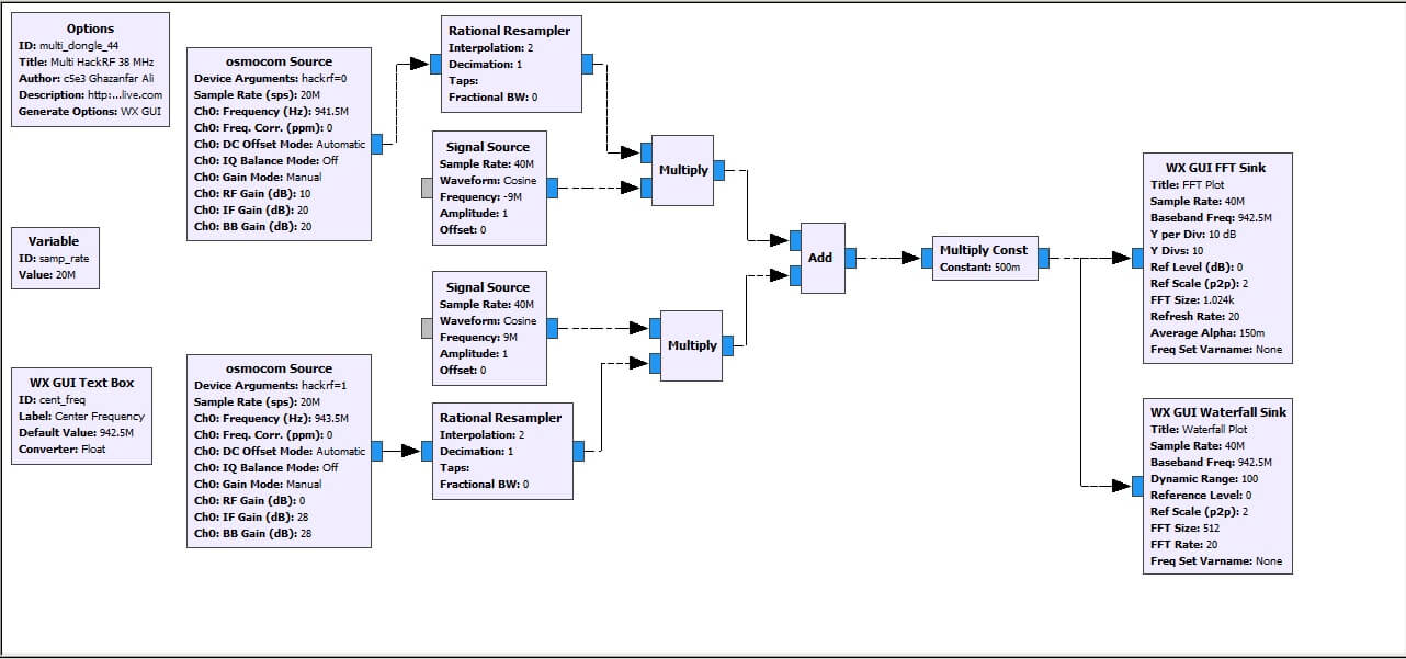
RTL-SDR.com reader Syed Ghazanfar Ali Shah Bukhari from the Frequency Allocation Board in Pakistan recently emailed us to let us know a trick he's found which lets you combine the bandwidths of two HackRF software defined radios in GNU Radio. Syed's program is based on Oliver's flowgraph that we posted previously, which was used to combine the bandwidth of two RTL-SDR dongles.

Syed also sent us the GRC file to share which we've uploaded here.

He writes:

I have used grc flow graph of Oliver as mentioned in the link :-
https://www.rtl-sdr.com/combining-the-bandwidth-of-two-rtl-sdr-dongles-in-gnu-radio and modified it to be used with 2 HackRF Ones. I also shifted the two bandwidths inward by 1 MHz instead of 0.2 MHz to make a smooth continuation for a 38 MHz spectrum. Unfortunately one of my HackRF Ones has its RF Amp burnt up so I adjusted its IF and BB gain to have same noise floor as that of other HackRF One. It's really awesome. I am sending you the diagram and grc file. The attached image is showing complete GSM900 downlink spectrum (38 MHz) in my area with active 2G and 3G signals.

September 2018 Update:

An rtl-sdr user with nick JAAP had some query pertaining to calculation of center frequency of each HackRF. The values I used were a bit erroneous. If you the previous flow graph I sent you, the center frequencies for both HackRFs are same in the SDR source box. That should be different for both with a 20 MHz difference between the two. Some spectrums started repeating themselves on those values. I have improved the flowgraph using variables and equations to remove the logical bug. I have added a slider for bandwidth cropping that can be used for test pupose only to understand the concept behind the frequency shifting and cropping of spectrum of both HackRFs. I have attached the new grc file and the image. Gain values can be adjusted as per user requirement and sensitivity of your own SDRs. I am working on grc which will show a spectrum using 5 rtl-sdrs and two hackRFs thus combining BWs to give a span of 50 plus MHz.

Update GRC File available here.

Multi HackRF Spectrum
Multi HackRF GRC flowgraph

SDRuno Updated to V1.1: Now supports up to 2.4 MSPS for the RTL-SDR

SDRuno is the official software for the SDRplay RSP software defined radio. Recently they’ve released version 1.1 which contains various new features and bug fixes for the RSP. The SDRuno Cookbook by NN4F & KD2KOG has also accordingly be updated with information about the new features.

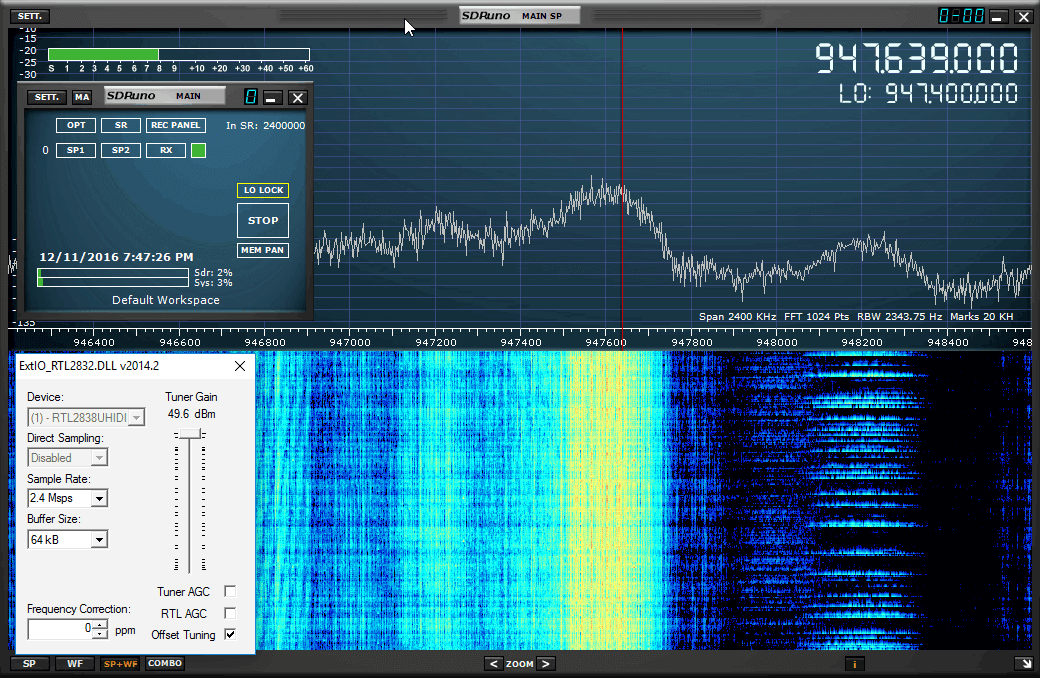
In addition they’ve also now increased the previous 0.96 MSPS sample rate limit which was enforced for all third party radios running via EXTIO drivers. The new limit is 2.5 MSPS (with 2.4 MSPS being the limit for the RTL-SDR). This is great news for RTL-SDR users as SDRuno for the RTL-SDR is now almost as functional as in other SDR software like SDR#, HDSDR and SDR-Console. The change log is pasted below:

Version 1.1 (11th November 2016)
Bug Fixes

  • 1.04.1 – fixed issue where highlighted filter wasn’t always the one loaded.
  • Waterfall in combo mode now flows the same direction as other modes

Updates (RSP only V1.1)

  • Tighter integration of RSP controls
  • Calibrated power measurement
  • Automatic S-Meter calibration
  • SNR meter
  • dBm scale for both SP1 and SP2 windows
  • Automatic frequency calibration
  • Support for IARU S-Meter standard
  • Zoom to VFO button in SP1 window
  • More improvements to AGC scheme
  • More improvements to DC offset compensation scheme
  • Reversed default mouse wheel scroll direction
  • Waterfall in combo mode direction can be reversed in the same way as other modes
  • Added extra frequency step sizes
  • LSB / USB filter presets back to being the same
  • USER filter preset renamed to DIGITAL
  • Support for both gain and gain reduction displays
  • Updated hardware driver – now reports as SDRplay device

Updates (EXTIO only V1.05)

  • maximum bandwidth changed to 2.5MHz
SDRuno Version 1.1 Running a RTL-SDR at 2.4 MSPS

The ThumbNet N3 is now Shipping

The latest RTL-SDR receiver from Thumbnet, the Thumbnet N3 is now shipping out. Back in October we received a sample of one of their prototypes and found it to have a very low noise floor since they have replaced the 1.2v switching regulator with a linear regulator.

ThumbNet is a company that is hoping to provide low cost satellite deployments, and make use of volunteers around the world with RTL-SDR’s to help track them. The RTL-SDR’s and antenna kits are provided to schools and educational institutions for free by ThumbNet, in exchange for students setting up and monitoring a satellite tracking station.

In their release email they wrote:

ThumbNet would like to send a very large “Thank You!!” to all of you who have supported us by purchasing one of our surplus N3 SDR receivers, and we wanted to take a second and let you know that we’re excited to announce that the N3’s have left the factory and will begin shipping.

The support has been tremendous and we have a backlog of many hundreds of receivers to get out. We will be working extremely hard, over the coming days to get them all delivered as quickly as possible (Orders will be shipped in the order they were received.).

Don’t forget that there are accessories in the ThumbSat Store (http://www.thumbsat.com/thumbnet-sdr-hardware/thumbsat-store-4 ) that may be of value to you, such as adapters, cables or power supplies to let you get the maximum performance from your ThumbNet N3. 

A handful of independent tests have been done on the Qualification Models of the N3, and the results have been quite positive.  If interested, you can read some of the reviews at the following links.

RTL-SDR.com – https://www.rtl-sdr.com/rtl-sdr-com-quick-review-of-the-thumbnet-n3-prototype/

RTLSDR4EVERYONE – http://rtlsdr4everyone.blogspot.com/p/thumbnet-n3.html

Thank you again for supporting ThumbNet and we hope the N3 exceeds all of your expectations!!

The Thumbnet N3 with its metal case add on.
 

Demuxing Frames and Generating Images from the GOES Weather Satellite

In his latest two posts Lucas Teske continues with his series about receiving and downloading weather satellite images from the GOES satellites. In past posts he’s show us how to receive the signal with a satellite dish and Airspy or RTL-SDR (part 1), how to demodulate the signal (part 2), and how to extract frames from the demodulated signal (part 3). Lucas has recently completed his series with parts 4 and 5 having just been uploaded.

In part 4 Lucas shows how to parse the frames and get the packets which will ultimately be used to generate the weather image files. His post explains how to de-randomize the frame data which is initially randomized to improve performance, how to add Reed Solomon error correction, how to demux the virtual channels and the packets and finally how to save the raw packet.

The packet structure

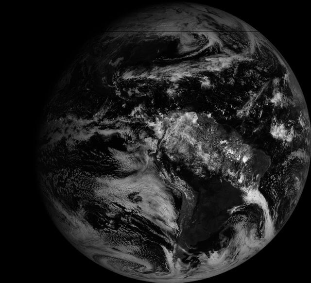
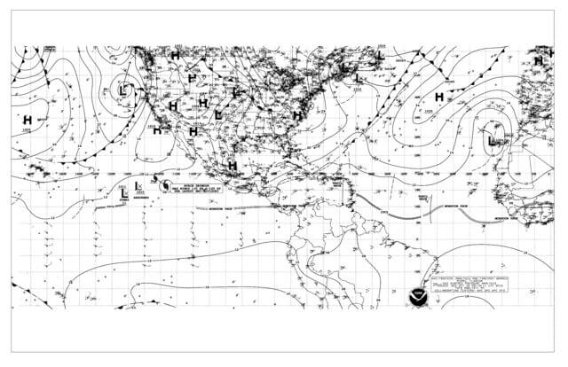
In part 5 Lucas shows us how to finally generate weather satellite images from the GOES satellites. He notes that there is a problem with the LritRice compression method used by NOAA, because the library is currently broken on Linux. So he made a workaround which involved making a Windows application that runs through Wine for decompressing the data. Once the files are decompressed he uses the xrit2pic program which can open the generated .lrit files and convert them into images.

In the future Lucas mentions that he will write a user guide to his LRIT decoder, and make the whole decoding process more user friendly for people who do not care so much about the actual decoding process. Below are some images that Lucas was able to receive with his system.

GOES Full Disk Image of the Earth
Weatherfax (WEFAX) Image

Mile Kokotov’s SDR Overview and Dynamic Range Explanation

Mile Kokotov (Z33T) has been working on creating an overview page of some of the most popular software defined radios and software applications. In the past we’ve featured Mile’s videos several times on our blog and his page ties all the videos together nicely with text. On his page he briefly reviews the different types of RTL-SDR dongles as well as the Airpsy and SDRplay.

One very useful page he’s put together is his explanation of the “dynamic range” concept, which is probably the most important characteristic when it comes to a radio. According to Miles description dynamic range measures the ability of a radio to “receive very weak and very strong signals at the same time, without overloading”. His page also explains how decimation in software can help improve the dynamic range without needing to improve the hardware.

Mile’s page is not yet 100% finished, so we advise you to keep an eye on it for new information.

Explaining dBFS (decibels relative to full scale)

Solving APRS Interference Issues with a Bandpass Filter and Coax Notches

John, DK9JC N1JJC wanted to set up an RTL-SDR APRS packet iGate. APRS stands for “Amateur Packet Reporting System”, and is a type of packet radio communications system used by Amateur Radio operators. They often use them to transmit short messages, weather sensor updates, and for vehicle tracking. An iGate allows APRS messages to be transmitted over the all world via the internet like so RF->iGate RX->Internet->iGate TX->RF.

When trying to receive the APRS packets John discovered a problem. He discovered that there was a very strong 100kW broadcast FM and 50kW DAB transmitter on a transmission tower in line of sight of his antenna. The strong signals were overloading the dongle and completely wiping out the APRS packets that he was trying to receive at 144.8 MHz.

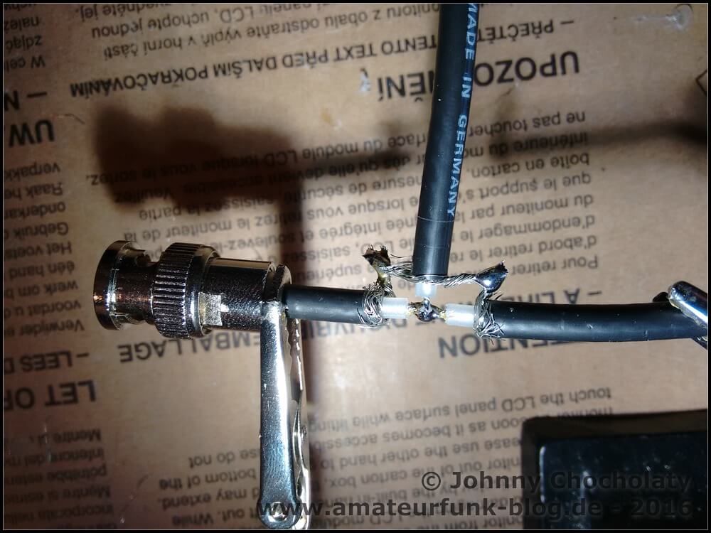
First John tried a simple bandpass filter with 0.8 dB insertion loss and 20dB attenuation. The filter still wasn’t enough, so he went and made a several coax notch filters to take out each of the interfering signals. A coax notch filter is simply a length of coax connected via a “T” junction to the main coax cable. This creates a notch of attenuation at a frequency depending on the length of the notching coax. With these notches combined with the bandpass filter he was finally able to receive APRS packets.

A coax notch filter
A coax notch filter

Building a Frame Decoder for the GOES Weather Satellite

Yesterday we posted about Lucas Teskes (@lucasteske) success in building a demodulator for the GOES weather satellite. Before that he also showed us how to build an antenna system to receive GOES with an Airspy or RTL-SDR dongle.

Today Lucas continues with part three of his series on GOES decoding. This time he shows how he has built a frame decoder to process the output of the demodulator, and also gives us a link to his code. The decoder is written in C code. Lucas’ post explains how to sync the frame by detecting the preamble, perform convolution encoding to generate a parity and help correct any errors, and decode the frame data.

In part four Lucas will show us how to parse the frame data and extract the packets which will eventually form an image file of the earth.

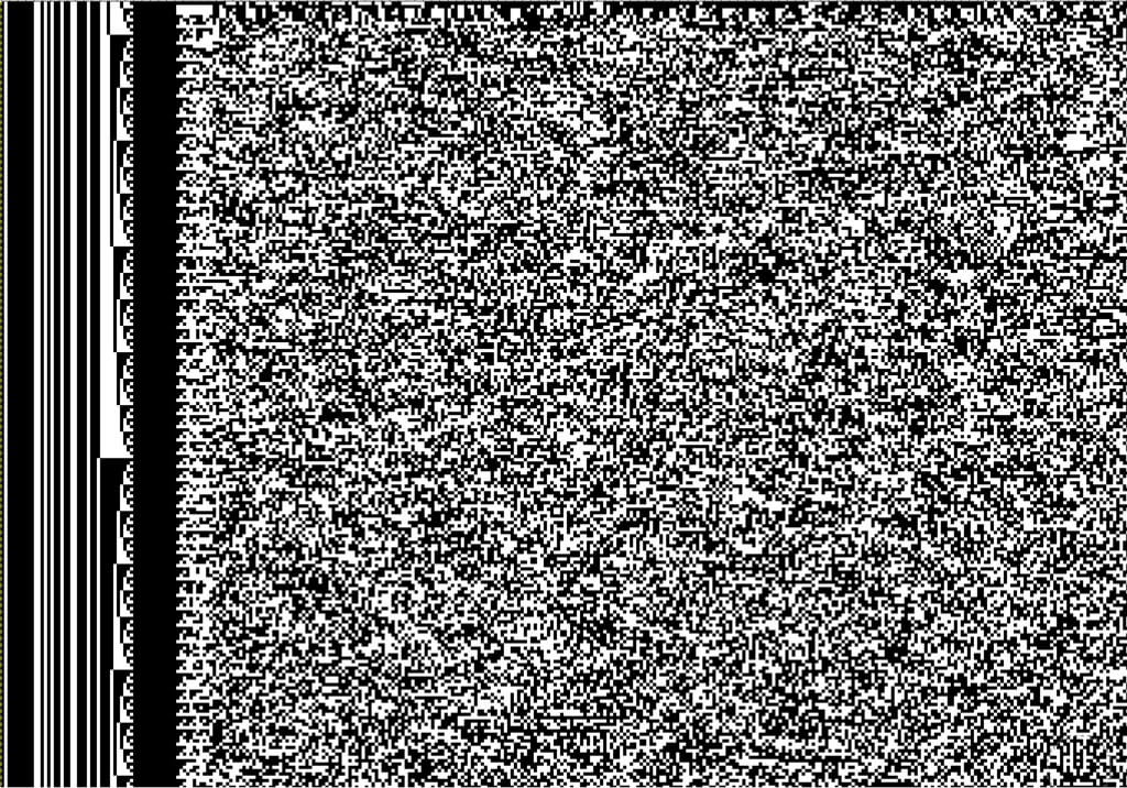
A decode frame viewed as an image. This shows the syncword pattern and frame counter.

Helping to Raise Funds for the Canadian Centre for Experimental Radio Astronomy (CCERA)

Patchvonbraun (aka Marcus Leech) is one of the pioneers in using low cost SDR dongles for amateur radio astronomy experiments. In the past he’s shown us how to receive things like the hydrogen line,  detect meteors and observe solar transits using an RTL-SDR. He’s also given a good overview and introduction to amateur radio astronomy in this slide show.

Now Marcus and others are starting up a new project called the “Canadian Centre for Experimental Radio Astronomy (CCERA)”. They write that this will be an amateur radio astronomy research facility that will produce open source software and hardware designs for small scale amateur radio astronomers. Currently they also already have a hydrogen line telescope set up, which is producing live graphs and data. From their recent posts it also looks like they’re working on building antennas for pulsar detection. They also have a GitHub available for any software they produce at https://github.com/ccera-astro.

Currently CCERA is looking for donations over at gofundme, and they are hoping to eventually raise $25k. They write:

About CCERA:

Radio astronomy is one of the most important ways to observe the cosmos. It is how we learned about the existence of the afterglow of the big bang (the cosmic microwave background), it is how we observe huge swaths of the universe that are otherwise obscured by dust. Most of what’s going on out there can’t be seen with visible light.

Astronomy has traditionally been one of the areas in science where dedicated non-professionals have continued to make an enormous contribution to the field. Optical astronomy requires little more than a telescope and knowledge.

Radio astronomy has, up until recently, required a lot more skill and resources. However, technology has advanced enough that small groups could be making serious contributions to radio astronomy. With the right sorts of software and information, many dedicated non-professionals could be doing good work in the area, and CCERA intends to help make that a reality.

CCERA will be producing open source software and hardware designs to help non-professional and professional radio astronomers alike, documenting them, and helping people get up to speed so that they can use these powerful tools themselves. Our GitHub repository is: https://github.com/ccera-astro

CCERA will also be operating its own radio astronomy facilities, initially in Ontario, Canada. These will serve as a test-bed for our own designs, as a place for us to train interested people in the operation of low cost radio astronomy equipment, and will also be used for real radio astronomy work. All our data will be publically-available.

About us:

Roughly 10 years ago, I and a number of others started a project to restore a large, historic, satellite earth station antenna at Shirleys Bay in Ottawa. Our goal was to bring the dish back on-line for use in amateur radio astronomy, research, and importantly, educational outreach about science, and radio astronomy.

The project came to a sudden end back in 2013/14 when the owner of the dish (The Canadian Space Agency) needed to dismantle it to make way for other occupants of the site.

However, during that period, we became fascinated with the possibilities that opening up radio astronomy to skilled non-professionals could bring.

Since then, our group has been working on another far lower cost project to build our own a specialized radio telescope somewhere in the Rideau Valley area. Many of our group live in the area, and Marcus lives in Smiths Falls. With good attention to the usability of our designs and open publication of our tools under appropriate open source licenses, our work should be replicable by others. We thus hope to kick off a new era in non-professional radio astronomy.

What we need the money for:

We’ve secured a small office in the Gallipeau Center outside of Smiths Falls, and will be able to erect our specialized antenna arrays over the coming year.

While we have a lot of the equipment we’ll need, we’ll have more equipment to buy, and on-going expenses to cover, including rent, insurance, miscellaneous mechanical construction materials (lumber, metal, etc). We also need to cover expenses relating to incorporation as a not-for-profit.

Our goal is to provide a test facility for small-scale radio astronomy research, and to develop techniques that allow small organizations and educational institutions to run their own small-scale radio astronomy observing programs.

If we are successful, in addition to making our designs and software available under open source licenses, we’ll be holding regular public lectures, host training seminars, host school groups, etc. We will also produce videos of our work for those who cannot visit us directly in Ottawa. We want to make some of the techniques of “big science” accessible and understandable.

We can’t do it without the help of the public, who, we hope, will become our students, collaborators, and ongoing supporters.

We will also make all of our data available to the public without fee or restrictions. We believe in openness in scientific endeavours, even small ones such as ours.

Marcus Leech
(tentative) Director
Canadian Centre for Experimental Radio Astronomy
www.ccera.ca

If you have even a passing interest in radio astronomy please consider donating, as CCERA’s work may open up exciting new possibilities for amateur radio astronomers with low cost SDR dongles.

The pulsar antenna being built at CCERA.