Rebooting the ISEE-3 with USRP Software Defined Radios

The ISEE-3 is a exploratory spacecraft that was launched in 1978 and placed in an orbit around the sun. It was mission was to study the interaction between solar wind and the earth's magnetic field and was later the first spacecraft to pass through the tail of a comet. NASA suspended communications with the spacecraft in 1997 and it was last heard of in 2008.

Recently there has been interest in rebooting the spacecraft and bringing it back into an earth orbit. Once safely in orbit the spacecraft's science instruments would be made publicly available for educational purposes. Unfortunately, the RF communications hardware and knowledge that was used to interface with the spacecraft has long been lost.

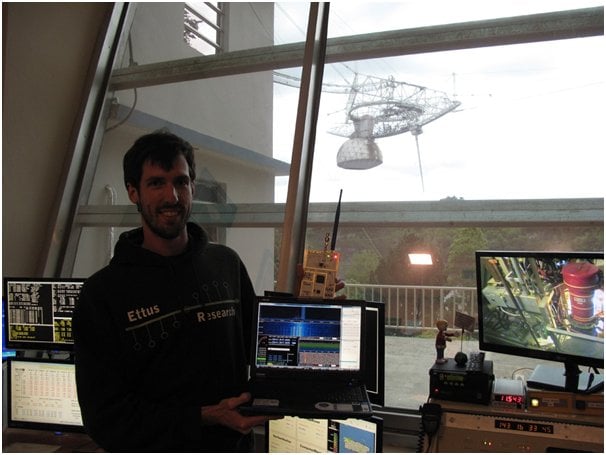
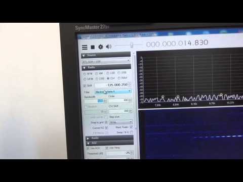
Luckily, the scientists and engineers at Ettus were able to devise a plan that would use the world's largest single dish radio telescope at Arecibo connected to some of their USRP N210 SDR radios to contact the probe. The USRP N210 is an advanced software defined radio that sells for around $1700 USD. Using their setup together with GNU Radio and the spacecraft's documentation from NASA they were able to make contact with the spacecraft and fire the thrusters. They have yet to actually correct the trajectory which will bring it back to earth, but they hope to be able to do that soon.

The ISEE-3
The ISEE-3
USRP at the Arecibo Dish

Low Cost Hydrogen Line Telescope using the RTL-SDR

Amateur radio astronomer Y1PWE has uploaded a pdf document describing how he created a low cost hydrogen line telescope using an RTL-SDR dongle (links under heading 2. H-Line Receiver) . Hydrogen atoms randomly emit photons at a wavelength of 21cm (1420.4058 MHz). Normally a single hydrogen atom will rarely emit a photon, but since space and the galaxy is filled with many hydrogen atoms the average effect is an observable RF power spike at 1420.4058 MHz. By pointing a radio telescope at the night sky, a power spike indicating the hydrogen line can be observed in a frequency spectrum plot.

Y1PWE created a radio telescope using a quad 22 element yagi antenna, several LNA's and filters and an RTL-SDR dongle and laptop. Using this setup he can capture some raw IQ data from the RTL-SDR and then use an FFT averaging program to produce some plots. In his plots the hydrogen line is clearly visible.

Radio Telescope Overview
Hydrogen Line Plots
Hydrogen Line Plots
Quad Yagi Array
Quad Yagi Array

RTL-SDR Easy HF Dongle Mod

Over on YouTube user crookedninja5 has uploaded a video showing what he calls the “Easy HF dongle mod”. The mod involves soldering a wire from Pin 1 on the RTL2832U chip to the static protection diode near the antenna input. At the same time he also uses the modified RTL-SDR dll file for SDR# which enables the “no hardware mod” direct sampling mode.

Using this mod he is able to get decent coverage of 0 – 14.4 MHz.

SDR Shortwave Radio Mod "easy HF dongle mod"

Using an RTL-SDR to help open a Gated Community

Tomasz lives in a gated community, but as he doesn’t own a car he wasn’t given access to a gate remote control. This made it difficult for him to have friends who have cars visit him. So he decided to use an RTL-SDR to receive, capture, analyze the gate signal which is transmitted at 433 MHz and then copy the signal to use with his own homemade transmitter.

First Tomasz used his RTL-SDR with SDR# to capture a few sound files of the gate remote which transmits at 433 MHz. Then he viewed the sound waveform’s in Audacity, a free audio editing program. Just by looking at the waveform he was able to determine that the signal was On-Off Key (OOK) modulated and that each frame of the transmission was the same, meaning that no security scheme was used.

Next he wrote down the transmission parameters that he learned from his analysis and built a simple 433 MHz transmitter which he connected to a microcontroller. After programming his microcontroller to send a copied signal he was able to open the gate.

433 MHz Gate Remote Received on the RTL-SDR

Making a Cheap Noise Figure Indicator with an RTL-SDR

Amateur radio hobbyists Frank Schmaling (DL2ALF), Wolf-Henning Rech (DF9IC) and Alexander Kurpiers (DL8AAU) have uploaded a pdf document containing slides which show how they made a cheap noise figure indicator using an E4000 RTL-SDR dongle. A noise figure indicator can be used to check the noise figure of various components used in RF applications.

The hardware of the device consists of an RTL-SDR, a MGZ 30889 preamp, a noise source, a 28V boost converter to power the noise source and a serial to USB converter to control the noise source. They also created their own custom software in C# to go along with the hardware.

Their results showed that this setup was comparable to a professional noise figure test set.

RTL-SDR based Noise Figure Indicator
Noise Figure Indicator Software

Receiving Russian Long Range Navigation System with an RTL-SDR, Upconverter and Mini-Whip Antenna

Over on YouTube user Mile Kokotov has uploaded a video showing his reception of the ALPHA Russian Long Range Navigation System on Very Low Frequency (VLF) in Macedonia using an RTL-SDR, Ham-it-up upconverter and a Mini-Whip active antenna.

Mile also uses a band pass filter and notch filter to improve the dynamic range of the RTL-SDR. Additionally, in the video he shows a comparison between a large delta loop antenna and the mini-whip active antenna which shows better performance by the mini-whip.

RTL-SDR on VLF (ALPHA Russian Long Range Navigation System receiving in Macedonia with MiniWhip)

Hak5: Using A RTL-SDR To Learn About The GSM Network Around You

The popular YouTube electronics channel Hak5 has uploaded a video showing how they analyzed GSM signals using an RTL-SDR, Wireshark and Airprobe. In their video they use parts of our analyzing GSM tutorial and explain and show visually how to set up all the software.

Using these methods they were able to receive GSM data from a base tower and see various system information.

Using A RTL-SDR To Learn About The GSM Network Around You, Hak5 1621

Update to the RTL-SDR Transmitting at 1270 MHz

In our previous post we featured a video by OH2FTG which showed an RTL-SDR transmitting at 1270 MHz. Now OH2FTG has written in to give us some more information about the RTL-SDR transmitter. He has done a short writeup explaining how it’s done on his website. It turns out that the RTL-SDR is actually capable of transmitting a FSK morse beacon using it’s leaky oscillator.

In the video, code written by another ham OH2EAT is used. OH2EAT’s code essentially changes the frequency on the transmitting RTL-SDR at up to 300 times a second using a modified driver. This is used to create a Frequency Shift Keyed (FSK) transmission.

The modulating transmitter code is not yet available as it is not yet ready for release. In the future OH2FTG hopes to build an amplifier to boost the signal output for further experiments.