Thank you to Carl Reinemann for writing in and sharing with us that the Meteor M2 LRPT decoder by Oleg (Robonuka) was recently updated. The Russian Meteor M2-3 weather satellite was launched in June of this year and is currently the only operational Meteor M2 satellite in the sky. It transmits images at 137 MHz in the digital LRPT format.
To receive it a simple V-Dipole antenna and RTL-SDR is usually sufficient. And to decode it software like SatDump or M2_LRPT_DECODER combined with the Meteor Demodulation Plugin for SDR# can be used. Instructions for the latter are available on HappySats instructional page.
Regarding the update Carl writes:
Thanks to Oleg (Robonuka), Happysat and Usradioguy have been testing the new decoder for about 6 weeks now, and it is ready to go!
The stability of the processing has been improved: The decoder is now more likely to produce stable results, even when there are errors in the input data.
The procedure for generating RGB and calculating GEO in the error-handling block has been improved. Now, the decoder's processing is considered unfinished until the GEO calculation is completed.: This means that the decoder will now wait until the GEO calculation is finished before generating the RGB values. This helps to prevent errors and produce more accurate results.
Exception errors fixed: Some errors that were previously causing the decoder to crash have been fixed.
AutoClose=yes by default: This means that the decoder will now automatically close when it is finished decoding. This can be helpful for saving resources and preventing memory leaks.
80K is much more stable: The decoder is now more stable than before. This means that it is less likely to crash or produce unexpected results.
Overall, these changes make the decoder more reliable and easier to use.
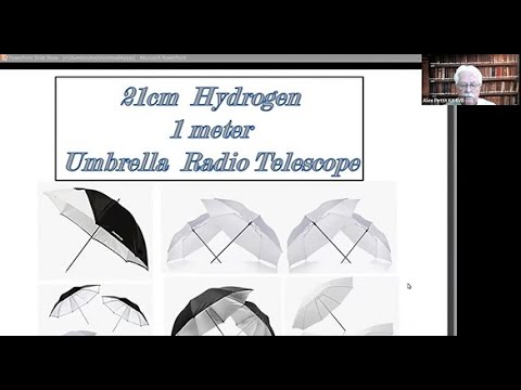
One talk by Alex Pettit describes how to build a radio telescope from a an umbrella and some "Faraday fabric" which is copper cloth. The results show more than adequate performance for the cost, making this an affordable and easy entry to radio astronomy.
Alex Pettit - Umbrella Antennas
Another video presented by Dr. Wolfgang describes building small to medium sized radio telescopes. He explains how small radio telescopes less than 3 meters in size can work well for receiving the 21cm Hydrogen line, and how SDRs are the best choice of receiver for them. Many examples of small dish installations are shown.
Dr. Wolfgang Herrmann: Building Small/Medium Size Radio Telescopes
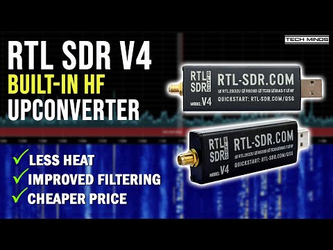
Over on his TechMinds YouTube channel Matt has uploaded a new video showing him testing out the new RTL-SDR Blog V4 dongle that we released a couple of weeks ago. In the video Matt explains the differences between the RTL-SDR Blog V3 and V4 dongles, and then goes on to show the Blog V4 dongle in action. He finishes by comparing reception between the V3 and V4, noting the reduced interference on the HF bands due to the lack of Nyquist folding from direct sampling.
We note that the first batch of the RTL-SDR Blog has currently sold out, but a new larger batch will be ready to go on sale around the end of September. So please keep an eye on the blog's main page and store if you are interested in picking one up.
RTL SDR V4 - Now with Built-In HF Upconverter + More Features
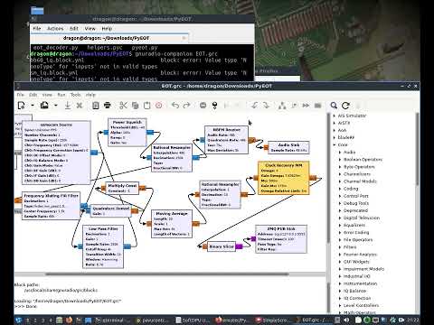
Over on his YouTube channel Aaron who created and maintains the DragonOS SDR Linux distribution, has uploaded a video demonstrating how to use an RTL-SDR and SoftEOT/PyEOT to decode North American wireless train telemetry.
HOT (Head of Train), EOT (End of Train) and DPU (Distributed Power Unit) telemetry is sent from various parts of a train and contains information about things like voltages, brake line pressure and to monitor for accidental separation of the train.
In his video Aaron uses his DragonOS Linux distribution, SDR++ with an RTL-SDR Blog V4 dongle and the SoftEOT and SoftDPU decoders. SoftEOT and SoftDPU are both Windows programs, however Aaron shows how to use WINE to run them in Windows. Later he shows how to use an alterative decoder called PyEOT which is based on GNU Radio.
GNU Radio conference talks are generally about cutting edge radio research topics and applications that involve the use of GNU Radio, a popular DSP framework for SDRs. If you are interested, previous years talks can be found on the GNU Radio YouTube channel.
The talks at GRCon23 will be livestreamed on YouTube for free, and we have pasted the links to each days live stream link below. We recommend activating YouTube notifications on each video so you won't miss the start.
NOTE: We have found more stock of R828D chips, so the V4 should be in production hopefully until the end of 2025.
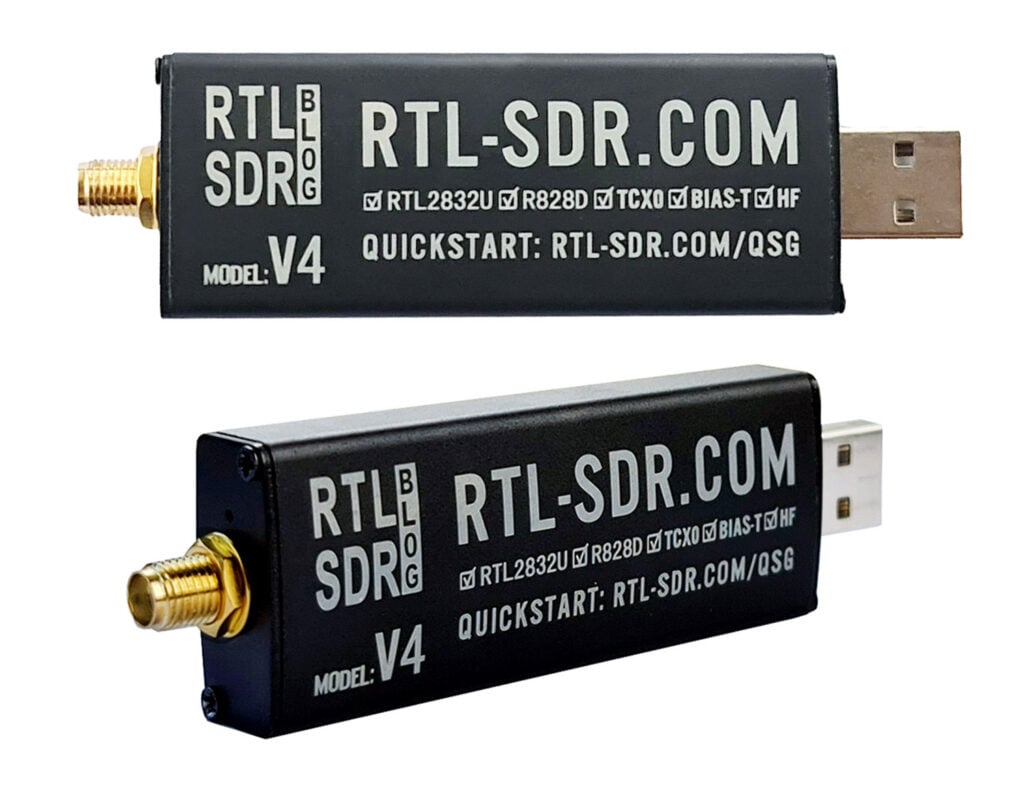
We're happy to announce the first release of our new RTL-SDR Blog V4 dongle which is based on the R828D tuner chip. The pricing is US$39.95 for the V4 dongle with antenna set, and US$29.95 for the dongle only, including free shipping to most countries.
Currently we are only shipping this model from our warehouse in China and the initial production batch is small and so we are limited in stock. However, now that we have confirmed that production of the first small batch of V4 has gone very well, we will be ramping up production, and stocking Amazon USA within 1-2 months as well.
The V4 comes with several improvements and changes that are listed below.
Improved HF Reception. Now uses a built in upconverter instead of using a direct sampling circuit. This means no more Nyquist folding of signals around 14.4 MHz, improved sensitivity, and adjustable gain on HF. Like the V3, the lower tuning range remains at 500 kHz and very strong reception may still require front end attenuation/filtering.
Improved filtering. The V4 makes use of the R828D tuner chip, which has three inputs. We triplex the SMA input into three bands, HF, VHF and UHF. This provides some isolation between the three bands, meaning out of band interference from strong broadcast stations is less likely to cause desensitization or imaging.
Improved Filtering x2. In addition to the triplexing, we are also making use of the open drain pin on the R828D, which allows us to add simple notch filters for common interference bands such as broadcast AM, broadcast FM and the DAB bands. These only attenuate by a few dB, but may still help.
Improved phase noise on strong signals. Due to an improved power supply design, phase noise from power supply noise has been significantly reduced.
Less heat. Due to the improved power supply design the V4 uses slightly less current and generates slightly less heat compared to the V3.
Cheaper price! The price of the R860 chip which is used in the V3 and most other RTL-SDR brands increased significantly at the beginning of 2023 which is part of the reason as to why RTL-SDR dongles have been increasing in price recently. For the V4 we are making use of an existing stockpile of R828D chips which are now priced cheaper than new productions of the R860. In a time when high inflation keeps pushing prices up this is incredibly welcome.
There are some other minor changes including a new bias tee LED and a small cutout hole in the enclosure so it's easy to tell when the bias tee is on.
Of course the same innovations that we brought in with the V3 are still implemented such as the sleek conductive black metal enclosure which works as a shield and doubles as a heatsink, a thermal pad to sink heat away from the PCB, 1PPM TCXO, SMA connector, USB noise choking and improved ESD protection.
The V4 however does come with some disadvantages compared to the V3 that need to be noted:
Due to the increased filtering there can be an average of 2-3 dB less sensitivity on some bands. Please see the MDS measurement graph below for the full picture.
The V4 requires the use of our RTL-SDR Blog drivers. Our RTL-SDR blog drivers are on GitHub. Please be sure to follow the installation instructions on the quickstart guide carefully. In most cases using our drivers simply means running our install-rtlsdr-blog.bat file, or replacing a dll file. (UPDATE: The default Osmocom branch now supports the RTL-SDR Blog V4, as does most other software)
The V4 is a Limited Edition Design. The R828D tuner chip is completely out of production now and the number of units we can produce is limited by the number of chips held by our contract manufacturer in China. They have indicated that there should be enough stockpile for about a years worth of production. (UPDATE: We have sourced more chips and should be able to continue production at least well into 2025)
Because of these tradeoffs we will continue selling the V3 alongside the V4.
More About the V4 Design
The R828D
The core change on the RTL-SDR Blog V4 design is the change from the R860 tuner chip to the R828D tuner chip. The R828D was previously a more expensive chip, however with the huge price increases on the R860 which came in effect at the beginning of the year we have decided to make use of existing R828D stock which is now cheaper than the R860.
The R828D is very similar to the R820/R860 and shares much of the same circuitry. However, instead of just one input, it comes with three switchable inputs. We have used these three inputs together with a triplexer to create a dongle with some extra input filtering. In the past there have been some R828D based dongles on the market, but all designs are based on TV receiver circuits. Because our design is different, you will need to use our RTL-SDR Blog driver branch which has added compatibility for our R828D design.
Also please note that because the R828D chip stock is limited, and it is no longer in production, the V4 design is also a limited design which we expect to be able to sell for about a year.
HF Design
The HF design consists of a SA612 double-balanced mixer circuit with front end filtering, which is connected to the 28.8 MHz oscillator that is also used for the tuner and RTL2832U chip. This means that HF frequencies are upconverted by 28.8 MHz. Our drivers handle this upconversion seamlessly, so you just need to tune to 0 - 28.8 MHz in order to receive HF. There is no need to set any offset.
An upconverter design also means that unlike direct sampling full gain control is available, and also there is no folding of signals across 14.4 MHz due to Nyquist.
Adding Basic Input Filtering
One of the main problems with RTL-SDR dongles is overload from strong broadcast stations such as broadcast FM, broadcast AM and DAB. By using a triplexer circuit we can make use of the three inputs on the R828D tuner chip to provide some filtering. The triplexer splits the input signal into HF (0 - 28 MHz), VHF (28 MHz - 250 MHz), and UHF+ (250 MHz - 1.766 GHz). This means that interference from something like strong broadcast FM at 88-108 MHz is more isolated when we are tuned to the HF and UHF bands.
We've also made use of the open drain pin on the R828D (which does not exist on the R860) to implement a simple switchable notch filter for the main problem broadcast bands. These notch filters cover broadcast AM, broadcast FM and DAB, and reduce them about an additional 5-10 dB. By default the notch turns ON when tuned out of these bands, and is turned OFF when tuned within them.
In terms of sensitivity, the disadvantage of adding more filtering is that it can reduce sensitivity in some bands. However, sensitivity of the RTL-SDR is usually not a problem in most situations, as we're usually limited by desensitization from strong out of band signals as mentioned above. If sensitivity is a priority an LNA such as our wideband LNA should be used anyway, for any RTL-SDR brand or model. Any front end LNA will totally dominate the sensitivity figures, making any sensitivity measurements of the RTL-SDR itself irrelevant.
Revised Power Design
The revised power design makes use of a more modern LDO with significantly better power supply noise rejection which results in much lower phase noise seen on strong narrow signals. There are also some PCB tweaks to reduce internally produced noise. The LDO improvement also has the effect of reducing power usage and lowering heat.
Other Changes
We've also added an LED to the bias tee, so it's easier to tell if it has been activated in software.
MDS Measurements
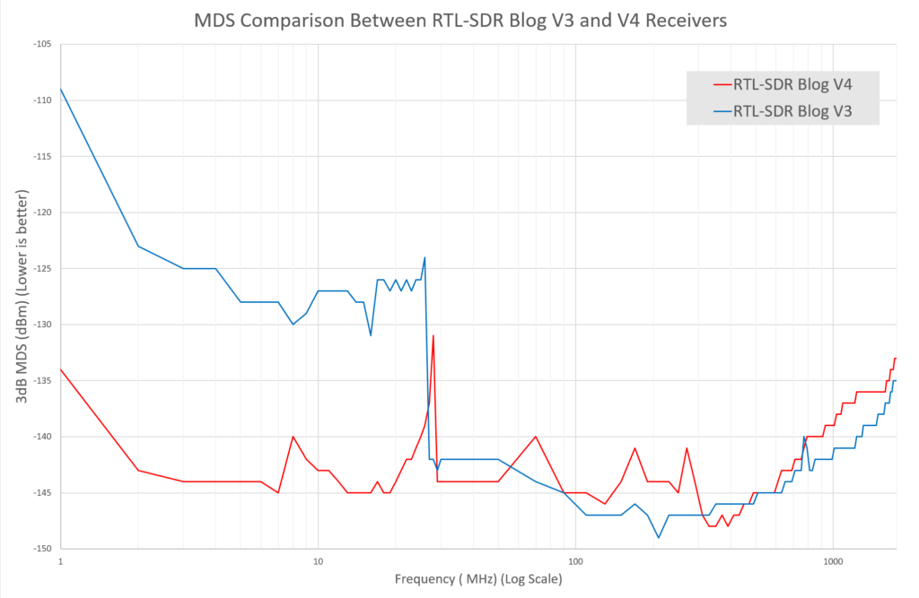
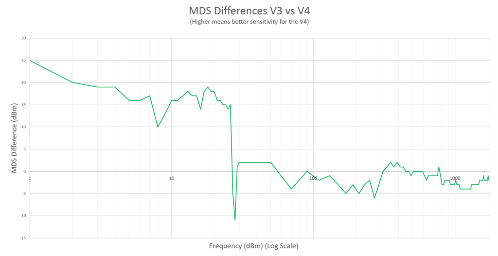
The minimum discernable signal (MDS) is a test we can do to determine what is the minimum power level that a receiver can detect.
The results show that the MDS has significantly improved on the HF bands thanks to the upconverter design. However, there is some minor degradation in the VHF and UHF band.
MDS Measurements (Low values are better)MDS Comparison (Higher means better sensitivity for the V4)
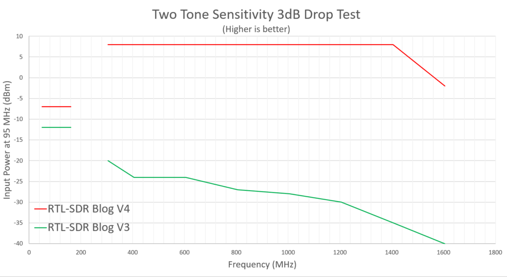
Two Tone Isolation & Desensitization Test
Strong out of band signals can cause an SDR to desensitize on other bands. For example, very strong broadcast FM (which is common), can cause signals being received on other frequencies to be received with a lower signal to noise ratio.
In this test we injected an "interference" tone (Tone A) at 95 MHz, and injected a second tone (Tone B) at another frequency. We then slowly increased the power on Tone A. When we noticed a 3 dB drop in the signal strength of Tone B we recorded the power level of Tone A that this occurred at.
This gives us a way to see the effect of the triplexer filters and notch filters when compared against the Blog V3 which has no filtering. A higher recorded value means that a stronger signal is required to desensitize the receiver, meaning that the strong signal handling capability is improved.
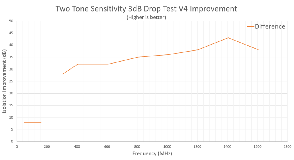
From the difference graph we can see that isolation results within the same triplexer band are improved by about 8 dB thanks to the notch, and then out of band isolation is improved by 28 - 43 dB thanks to a combination of the triplexer filters and notch.
We note that between 305 - 1405 our measurements were limited by the max power out from our signal generator, and we believe the true results are roughly 5dB better than what was recorded at these frequencies.
Two Tone Sensitivity Drop TestIsolation Improvement in the RTL-SDR Blog V4
Should I upgrade if I have an RTL-SDR Blog V3?
If you are happy with the RTL-SDR Blog V3's performance, then there is absolutely no need to upgrade as you will likely see similar performance. However, if you are purchasing a new dongle it may be wise to consider the V4 model as we believe the V4 will be a receiver that is more suitable in many situations.
Thanks
We wanted to extend some thanks to Erlend S. Ervik/LB6MI, Jack T. and everyone over the years who has given some input to RTL-SDR design.
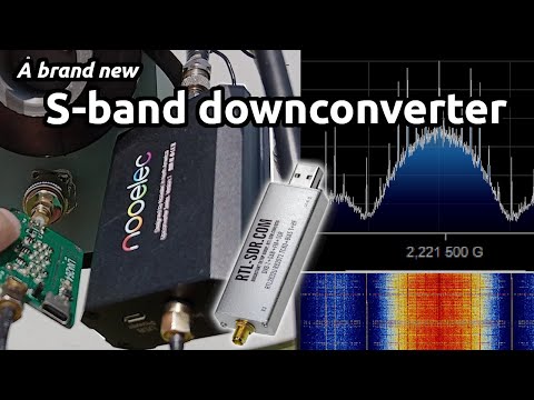
Over on his YouTube channel dereksgc has uploaded a new video where he tests out a new yet to be released downconverter product from NooElec. A downconverter works by shifting high frequencies down into a range that can be received by the RTL-SDR. This makes it useful for receiving 2.2 GHz S-band satellite downlinks which is out of the tuning range of RTL-SDR dongles.
In his video dereksgc shows the new 'Ham-it-down' downconverter, and tests it with an LNA and S-band helix feed and dish. He shows that he is able to easily receive S-band telecommunications satellites without a dish, and with a dish he is able to receive the Coriolis and Chandrayaan-3 satellites.
The ham-it-down is expected to cost US$90 when released. We note that a much lower cost solution might be a commercial 2.2 GHz MMDS downconverter which also comes built in with an LNA and filtering and can be obtained from Aliexpress for less than US$20. Alternatively, the $90 might be better put towards a HackRF clone which is almost the same price and can receive S-band natively without the need for external downconverter.
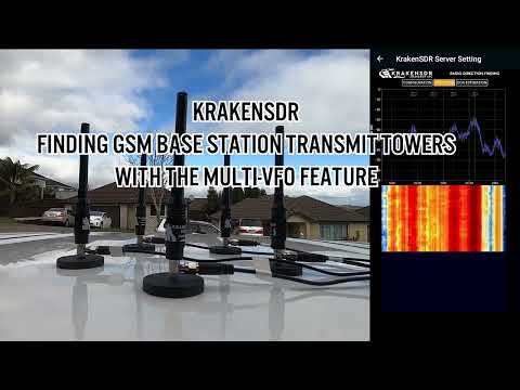
If you weren't already aware, KrakenSDR is our 5-channel coherent radio based on RTL-SDRs, and it can be used for applications like radio direction finding. KrakenSDR is in stock and can be purchased from CrowdSupply or Mouser. More information is also available on our website at krakenrf.com.
Last month we used the KrakenSDR to find the location of a low power FM transmitter. Now in this video we're using KrakenSDR to find the location of GSM base station transmit towers for four frequencies. We're also using the multi-vfo feature to capture the bearing data of these four frequencies simultaneously which can save us some search time.
Once we've found the first transmit tower, we already have some logged bearing data that can be used to help us find the second tower faster. Then the third and fourth towers are even faster to find due to even more data having already been collected.
Interestingly, it also turns out that the first frequency we search for is actually being used by another tower that we pass along the way back. The location of this tower was picked up on the drive back to the first tower. It's possible that these two towers which are a few kilometers apart are covering different areas with directional antennas.
Also note that the first two transmitter searches use the "auto-zoom" map camera feature, which will automatically zoom the screen to show both the vehicle and estimated transmitter location. The second half uses the standard free camera mode.
This is on a new build of the App which is currently in testing, so some things may look slightly different to the currently released version. The new app version will have some minor feature improvements.
KrakenSDR: Finding Multiple GSM Base Station Transmit Towers with the Multi-VFO Feature