Testing the Electrosense Up/Downconverter Expansion Board For 0 – 6 GHz
The Electrosense network is an open source project aiming to deploy radio spectrum sensors worldwide. The idea is to help analyze and understand radio spectrum usage across the globe. Each sensor consists of an RTL-SDR, Raspberry Pi and an optional downconverter to receive the higher bands. If you're interested we wrote an overview of the project in a previous post.
Recently we received a sample of their Up/Downconverter expansion board which is used to expand the frequency range of the RTL-SDR to 0 MHz to 6 GHz. The converter board is entirely open source with the design files available on GitHub. The team note that they are also working on a V2 version which will be cheaper and smaller. The schematic and Firmware for the V2 is also available right now, but it is still under early testing and may change.
The board is not for sale, however you can apply to be considered for a free unit if you want to host your own Electrosense node and meet their criteria. If you do not you can still produce the board yourself. The team mention that the design is easily hand soldered, but there are a few difficult LGA components like the PLL, crystals and mixer which require a heat gun to solder. A the same time they also note that it is possible to get PCB manufacture and SMT assembly done for you for dirt cheap by PCB prototype companies like JLC PCB.
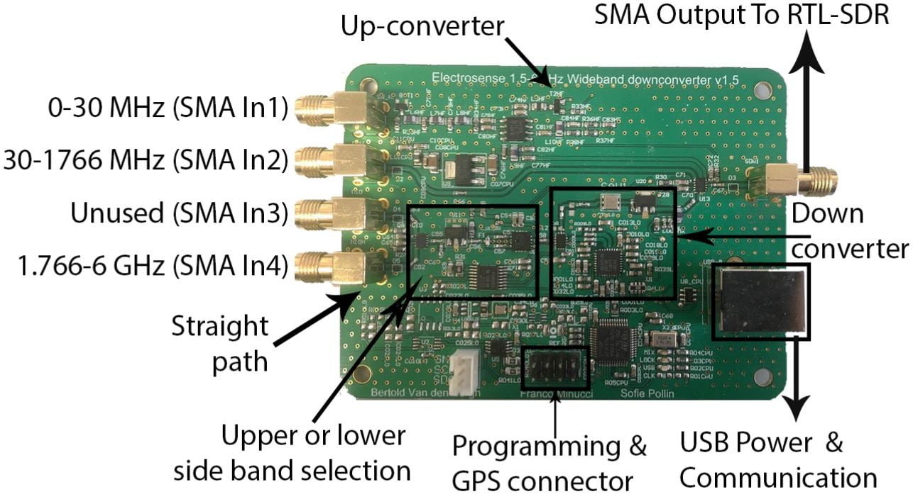
The Expansion Up/Downconverter Board
The converter board has 4-input SMA ports (only 3 are used) and one output port which connects to the RTL-SDR. The first input port is for the HF antenna input. This input connects to the circuit which converts 0 - 30 MHz into a higher frequency which can be received by the RTL-SDR. The second port is simply a pass through for the standard 24 MHz - 1.766 GHz range of a normal SDR. The third port is unused, and the fourth port connects the antenna to the downconverter circuit which allows us to receive from 1.766 GHz to 6 GHz.