Tagged: l-band

Testing a Prototype of the Outernet L-Band Downconverter

Outernet are a startup company that hope to revolutionize the way people in regions with no, poor or censored internet connectivity receive information. Their service is downlink only, and runs on C and L-band satellite signals, beaming up to date news as well as other information like books, educational videos and files daily. To receive it you will need one of their official or homemade versions of the Lighthouse or Lantern receivers (the latter of which is still to be released), or an RTL-SDR or similar SDR. Recently they began test broadcasts of their new 5 kHz 1539.8725 MHz L-band signal on Inmarsat I4F3 located at 98W (covers the Americas), and they hope to begin broadcasts in more regions soon too.

The typical RTL-SDR is known to often have poor or failing performance above 1.5 GHz (though this can be fixed to some extent), so Outernet have been working on an L-band downconverter. A downconverter works by receiving signals, and shifting them down to a lower frequency. This is advantageous because the RTL-SDR is more sensitive and does not fail at lower frequencies, and if used close to the antenna, the lower frequency allows longer runs of cheap coax cable to be used without significant signal loss.

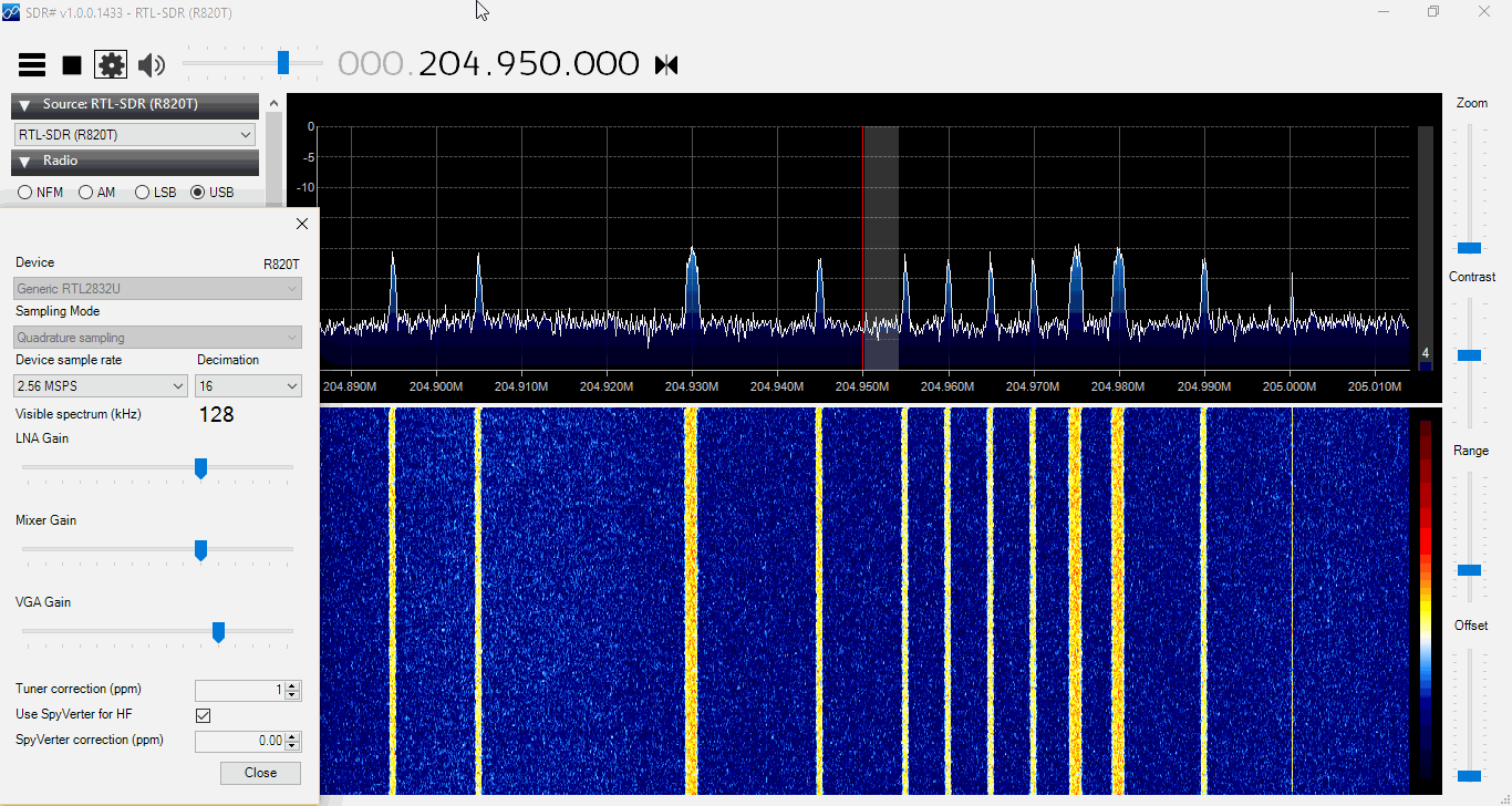
Earlier this week we received in the mail a prototype of their downconverter. The downconverter uses a 1.750 GHz LO signal, so any signal input into it will be subtracted from this frequency. For example the STD-C frequency of 1.541450 GHz will be reduced to 1750 MHz – 1541.450 MHz = 208.55 MHz. This also means that the spectrum will appear reversed, but this can be corrected by selecting “Swap I & Q” in SDR#. The downconverter also amplifies the signal with an LNA, and has a filter to remove interfering out of band signals.

The Outernet downconverter circuit board.
The prototype Outernet downconverter circuit board.
Specsheet for the downconverter.

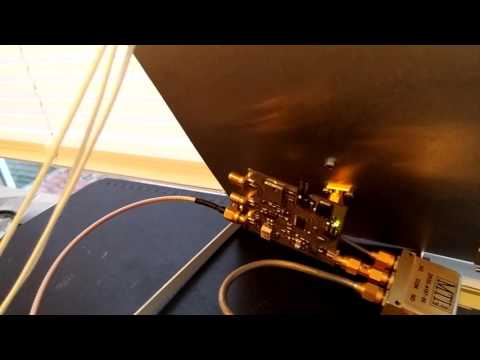
We tested the downconverter using their patch antenna which they had sent to us at an earlier date (the patch antenna is used and shown in this Inmarsat STD-C reception tutorial). Our testing found that overall the downconverter works extremely well, giving us much better signal levels. Previously, we had used the patch + LNA4ALL and were able to get reception good enough to decode STD-C and AERO signals, but with the requirement that the patch be carefully pointed at the satellite for maximum signal. With the downconverter the signals come in much stronger, and accurate pointing of the patch is no longer required to get a signal strong enough to decode STD-C or AERO.

The downconverter can be powered by a bias tee connection, and this works well with our bias tee enabled RTL-SDR dongles. We also tested with the bias tee on the Airspy R2 and Mini and had no problems. It can also be powered with a direct 5V connection to a header, and they note that the header will be replaced by a USB connector in the production version.

The release date and exact price that these will be sold at is not confirmed, but we believe that it will be priced similarly to upconverters at around $50 USD or less. A good low cost downconverter should help RTL-SDR and other SDR users receive not only the Outernet signal better, but also other satellite signals such as STD-C and AERO. Although the input is filtered and the RF frequency is specified at 1525 to 1559 MHz, we had no trouble receiving signals up to GPS frequencies of 1575 MHz, and even up to Iridium signals at 1.626 GHz, though reception was much weaker up that high.

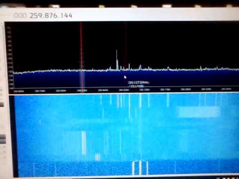
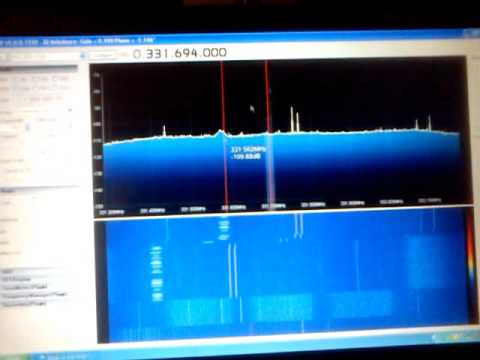
Below are some screenshots of reception. Here we used the Outernet patch antenna sitting in a windowsill with the downconverter directly after the antenna, and then 10 meters of RG6 coax cable to the PC and bias tee enabled RTL-SDR. We found that with the downconverted ~200 MHz signal the loss in the RG6 coax was negligible. Better reception could be obtained by putting the patch outdoors. In some screenshots we used Vasilli’s R820T driver with the decimation feature, which allows you to zoom into narrowband signals much more clearly.

Some AERO Signals Zoomed in with the Decimation feature in SDR#.
Some AERO Signals Zoomed in with the Decimation feature in SDR#. Received with the Outernet downconverter and patch antenna.
Some AERO and other Signals Zoomed in with the Decimation feature in SDR#.
Some AERO and other Signals Zoomed in with the Decimation feature in SDR#. Received with the Outernet downconverter and patch antenna.
Signals zoomed out.
Signals zoomed out. Received with the Outernet downconverter and patch antenna.

Receiving up to 4.5 GHz with an RTL-SDR and a $5 Directv Downconverter

KD0CQ has recently been experimenting with trying to receive signals at frequencies of up to 4.5 GHz with an RTL-SDR and downconverter. Since a typical R820T/2 RTL-SDR’s maximum frequency limit is about 1.7 GHz, an external downconverter circuit is required. A downconverter converts high frequencies down into the range receivable by the RTL-SDR. For example a downconverter with a 2.4 GHz local oscillator would convert a 3.5 GHz signal down to 1.1 GHz, which can be easily received by an RTL-SDR.

The secret to doing this cheaply is revealed by KD0CQ. He shows that a very cheap $5 Directv SUP-2400 upconverter can be converted into a 2.4 GHz downconverter simply by removing some filters. He writes that he hasn’t uploaded the full set of steps to modify the SUP-2400 yet, but he intends to do so in the near future.

There is also a discussion about this mod on Reddit. Several posters have been discussing what applications a cheap downconverter could open up. Some mentioned applications include receiving various satellites in the C/S bands, DECT cordless phones @ 1.9 GHz, SiriusXM satellite radio @ 2.3 GHz, ISM @ 2.4 GHz, RADARs, RC aircraft control/telemetry/video and ham beacons.

The SUP-2400 Directv upconverter that can be converted into a downconverter.
The SUP-2400 Directv upconverter that can be modified into a downconverter.

$5 Microwave Downconverter for the RTLSDR KD0CQ

Comparing LHCP and RHCP Reception of a Thuraya Satellite with an RTL-SDR and MIX4ALL

Over on YouTube Adam Alicajic 9A4QV (creator of the popular LNA4ALL) has uploaded a video showing a comparison of reception of Thuraya satellites with a LHCP (left hand circular polarization) and RHCP (right hand circular polarization) patch antennas. To receive Thuraya satellites, a LHCP antenna should be used, and Adam’s results show that using an antenna with the wrong polarization (RHCP) produces a signal that is as theoretically expected almost 20dB lower. Shortly after initially posting this Adam wrote in to comment on the following:

Thuraya LHCP original patch antenna have 2 patches stacked inside the panel antenna and the hand made RHCP patch antenna is made only of 1 patch. Theoretically, this should give the 3dB more gain for the Thuraya antenna.

The difference in the received signal due to polarization should be (theoretically) 20dB, thats RHCP vs. LHCP and I experience some 18dB of difference which is good result. Why not 20dB? First of all it is impossible to get 3dB more gain stacking the antennas, this is just the theory, more likely 2db in the practice.

To receive the signals Adam uses the patch antennas, which are connected to the MIX4ALL (a downconverter that he is currently developing), which is then connected to a RTL-SDR dongle.

In the first video Adam shows the difference the wrong polarization makes, and in the second he shows some information about the Thuraya LCHP antenna he uses.

Receiving Thuraya sat - LHCP and RHCP comparison using MIX4ALL

Thuraya antenna L-band + GSM

Building a Wideband Helix Antenna for L/S/C Bands

Over on YouTube user Adam Alicajic (creator of the popular LNA4ALL low noise amplifier) has uploaded a video showing the performance of a home made wideband helix antenna that he has created for receiving signals such as ones from L-Band Inmarsat satellites. See our tutorial for more information on receiving Inmarsat signals.

Adams helix antenna is built out of an old used can and is based on a 1.1 turn design. In the first of three videos he shows that the SWR of the antenna is all well below 2.0 from 1.5 GHz to 3 GHz. In the second video Adam shows the performance of the helix antenna on actual L-band signals being received with an RTL-SDR dongle. In the final video Adam compares the helix again a patch antenna and finds that the two receive with very similar performance.

Wideband L/S/C band helix antenna Part.1

Wideband L/S/C band helix antenna Part.2

Wideband L/S/C band helix antenna Part.3

Testing RTL-SDR and SDRPlay receivers for AERO reception

Jonti, the programmer of the JAERO decoder for L-band AERO signals recently bought and received one of our new RTL-SDR Blog dongles and also an SDRplay unit for testing L-band reception. Previously he had been using a standard RTL-SDR dongle. Now he’s done a write up comparing the performance of the three units on L-band AERO reception.

The two most important things to pay attention to when receiving AERO signals are signal SNR and frequency stability. In order to lock on to the signal, the signal’s frequency must remain relatively stable over a short period of time. For the stability test Jonti writes the following, referencing the image posted below:

You can see the old RTL dongle moves almost 3kHz within a couple minutes after being turned on, this speed is so rapid that JAERO can’t keep up with the frequency changed during this period of time. What’s odd is the old RTL dongle does some fairly crazy stuff around 20 minutes in that lasts for about 15 minutes, JAERO also can’t cope with some of that. The other thing to notice in the old RTL’s spectrograph are vertical lines, these lines I believe are caused by interference entering the dongle between the RTL dongle’s tuner and ADC (analog-to-digital converter).

The frequency stability of the new RTL dongle can only be described as amazing!!! There is not much more than 100 Hz change during the whole test.

The range of frequencies for the SDRPlay is similar to that of the old RTL dongle of about 3kHz. The difference being the transition from the lowest frequency to the highest frequency is slow. Any demodulator should not have any issue tracking this slow and steady change. The only problem you will encounter here is when you are trying to tune into a particular frequency your frequencies will be slightly different depending on the temperature of the SDRPlay.

The results of the frequency stability test on an AERO signal. Standard RTL-SDR, RTL-SDR Blog Unit, SDRplay.
The results of the frequency stability test on an AERO signal. Left: Standard RTL-SDR; Middle: RTL-SDR Blog Unit; Right: SDRplay.

Jonti also found that in terms of sensitivity the SDRplay was the best at receiving when a non active antenna (an active antenna is an antenna with a built in LNA) was used. The RTL-SDR dongles could not receive well at all when a non active antenna was used. When an active GPS antenna was used the SDRplay was only about 1dB more sensitive than the RTL-SDR dongles.

In his article Jonti expressed concern that the SDRplay did not see much improvement in SNR over the RTL-SDRs when an active antenna was used. Our thoughts on the sensitivity findings are that the SDRplay does not see much improvement with an active antenna because the noise figure of the system is not reduced any further by adding an additional front end LNA (the noise figure in a RF system is almost entirely determined by the first LNA in a RF chain). Adding an extra LNA could even potentially make reception worse by reducing the overall linearity of the system. An external LNA would only be beneficial if a long run of coax was used between the feed and SDR, and in Jonti’s connections he connected the feed and SDRplay with a very short cable. The RTL-SDR only works well with an active antenna because its raw sensitivity at 1.5 GHz isn’t great, and it needs the extra boost from the LNA.

Testing the SDRplay with a non-active antenna.


Testing the MIX4ALL Downconverter on L-Band

Adam (9a4QV) is well known in the RTL-SDR community for creating and selling the LNA4ALL low noise amplifier and several filter circuits as well. Now Adam has uploaded on his YouTube channel a new video that shows a prototype of his latest upcoming RTL-SDR compatible product called the MIX4ALL. The MIX4ALL is a downconverter that will improve the ability of the RTL-SDR to receive satellite signals in the L-band which are usually at around 1.5 GHz.

It is known that the most common R820T/2 RTL-SDR’s are not very sensitive at 1.5 GHz, and some can even stop receiving properly at this frequency when they get too hot. A downconverter will simply convert the 1.5 GHz signals into a lower frequency which can be received much better by the RTL-SDR.

In the first video Adam shows the MIX4ALL being used with an RTL-SDR to receive various Inmarsat signals with a patch antenna. In the second video he shows reception of AERO-I signals.

Adam writes that he expects to be able to sell the MIX4ALL near the end of January 2016.

MIX4ALL test @ L-band Inmarsat

MIX4ALL AERO-I L band Inmarsat 4F2

RTL-SDR Heat Dissipation as seen by a Thermal Camera

The RTL-SDR is known to get quite hot during operation and when it gets too hot reception of frequencies over 1.2 GHz can be degraded. Marko Cebokli wrote into us at RTL-SDR.com to show us some thermal imaging pictures that he has made of the RTL-SDR PCB. The images clearly show that the hottest part of the PCB is the R820T chip. The RTL2832U chip stays cool and the only other hot component on the PCB is the voltage regulator. In the post Marko also explains his conclusions on why the reception fails at frequencies over 1.2 GHz when it gets too hot.

The images show that the top of the R820T chip reaches a temperature of 85 degrees Celsius after just 10 minutes of operation. The underside of the chip reaches 68.9 degrees Celsius. Marko writes that these temperatures may be even higher when the RTL-SDR is placed inside the plastic case.

In general the RTL-SDR runs fine at these temperatures, but cooling the R820T chip will improve performance when tuning into signals that are higher than 1.2 GHz, for example with L-band satellites. Other RTL-SDR enthusiasts have cooled their RTL-SDR’s with thermal pads, heatsinks, fans and oil.

The RTL-SDR PCB seen with a thermal camera

Another L-Band Antenna Build and comparing L-Band reception on the RTL-SDR, HackRF and SDRplay

Over on Reddit user killmore231 has made a post showing his comparison of L-Band reception with RTL-SDR, HackRF and SDRplay software defined radios. killmore231 built the L-band patch antenna which Adam 9A4QV showed how to build on his YouTube channel late last month.

When testing the antenna on his RTL-SDR he saw no reception of any L-band signals at all. The RTL-SDR requires an external LNA to properly receive signals at this frequency range, which he did not have. Next he tried it on his HackRF and saw that some signals were weakly visible. When he tried it on his SDRplay the L-band satellite signals were clearly visible, probably due to the SDRplay’s good sensitivity at this frequency range and the fact that it has a built in LNA. His results show that the SDRplay is a good SDR for receiving L-band satellites as it does not need an external LNA for decent reception. An external LNA may still be needed if a long run of coax cable is used however.

SDRplay reception of L-band satellite signals with no external LNA.
L-band patch antenna