Tagged: rtl-sdr

Testing a Prototype of the Outernet L-Band Downconverter

Outernet are a startup company that hope to revolutionize the way people in regions with no, poor or censored internet connectivity receive information. Their service is downlink only, and runs on C and L-band satellite signals, beaming up to date news as well as other information like books, educational videos and files daily. To receive it you will need one of their official or homemade versions of the Lighthouse or Lantern receivers (the latter of which is still to be released), or an RTL-SDR or similar SDR. Recently they began test broadcasts of their new 5 kHz 1539.8725 MHz L-band signal on Inmarsat I4F3 located at 98W (covers the Americas), and they hope to begin broadcasts in more regions soon too.

The typical RTL-SDR is known to often have poor or failing performance above 1.5 GHz (though this can be fixed to some extent), so Outernet have been working on an L-band downconverter. A downconverter works by receiving signals, and shifting them down to a lower frequency. This is advantageous because the RTL-SDR is more sensitive and does not fail at lower frequencies, and if used close to the antenna, the lower frequency allows longer runs of cheap coax cable to be used without significant signal loss.

Earlier this week we received in the mail a prototype of their downconverter. The downconverter uses a 1.750 GHz LO signal, so any signal input into it will be subtracted from this frequency. For example the STD-C frequency of 1.541450 GHz will be reduced to 1750 MHz – 1541.450 MHz = 208.55 MHz. This also means that the spectrum will appear reversed, but this can be corrected by selecting “Swap I & Q” in SDR#. The downconverter also amplifies the signal with an LNA, and has a filter to remove interfering out of band signals.

The Outernet downconverter circuit board.
The prototype Outernet downconverter circuit board.
Specsheet for the downconverter.

We tested the downconverter using their patch antenna which they had sent to us at an earlier date (the patch antenna is used and shown in this Inmarsat STD-C reception tutorial). Our testing found that overall the downconverter works extremely well, giving us much better signal levels. Previously, we had used the patch + LNA4ALL and were able to get reception good enough to decode STD-C and AERO signals, but with the requirement that the patch be carefully pointed at the satellite for maximum signal. With the downconverter the signals come in much stronger, and accurate pointing of the patch is no longer required to get a signal strong enough to decode STD-C or AERO.

The downconverter can be powered by a bias tee connection, and this works well with our bias tee enabled RTL-SDR dongles. We also tested with the bias tee on the Airspy R2 and Mini and had no problems. It can also be powered with a direct 5V connection to a header, and they note that the header will be replaced by a USB connector in the production version.

The release date and exact price that these will be sold at is not confirmed, but we believe that it will be priced similarly to upconverters at around $50 USD or less. A good low cost downconverter should help RTL-SDR and other SDR users receive not only the Outernet signal better, but also other satellite signals such as STD-C and AERO. Although the input is filtered and the RF frequency is specified at 1525 to 1559 MHz, we had no trouble receiving signals up to GPS frequencies of 1575 MHz, and even up to Iridium signals at 1.626 GHz, though reception was much weaker up that high.

Below are some screenshots of reception. Here we used the Outernet patch antenna sitting in a windowsill with the downconverter directly after the antenna, and then 10 meters of RG6 coax cable to the PC and bias tee enabled RTL-SDR. We found that with the downconverted ~200 MHz signal the loss in the RG6 coax was negligible. Better reception could be obtained by putting the patch outdoors. In some screenshots we used Vasilli’s R820T driver with the decimation feature, which allows you to zoom into narrowband signals much more clearly.

Some AERO Signals Zoomed in with the Decimation feature in SDR#.
Some AERO Signals Zoomed in with the Decimation feature in SDR#. Received with the Outernet downconverter and patch antenna.
Some AERO and other Signals Zoomed in with the Decimation feature in SDR#.
Some AERO and other Signals Zoomed in with the Decimation feature in SDR#. Received with the Outernet downconverter and patch antenna.
Signals zoomed out.
Signals zoomed out. Received with the Outernet downconverter and patch antenna.

Comparing Home Made Inmarsat Antennas

Over on his blog “coolsdrstuff”, the author has uploaded a new post showing his comparisons of various home made Inmarsat antennas. In his post he tests a tin can helix antenna, a 10-turn helix antenna, and a LHCP helix feed on a 81cm DirecTV dish.

His results show that the dish outperforms the helix antennas by a significant amount, but only once he took it outdoors. The 10-turn helix antenna also worked better than the tin can helix, although he found that it required very accurate pointing.

Inmarsat are geostaionary satellites that transmit signals on L-band at around 1.5 GHz. They transmit signals that can be decoded with an RTL-SDR, such as STD-C EGC (weather, messaging and safety messages for boats), as well as AERO (the satellite version of ACARS for aircraft).

Good Inmarsat reception with the dish.

Multi-RTL: A GNU Radio Block for Combining and Time Synchronizing Multiple RTL-SDR Dongles

The RTL-SDR has a maximum available stable bandwidth of about 2.4 MHz. Many people have had the idea to combine multiple RTL-SDR dongles together to implement a wider band or multi channel RX device, but very few successful implementations have been seen. The biggest challenge is time synchronization between the multiple RTL-SDR units. Even if a common clock is used, there is no guarantee that the samples streams are synchronized, which can cause problems for the decoding of many signals. The most successful implementations so far have used a common clock, and an external synchronization signal from a generator in addition to other hardware like switches.

However, now Piotr Krysik has come up with a very good and simpler solution for the synchronization of RTL-SDR dongles. Piotr wanted to be able to capture both GSM uplink and downlink channels at the same time. As these channels are not close to each other in the frequency spectrum, he needed two synchronized RTL-SDR dongles to be able to monitor the two channels at once. In order to achieve synchronization he created a GNU Radio block called Multi-RTL, and connected two RTL-SDR dongles to a common clock source.

In his Multi-RTL block he implemented a method of a discovery he made that allows a way to time synchronize the dongles by using a signal that is already being broadcast over the air. He writes that his method is the following:

  • tuning the RTL-SDR dongles to the same frequency where some transmission is present,
  • recording a short signals with all of the dongles,
  • computing cross-correlation of the signals (i.e. with respect to a one selected channel),
  • finding position of maximums of cross-correlations in order to estimate relative delays of the channels,
  • correcting the delays so the channels are time-synchronized,
  • switching the dongles to their target frequencies,
  • changing other parameters of the channels (like gains) to target values.

With his Multi-RTL GNU Radio block Piotr was able to successfully monitor a GSM uplink and downlink channel pair that were spaced 45 MHz apart. Whilst monitoring the signals he sent an SMS to his phone, and then using his recovered encryption key was able to use gr-gsm to decode his message.

The successful implementation of this tool opens the door for many more RTL-SDR based projects, such as the reception of GSM uplink and downlink channels simultaneously, reception of frequency hopping signals, passive radar, and the receiving and decoding of signals with a bandwidth wider than 2.4 MHz.

Two dongles with a common clock.
Synchronizing two dongles by using an external signal.

Sniffing Data from an Implanted Heart Defibrillator

Over on Hackaday a team are attempting to reverse engineer the RF data logging portion of an implanted cardiac defibrillator (ICD) as their Hackaday prize entry. An ICD defibrillator works by monitoring heart condition and automatically applying gentle shocks to put the heart back into a stable rhythm if an abnormal rhythm is detected. Modern implanted defibrillators log heart data and transmit the log daily to a base station, which is then forwarded to the doctor for analysis.

Unfortunately patients who are interested in taking a more active approach to their health (such as one member of the team who herself has an implanted defibrillator) do not get to see this data. The team are hoping to use an RTL-SDR to sniff this data which is transmitted in the 402 – 405 MHz ISM band, and then implement a decoder. So far they have successfully been able to capture some signals, and are working on decoding them into data.

By reverse engineering the signal they hope to draw attention to the fact that healthcare providers are not providing real time body data to the patient, preventing them from making their own informed decisions about their health. They write:

It’s all about making informed decisions. A patient knowing about arrhytmias episodes that occured to him/her has the power to change his lifestyle accordingly, by deducing the factors that have influenced his recent attacks and eliminating them – i.e. observing his/her heart condition according to his/her sleep schedule, work rhythm, food choices and participation in sports. As for now, the patients can only hope to get some information on ICD-prevented arrhytmias on scheduled appointments with their doctor, which often occur once a year or even less often. This eliminates any possibility of making informed choices by using patient’s lifestyle data for future arrhythmia episode prevention.

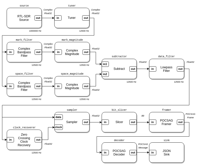
The planned reception and decoding flowgraph.

Decoding the NOAA Weather Satellite Telemetry Beacons

It is well known that the NOAA satellites broadcast weather satellite images which can be received and displayed with an RTL-SDR and computer. What is less known is that there is a telemetry beacon that is also transmitted by the same satellites. The telemetry not only contains data such as the current spacecraft time, day and ID, but also contains scientific data from on board instruments such as:

  • The HIRS/3 and HIRS/4 instruments which is a high resolution infrared sounder which can be used to create a low resolution multi-spectral scan of the earth. (more info)
  • The Space Environment Monitor (SEM-2) which has a Medium Energy Proton and Electron Detector (MEPED), and a Total Energy Detector (TED). This experiment is used to measure the effect of the sun on satellite communications. (more info)
  • The experimental DCS/2 transmitter which retransmits signals from 401.65 MHz sea buoys, arctic fox collars, sea ice monitors, weather balloons and more. (more info pdf)
  • The ARGOS Advanced Data Collection System (ADCS) which amongst other uses is used in research for tracking animal GPS collars around the world.

On GitHub user nebarnix has been working on a standalone C based decoder for these NOAA satellite telemetry beacons. So far from her wiki log, it appears that she has been able to get HIRS decoding and producing an image, receive and graph SEM-2 data, and decode the locations of some fixed DCS transmitters.

A HIRS multispectrum scan of the earth from the NOAA-18 satellite telemetry beacon.

Building a very low cost satellite tracker for your RTL-SDR

A satellite tracker is a motorized unit that points a directional antenna towards passing satellites. Most satellites are not in a fixed orbit, and will fly over your head a few times a day and will be receivable for a few minutes, and a directional antenna is usually recommended since the signals can be weak. The goal of the SatNOGS project is to set up various volunteer satellite tracker stations around the world, and network the received data on the internet, so that satellite data is always being received and shared.

Over on his blog, Paul has written up a tutorial showing how he’s managed to make a super cheap satellite tracker for his RTL-SDR using some pan/tilt servos, a Yagi antenna made from measuring tape, and and Arduino running the SatNOGS tracking software. When he tested the tracker he was able to receive NOAA 18 and some of the XW-2 satellites.

Although the tracker works, he admits that there are some problems and that it is probably not as good as the SatNOGS recommended build, which is a more permanent solution. But the SatNOGS build requires access to a 3D printer and higher quality components, so Paul’s solution is a much cheaper solution to implement at least for experimentation.

The low cost satellite tracker built by Paul.

Satellite Tracker NOAA 18 40x

Demonstrating the IF Processor and Notch Filter Plugin in SDR#

Over on YouTube user  FMDX HUN (Luc1f3rk0) has uploaded a video showing how useful the SDR# IF Processor and Notch Filter Plugin can be when attempting to DX FM broadcast stations. He shows that it can be used to listen to stations that are almost overlapping by cutting out the unwanted signal.

The plugin itself can be downloaded from http://rtl-sdr.ru/page/para-novyh-plaginov.

SDRSharp+IF Processor & Tracking Notch Filter Plugin demostration

QSpectrumAnalyzer Updated to Version 1.4.0

QSpectrumAnalyzer is a Linux based opensource GUI front end for rtl_power or rtl_power_fftw and can be used with an RTL-SDR to scan for signal activity on wide swaths of the frequency spectrum. Recently QSpectrumAnalyzer was updated to version 1.4.0 and the new updates add the following features:

  • Max peak hold
  • Min peak hold
  • Averaging
  • Spectrum Persistence (RTSA fosphor-like effect)
  • Smoothing

Previously we posted about QSpectrumAnalyzers ability to use rtl_power_fftw, which is a much faster version of rtl_power. The new features help make the spectrum view clearer especially when using rtl_power_fftw at a very short interval.

qspectrumanalyzer_screenshot qspectrumanalyzer_screenshot2