Category: Airspy

Creating a 21cm Galactic Sky Map with an Airspy and 1.8m Dish

Marcus Leech from ccera.ca is a pioneer in using low cost software defined radios for observing the sky with amateur radio telescopes.  In the past he's shown us how to receive things like the hydrogen line,  detect meteors and observe solar transits using an RTL-SDR. He's also given a good overview and introduction to amateur radio astronomy in this slide show.

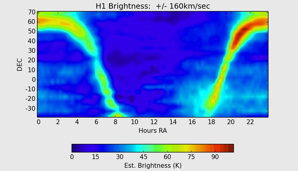
His recent project has managed to create a full Hydrogen sky map of the northern Canadian sky. In his project memo PDF document Marcus explains what a sky map shows:

A [sky map] shows the brightness distribution over the sky for a given set of observing wavelengths. In the case of the 21cm hydrogen line wavelength, maps show the distribution of hydrogen over the sky. For amateur observers, such maps generally show the distribution within our own galaxy, since extra-galactic hydrogen is considerably more faint, and significantly red/blue shifted relative to the rest frequency of 1420.40575 MHz, due to relative motion between the observer and the target extra-galactic hydrogen.

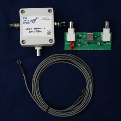
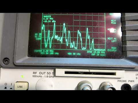
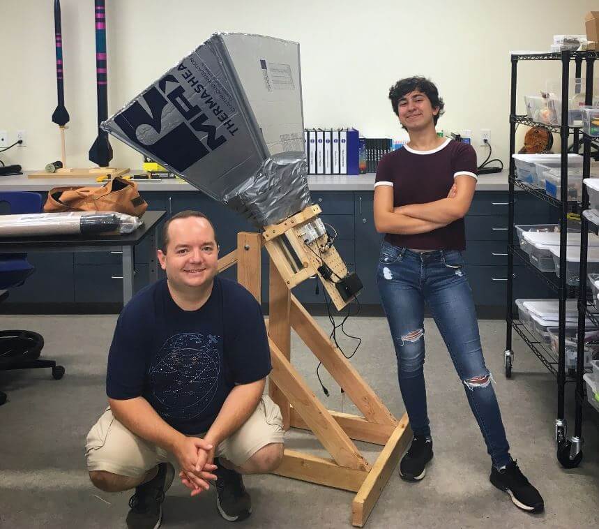
He was able to make this observation using his radio telescope made from a 1.8m dish antenna, a NooElec 1420 MHz SAWBird LNA + Filter, a 15dB line amplifier, another filter and two Airspy R2 software defined radios locked to an external GPSDO. The system runs his custom odroid_ra software on an Odroid XU4 single board computer, which provides spectral data to an x86 host PC over an Ethernet connection. 

Over 5 months of observations have resulted in the Hydrogen sky map shown at the end of this post. Be sure to check out his project memo PDF file for more information on the project and how the image was produced. Marcus' blog post over on ccera.ca also notes that more data and different maps will be produced soon too.

Hydrogen Sky Map
Hydrogen Sky Map

An Active Low Cost HF Loop Antenna Made in the UK

Cross Country Wireless is a UK based company that has created an active HF loop antenna for only $70 USD including international shipping. The loop appears to have already been for sale for a while now, but recently they've created a new version that can be easily powered by a 5V bias tee with at least a 67 mA current capacity. This makes it very easy to use with radios that have built in bias tee's such as our RTL-SDR Blog V3 and SDRplay and Airspy units. The page reads:

The Loop Antenna Amplifier contains all the electronics needed for home DIY construction of an active loop (magnetic loop) low noise receiving antenna.

The amplifier consists of two units, a weatherproofed outdoor unit for connection to a suitable loop and a base unit to further amplify the signal and to provide DC power up the coaxial cable to the outdoor unit.

The outdoor unit is housed in a polycarbonate box with stainless steel antenna connections and a BNC socket. The indoor unit is a PCB with two BNC connectors and a USB socket to take 5V from a USB socket on a PC or phone charger.

Like our other active antenna products it has RF overload protection to allow it to be used very close to transmit antennas without damaging the amplifier or the attached receiver.

The loop depends on what the user has available. We have tested it with simple wire loops or deltas, coax loops and an alloy loop made from a bicycle wheel rim. We supply a 3m (10 ft) length of wire as a simple loop to make a first loop for testing.

The photograph on the right shows the prototype with a 1m diameter loop of LDF4-50 coax cable as a test loop.

With a simple wire loop or delta and a small USB powerbank it makes a very compact and portable receiving antenna for holiday listening or covert use.

The latest version can now have the head unit powered directly from receivers with a 5V bias-tee such as the SDRplay receivers or some RTL-SDR dongle receivers with a bias-tee option.

Specifications:

  • Frequency range: 10 kHz to 30 MHz
  • Loop amplifier input impedance: 0.3 ohms
  • Output impedance: 50 ohms
  • Supply voltage: 5 V from USB socket or charger
  • Supply current (head and base unit): 112 mA
  • Supply current (head unit fed with 5V bias-tee): 67 mA
  • Loop antenna outdoor unit connectors: Two M6 stainless steel threaded studs and BNC female (RF out 50 ohms)

There is no comparison yet that we've seen on how this loop compares against the cheaper US$45 Chinese made MLA-30 loop. In a previous post Martin (G8JNJ) reviewed the MLA-30 and noted several design flaws after reverse engineering the circuit. He has let us know that he will also be reviewing the Cross Country Wireless Active Loop and will let us know his thoughts in the future.

Cross Country Wireless Loop
Cross Country Wireless Loop Antenna Amplifier VLF test with 1m diameter coax loop

SDR# 1717 Officially Released: Dark Mode and Other Skins now Available

Release 1717 of the popular SDR# software that is commonly used with RTL-SDR dongles has just officially been released (actually already up to r1722 at the time of this post). This release brings with it UI theme customization including a very nice looking dark mode. Over on the Airspy/SDR# groups.io board programmer Youssef wrote:

We are pleased to announce the release of SDR# r1717 with the Telerik User Interface.

This is quite a big jump from the old UI components that will allow us to add many fancy features in the upcoming revisions.
For now, the functionality of the software was ported "one to one" with full support of the existing plugins.
A new Plugin API for the tool bar was added which allows plugin developers to add/remove special buttons for quick access.

Despite a slightly longer loading time at the startup of the application, many performance improvements should be noticed in run time, especially the CPU usage.
The package is now distributed with a set of skins/themes you can select in the control panel under "Display". Later on, we will add custom skins loading capability so you can customize the look and feel of the whole program.

Please note that some themes have slower rendering than others. You will have to experiment until you settle with something that is acceptable for the eye candy and the CPU usage / UI reactivity.

Some older plugins may not support the "Dark" themes and will have some rendering problems. The last unskinned version of SDR# will be still available for download in case you really need it. In any case, plugin developers are invited to support the new skins by either using Telerik UI components or at least setting the display properties of the old components so they render properly.

SDRSharp Dark Theme
SDRSharp Dark Theme

Leif Continues his Comparisons of the Airspy HF+ Discovery, RSP1, Perseus and more SDRs (Parts 3,4,5)

Leif (sm5bsz)'s series comparing the Airspy HF+ Discovery against various other SDRs such as the Perseus, SDRplay RSP1, Airpsy HF+ Dual, Airspy + SpyVerter and AFEDRI SDR-Net continues again, with parts 3, 4, and 5 now having been uploaded to YouTube. In previous posts we covered parts 1 and 2.

The comparisons are very technically inclined, so may be difficult to follow for those unfamiliar with radio theory. We have highlighted the time stamps where he discusses the results.

In conclusion, for all tests the Perseus always comes out on top, with the HF+ Discovery coming a close second. Generally third best is the HF+ Dual, then the AFEDRI, followed by the Airspy+SpyVerter and RSP1.

Part 3: Here performance with real antenna signals is compared. Attenuators are used to make the noise figure 26 dB of all radios at the output of the 7 port resistive splitter. This video is for dynamic range on 7.2 MHz.

Results @ 30:20

Part 4: Here performance with real antenna signals is compared. Attenuators are used to make the noise figure 27 dB of all radios at the output of the 7 port resistive splitter. This video is for dynamic range on 14 MHz.

Results @ 16:04

Part 5: Here here second order intermodulation is studied.

Results @ 13:07

Building An Open Source SDR Based Hydrogen Line Radio Telescope

Over on Reddit we've seen a post by u/ArtichokeHeartAttack who has been working on a hydrogen line radio telescope, based on an RTL-SDR dongle and horn antenna designs by the DSPIRA program, and the Open Source Radio Telescopes website (site appears to be down, linked to the archive.org copy). [u/ArtichokeHeartAttack] has documented their radio telescope building journey, providing a comprehensive top-level document that is able to point interested people in the right direction towards understanding and building their own Hydrogen line radio telescope.

Briefly, their build consists of a horn antenna and reflector designed for the 1,420.4 MHz Hydrogen line frequency. The horn is built out of a few pieces of lumbar, metallic house wall insulation sheets and aluminum tape. The feed is made from a tin can and piece of wire. In terms of radio hardware, they used an Airspy SDR, GPIO labs Hydrogen Line Filter + LNA, and 2x Uputronics Wide band preamps, and a Minicircuits VBF-1445+ filter. For software processing, they used a GNU Radio flowgraph to integrate and record the spectrum.

The results show that they were able to achieve a good hydrogen line peak detection, and they were able to measure the galactic rotation curve doppler shift, and tangent points which prove that we do in fact live in a spiral galaxy.

The Finished Hydrogen Line SDR Based Horn Radio Telescope Antenna

Leif Continues his Comparisons of the Airspy HF+ Discovery, RSP1, Perseus and More SDRs

Leif (SM5BSZ) is fairly well known in the SDR community for doing very indepth technical tests of various SDR receivers over on his YouTube channel. Recently he's released part two of a series where he compares the new Airspy HF+ Discovery against various other SDRs such as the Perseus, SDRplay RSP1, Airpsy HF+ Dual, Airspy + SpyVerter and AFEDRI SDR-Net. In the first video he studied the blocking and second order intermodulation effects of each SDR using signal generators. We summarized those results in this previous post.

In the new video Leif compares the dynamic range of each SDR using real HF antenna signals at 7.2 MHz. In order to create a fair test of dynamic range, appropriate attenuation is added to each receiver in order to make their noise figures equivalent, so that the incoming signal strength is the same for each SDR.

The first set of dynamic range results is summarized at time 08:14, and these results show the dynamic range comparisons for strong night time signals. Again like in the other videos the Perseus is used as the reference SDR since it is always the best. The tests show that the HF+ Discovery trails behind the Perseus by only -3dB, followed by the HF+ Dual at -10dB, AFEDRI at -15dB, Airspy+SpyVerter at -18dB and finally the RSP1 at -23dB.

The second set of results is summarized at 17:47 and this includes a day time dynamic range test. The rankings are very similar to the night time test.

Hacking Iridium Satellites With Iridium Toolkit

Over on YouTube TechMinds has uploaded a video showing how to use the Iridium Toolkit software to receive data and audio from Iridium satellites with an Airspy. Iridium is a global satellite service that provides various services such as global paging, satellite phones, tracking and fleet management services, as well as services for emergency, aircraft, maritime and covert operations too. It consists of multiple low earth orbit satellites where there is at least one visible in the sky at any point in time, at most locations on the Earth.

The frequencies used by the older generation Iridium satellites are in the L-band, and the data is completely unencrypted. That allows anyone with an RTL-SDR or other SDR radio to decode the data with the open source Iridium Toolkit. If you're interested in how Iridium Toolkit was developed, see this previous post about Stefan "Sec" Zehl and Schneider's 2016 talk.

In the video Tech Minds shows decoding of various data, including an audio call and the satellite tracks and heat map of Iridium satellites.

Hacking Iridium Satellites With Iridium Toolkit

Testing for Spurious Signals on the Airspy HF+ Discovery

Thank you to Nils Schiffhauer (DK8OK) for submitting an article documenting his tests on the Airspy HF+ Discovery (pdf mirror). Spurred on by discussions on the SDR-Console mailing list, Nils went looking for issues with spurious signals generated by the HF+ itself. In the end he finds some minor spurious signals, but notes that they have absolutely no adverse effects once an antenna is connected.

Youssef Touil (developer of the Airspy HF+ line of products) has also noted that the minimum discernible signal (MDS) of the HF+ is so low that it's become normal for very weak spurs to now be visible without an antenna connected. However, once an antenna is connected the natural atmospheric noise floor which is much higher than the MDS hides these spurs, and so the spurs have no consequence on reception.

In Nils' first test he uses a very high end Winradio W65DDC SDR to detect the spurs coming from an Airspy HF+, Airspy HF+ with preselector retrofit, and the Airspy HF+ Discovery. The results are quoted below:

[With the Airspy HF+] you indeed see a very few spurious signals, all well below -140 dBm/Hz.

With the Airspy HF+ Preselector connected, the number of spurious signal is very much reduced, as is their maximum level.

This picture still further improves with the Airspy HF+ Discovery connected: all visible seven spurious signals are measured to well below -150 dBm/Hz.

The first result is clear:

  • Airspy has improved also the spurious signals from model to model, landing at a stunning
    reduction with their matchbox-like Discovery.
  • The spurious signals were significantly reduced in both numbers and level.
  • Together with sensitivity and dynamic range, the performance of these SDRs is exceptionally
    good. If you see their price tag, they are a real bargain.
  • Overall: they deliver professional performance in every important aspect at an incredible low
    price.

In the second test Nils tunes to the center of a spur, then tested with a dummy load and then antenna connected. His results showed that all spurs disappeared once an antenna was connected. He summarizes below:

Yes, there are a very few and low-level spurious signals at all Airspy’s receivers – as they are found [much] worse at some competing SDRs.

  • By development, even this has been significantly improved from model to model with the new Discovery leading the gang.
  • All spurious signals disappear with an antenna connected.
  • There has been found no case where, in practice, any spurious signal even remotely touched or even limited reception of the most miniscule signals.To complain about “spurious signals” simply is “Much Ado about Nothing” in an Ivory Tower, far away from any practical application.
Nils also tested 7300 kHz reception and the co-existance of weak amateur radio signals with strong broadcast signals.