Precisely Synchronizing Multiple HackRFs
Recently Marco Bartolucci & José A. del Peral-Rosado wrote in and wanted to let us know about their work in creating multiple precisely synchronized HackRF’s. They plan to use the synchronized HackRFs for solving at a low cost some interesting navigation problems which are described in detail in their academic paper (IEEE link). The abstract of the paper reads:
This paper describes a new method for the synchronisation of multiple low-cost open source software-defined radios (SDR). This solution enables the use of low-cost SDRs in interesting navigation applications, such as hybrid positioning algorithms, interference localisation, and cooperative positioning among others. Time synchronisation is achieved thanks to a time pulse that can be generated either by one of the SDRs or by an external source, such as a GNSS receiver providing 1PPS signal. Experimental results show that the proposed method effectively reduces the synchronisation offset between multiple SDRs, to less than one sampling period.
In simple terms, hybrid positioning is the process of using multiple signals such as WiFi, Bluetooth and cell phone signals etc together to get an accurate position of the receiver. By using several sources localization accuracy can be improved, but to do this each receiver much be precisely synchronized to the same clock source.
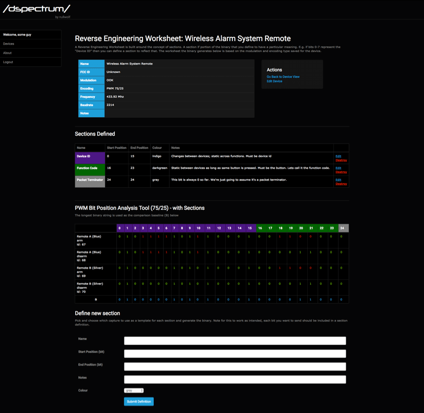
The system they created uses a 1PPS GNSS based time source connected to the SYNC_IN inputs on both HackRFs. The synchronization code is run in hardware on the HackRF’s onboard CPLD (complex programmable logic device). Furthermore they also write the following regarding the system and code which has been adopted into the HackRF repository:
A new time synchronization feature has been recently adopted in the HackRF official repository thanks to the collaboration between SPCOMNAV group, Università di Bologna, and the European Space Agency (ESA).
This contribution allows any user to precisely synchronize multiple HackRF devices below 50 ns, by means of a minor hardware modification and the firmware update.
More information about the driver updates and instructions for use can be found in this Git pull request. The team also write that their work was presented at the NAVITEC 2016 conference.