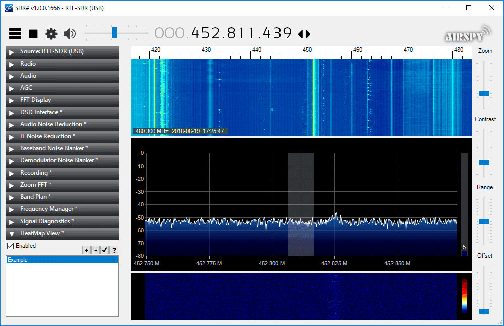
Thanks to VE3NEA for letting us know about his new RTL-SDR compatible heatmap generator plugin for SDR#. To use the plugin you first need to generate some heatmap CSV data by using the rtl_power software. You can then open the CSV file in the plugin and it will generate a heatmap image. A frequency heatmap shows a wideband waterfall image of detected frequency activity.
RTL-SDR heatmap tools are nothing new, but the convenience of having it as a SDR# plugin is that you can click on the heatmap image to instantly tune to a frequency where activity was recorded during the initial rtl_power scan.
The Dreamcatcher v3.0 is Outernet's latest revision of their satellite receiver hardware. The freely available Outernet ku-band satellite service aims to keep us up to date with the latest news, provide books, videos, a daily selection of Wikipedia articles and satellite radio. Compared to the internet, Outernet is download only, and is received via their Dreamcatcher 3 hardware with an an antenna pointed to a satellite. At the moment their Ku-band service is in beta testing and so is only available in the continental United States, but they hope to eventually expand to cover more areas of the world.
Starting from today Outernet are holding a 33% off sale. This means that their Dreamcatcher 3 is only US$99 each. To get the discount use the coupon "33%OFFJULY4SALE" on their store. The sale lasts until Midnight Central Time on Wednesday 4 July. The code is valid site wide, so applies to the moRFeus product as well.
Previous Dreamcatcher implementations utilized an RTL-SDR to receive their L-Band network, however that network has now been discontinued. Dreamcatcher 3 utilizes a hardware based LoRa radio to receive their new ku-band satellite LoRa data stream. However, Dreamcatcher 3 has alternative applications, and doesn't need to be used only for the Outernet data service. Dreamcatcher 3.0 is a full LoRa radio that can transmit and receive, and in this post we'll focus on testing that out.
LoRa is a popular wireless protocol that has been designed for Internet of Things (IoT) devices. It is robust against interference and can be used in low power devices.
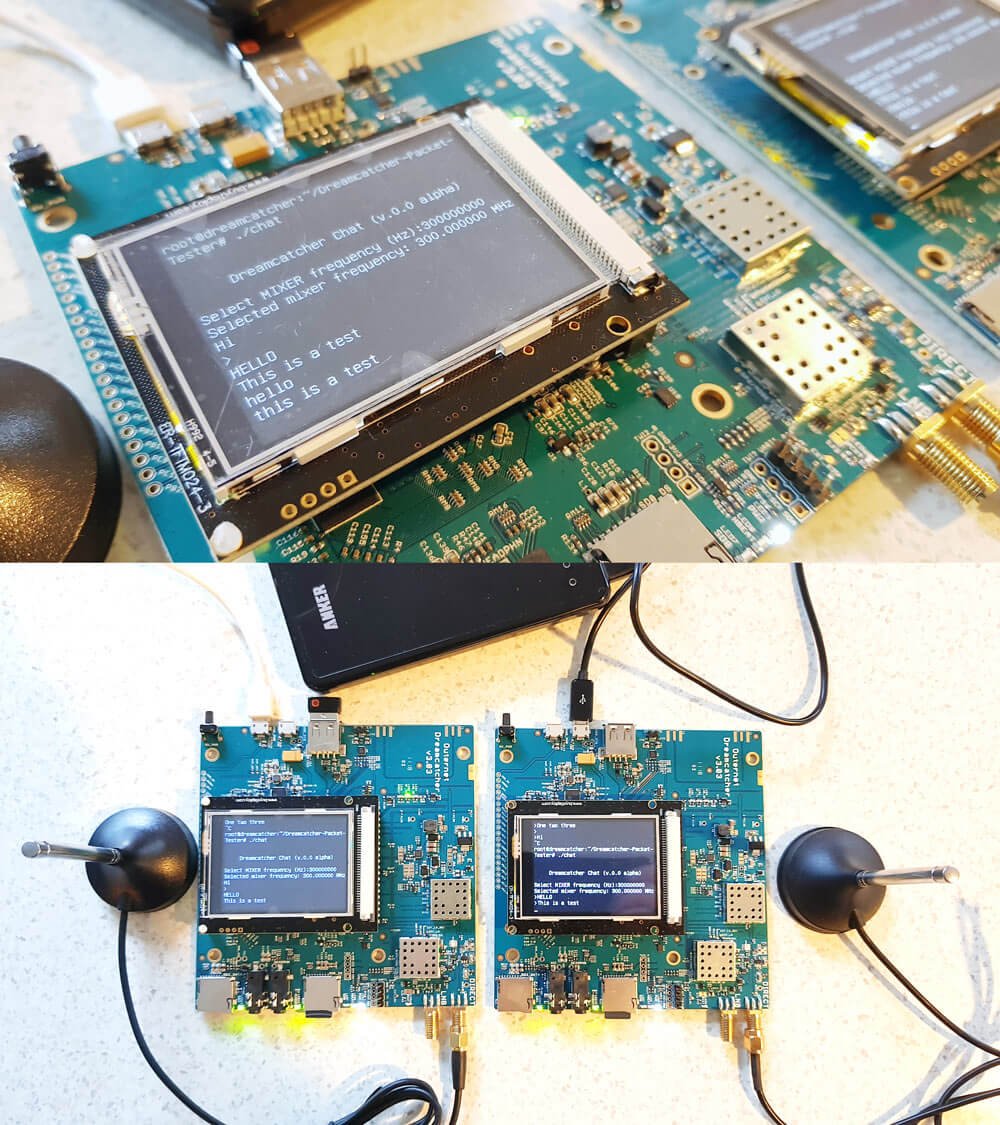
Dreamcatcher 3 LoRa Chat
Outernet have provided a LoRa two way open source text chat application that runs on the Dreamcatcher 3. To use it you'll need two Dreamcatcher 3 boards. With the application you'll be able to chat with short text messages in real time between the boards. Amateur radio enthusiasts may be interested in the boards as an easy way to set up LoRa experiments.
We note that Outernet are not advertising the transmit features specifically as the board is not FCC approved as an intentional radiator, so it cannot legally be used as an ISM band LoRa device for transmitting and listening to LoRa IoT sensors. But as a ham you are able to transmit with it if you can ensure that the output is clean and legal and on the ham bands.
Dreamcatcher 3.0 Running the LoRa Chat App
A brief demo of the chat running below is shown. In the video we're using the default 'spreading factor' setting which results in robust communications, but results in a latency of about 2 seconds. Later we'll show how to change the spreading factor to reduce latency.
The Dreamcatcher v3.0
Outernet kindly provided us with two Dreamcatcher 3 boards to test the chat application with.
Like the previous versions, the Dreamcatcher is a full computing board with radio built into it. Except this time instead of an RTL-SDR, the radio is a hardware LoRa module. Another difference is that now there is a built in LCD screen.
On the board there are two SMA ports, one labelled "Direct" and the other labelled "LNB". The direct port is what we'll need to use for the chat application as this is the port that can transmit. There are also two SD Card slots, one for the OS and one for storage, a microphone and headphone jack, a USB-A slot with a supplied WiFi adapter, and two USB micro slots, one for USB OTG and one for power.
The package also comes with an LNB that is designed to be used with the Outernet satellite service. The LNB is receive only, so cannot be used with the chat application, so you'll need to use your own antenna if experimenting with the LoRa transmitter.
Chat Setup and Usage
First we burnt the latest version of Dreamcatcher Armbian OS to two SD cards and inserted one into each board. Since Dreamcatcher 3 has a built in LCD screen, you can login and access the terminal through the screen. But as there is only one USB port available, you'll need a USB hub to be able to plug in a mouse and keyboard, and the included USB WiFi adapter. Alternatively, if you connect the USB OTG port to a PC, you can connect to it via a USB serial connection. Instructions for connecting via serial, and for setting up a WiFi connection are the same as in our previous Dreamcatcher 2.0 tutorial.
Upon running the program you'll be asked to enter a MIXER frequency. This frequency doesn't really seem to matter and we're not sure why we're asked for it. But you can enter any frequency such as 300000000 Hz (300 MHz).
Once you've opened the chat program on both Dreamcatchers you should be able to type in text on the console, and have it show up on the other Dreamcatcher after pressing enter. Remember to plug an antenna in to the DIRECT port of both Dreamcatchers, or run of attenuated coax between them. The provided LNB cannot be used for the chat application.
Playing with LoRa Settings
The actual RF output frequency is by default hard coded in at 2.4 GHz. If you want to change it you can edit the main.cpp file with a terminal based text editor like nano, and look for the #define RF_FREQUENCY entry. Then you will need to recompile by running 'make' again. However note that at the time of this post, according to Outernet the software only works properly at around 2.4 GHz. Apparently this is simply a software limitation and once this is fixed you should be able to transmit at any frequency between 85 MHz to 5400 MHz.
Also by default, the LoRa 'Spreading Factor' is set to the maximum of 12. This means that there is roughly a latency of about 1 second between sending a message, and receiving it on the other unit.
The spreading factor can also be adjusted in the code by editing the "modulationParams.Params.LoRa.SpreadingFactor" variable. This determines how spread out in time the packet it. Larger spreading factors result in more robust error free communications, whereas smaller factors result in lower latency. Below are some valid spreading factor entries for the code.
Note that if you reduce the spreading factor you'll also want to reduce the RX_TIMEOUT_VALUE and TX_TIMEOUT_VALUE #defines (you'll need to search for these lines in the code. Hint: In Nano CTRL+W is search.). For a spreading factor of 7 a timeout of 100 ms works well.
It is also possible to adjust the bandwidth from 200 kHz up to 1600 kHz using the following code on the "modulationParams.Params.LoRa.Bandwidth" variable.
You can also adjust the TX output power by adjusting the value specified by #define TX_OUTPUT_POWER. By default it is set to the maximum output power of 13 dBm. The lowest value available is -18 dBm.
Remember that after making a change in the main.cpp file, you'll have to recompile the chat program by running 'make'.
Below we visualized the different LoRa spreading factors with a HackRF. It's interesting to see how the spreading factor changes the packet transmit time.
Comparing LoRa Spreading Factors
Conclusion
Overall the Dreamcatcher 3 LoRa chat software works, but is still very much in early development. Regardless it is an interesting tool for experimenting with LoRa. The hardware is ready, and software now just needs to be developed to make use of the LoRa protocol. We also note that the Dreamcatcher is not a plug and play device, and that it's mostly suited to people who enjoy tinkering with new beta products.
We'd also just like to remind that in order to legally transmit you'll need a ham licence. The board is not FCC approved for regular ISM band LoRa use. While the output power of the Dreamcatcher isn't too strong at a maximum of 13 dBm, we still recommend that you make sure to reduce the output TX power, or run a direct attenuated coax connection when testing. There are also weak signal images present at some harmonics, so any ham using this with an amplifier would be of course expected to provide sufficient filtering.
Over on YouTube channel Rate My Radio has uploaded a set of three videos showing how to use an SDRplay RSP2 as a low cost spectrum analyzer to measure the inter modulation distortion (IMD) performance of lower end hardware TX capable radios. The test can only be performed on radios that have IMD performance less than that of the RSP2, so very high end amateur radios cannot be tested.
The process is to use audacity to play two audio tones into the transmitting radio under test, and then the SDRplay is used to receive the output. On the SDRuno software you're then able to see the third order and higher IMD products. Later he also performs white noise IMD tests as well. Below is the video description:
We cover 2 Tone Testing, White Noise Testing, and how the later can be particularly useful in terms of station monitoring. Naturally, we show the effects of 'all knobs to the right' :)
Jarrad also covers how with just an SDR Play and a 'rubber ducky' antenna, station performance can be monitored in real time.
Why would a Ham want to do this? The answer is simple: To defend their station performance against that on air Expert, who got their ticket when you needed to send CW at 50WPN, who served in the military radio unit for 20 years, has 3 engineering degrees and worked as a professor at both MIT and Havard, not to mention the times they lectured at Cambridge & Oxford.
With an SDR Play and a bit of simple math, any OM can put such experts in their place.
Below we only post the third video of the three part series. Links to Part 1 and Part 2 are available in those links, or on his channel.
If you weren't already aware, the KiwiSDR is a US$299 HF SDR that can monitor the entire 0 - 30 MHz band at once. It is designed to be web-based and shared, meaning that the KiwiSDR owner, or anyone that they've given access, can tune and listen to it via a web browser over the internet. Many public KiwiSDRs can be found and browsed from the list at sdr.hu.
One thing that KiwiSDRs have is a GPS input which allows the KiwiSDR to run from an accurate clock, as well as providing positional data. Time Difference of Arrival (TDoA) is a direction finding technique that relies on measuring the difference in time that a signal is received at over multiple receivers spread out over some distance. In order to do this an accurate clock that is synchronized with each receiver is required. GPS provides this and is able to accurately sync KiwiSDR clocks worldwide.
In one post from late last year Christoph shows that he was able to pinpoint the location of the German DCF77 longwave time station by using three KiwiSDRs spread out around Europe. The actual location of DCF77 is already known, so this shows that the technique actually works. Other posts show him locating transmitters for STANAG 4285, some unknown frequency hopping signals, OTH radar from Cyprus, CODAR, DRM, VOLMET and more.
Christophs' code can be found at https://github.com/hcab14/TDoA. According to users gathering the data and running the code is still a fairly elaborate process. But there is talk over on the KiwiSDR forums about eventually creating a server that would allow users to more easily request a location computation for a particular signal.
Pinpointing DCF77 with KiwiSDRs (Bottom right image shows pinpointed location)
Also related to this topic, priyom.org has been using KiwiSDRs to try and locate numbers stations. Numbers stations are mysterious voice stations on the HF bands that when transmitting read out a string of numbers. Most speculate that the numbers are some sort of code intended for international spy agents. Using a simpler method of just noting which KiwiSDRs in the world receive a particular numbers station more strongly, they've been able to determine the likely country of some well known stations.
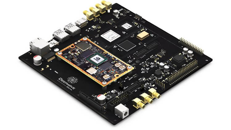
As expected, the AIR-T is not a cheap with it coming in at US$5,699, and this is with a 10% discount off the MSRP. However, the AIR-T is likely to be more of interest to high end industry and university researchers who have research money to spend. Also, compared to Ettus E310/N310 and LimeNET Mini SDRs which have built in non-GPU based computing platforms and similar SDR performance, the AIR-T could be seen as reasonably priced assuming that the software and drivers for it are decent. In the future we expect to see the price of similar SDR-AI development boards eventually reduce down to hobbyist level prices.
The basic idea behind the AIR-T is to combine a 2x2 MIMO SDR transceiver with a NVIDIA Jetson TX2 GPU that can be used to run artificial intelligence (AI) software fast. They will include software that will allow GNU Radio and Python code to be easily ported to the GPU architecture.
Why build tomorrow’s tech with yesterday’s signal processing tools? The Artificial Intelligence Radio - Transceiver (AIR-T) is a fully integrated, single-board, artificial intelligence equipped, software defined radio platform with continuous frequency coverage from 300 MHz to 6 GHz. Designed for new engineers with little wireless experience to advanced engineers and researchers who develop low-cost AI, deep learning, and high-performance wireless systems, AIR-T combines the AD9371 RFIC transceiver providing up to 2 x 2 MIMO of 100 MHz of receiving bandwidth, 100 MHz of transmitting bandwidth in an open and reprogrammable Xilinx 7 FPGA, with fast USB 3.0 connectivity.
The AIR-T has custom and open Ubuntu software and custom FPGA blocks interfacing with GNU Radio, allowing you to immediately begin developing without having to make changes to existing code. With 256 NVIDIA cores, you can develop and deploy your AI application on hardware without having to code CUDA or VHDL. Freed from the limited compute power of a single CPU, with AIR-T, you can get right to work pushing your telecom, defense, or wireless systems to the limit of what’s possible.
The Artificial Intelligence Receiver - Transceiver (AIR-T) SDR
A corner reflector antenna is basically a monopole antenna with a metallic 'corner' reflector placed behind it. The reflector helps the monopole collect signals over a wider aperture resulting in signals coming in stronger from the direction that the corner is pointing at. In past posts we've seen a homemade tinfoil corner reflector used to improve reception of the generic stock RTL-SDR monopole antenna, and a larger one was used in a radio astronomy experiment to detect a pulsar with an RTL-SDR.
Recently The Thought Emporium YouTube channel has uploaded a video showing how to build a large 2 meter 3D corner reflector out of readily available metal conduit pipes and chicken wire. While the antenna has not been tested yet, they hope to be able to use it to receive weather satellite images from GOES-16, to receive moon bounce signals, to map the Hydrogen line and to detect pulsars.
Back in early 2016 we posted about a journalist who used an RTL-SDR to gather ADS-B data about the type of aircraft used at the world economic forum in Davos. The idea was to help highlight the vast wealth and power of the attendees by showing off their heavy use of private aircraft.
Now more recently Laurent Bastien Corbeil has published a similar article in Motherboard (a Vice News tech magazine) explaining how he tracked police and military planes at this years G7 summit which was held in Canada in early June. Laurent used an RTL-SDR Blog V3 with the small dipole antenna attached to a window to gather ADS-B data from all the aircraft activity during the summit.
ADS-B is a radio system used on modern aircraft which broadcasts the aircraft's current GPS location and other data such as aircraft identifiers. It is now used extensively by air traffic controllers as it is significantly more reliable than traditional radar. With a simple RTL-SDR it is possible for anyone to track and plot ADS-B data on a map, and this is how tracking sites like flightradar24.com and flightaware.com work.
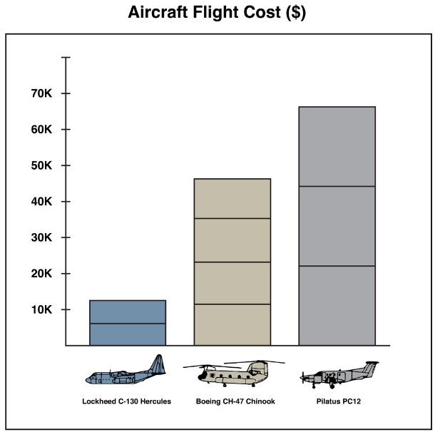
From his collected data he was able to spot several interesting aircraft such as Canadian Air Force Chinooks, C130 Hercules', RCMP Pilatus', a military Bombardier jet, and a coast guard Bell 427. He also notes that while he was able to spot Donald Trumps Marine One helicopter with his own eyes, the ADS-B data was not present, indicating that more important military aircraft do not broadcast ADS-B for security reasons.
In the article Laurent makes estimates of the costs of operating these aircraft, and makes some guesses on the type of mission flown by some of the aircraft.
G7 Aircraft Flight Costs (Data by Laurent Bastien Corbeil, Graphics by Marvin Lau)
Over on YouTube w2aew who has many excellent videos explaining various radio topics has uploaded a new video that talks about the basics of bias tees, and shows some applications and examples. In the video he demonstrates using a bias tee to add DC voltage to a serial signal, measure the RF performance of a BJT transistor, and to tune a remotely tunable 'screwdriver' antenna.
On receiver radios bias tees are commonly used to power remote LNA's (low noise amplifiers) or active antennas by putting DC power onto the coax cable. Ideally an LNA should be placed closer to the antenna as this will help reduce the loss caused by coax cable. Often the antenna is far away from the receiver on a roof or attic where there is no power supply. A bias tee solves that by allowing the coax cable to be used for DC power.
We note that our RTL-SDR Blog V3 dongle has a built in bias tee that can be activated in software.
#284: Basics of RF Bias Tees including applications and examples