moRFeus: A Low Cost Wideband Signal Generator and Frequency Mixer

During development of the Outernet project the engineering team developed several tools to help them in their RF testing. One tool that they created has now been developed further into a commercial product that they are calling 'moRFeus'. moRFeus is a small handheld RF signal generator and frequency mixer. It can be used to generate an RF tone at any frequency between 85 MHz - 6 GHz and to upconvert or downconvert signals via the mixer with an input/output frequency range between 30 MHz - 6 GHz. This type of tool is useful for people working with RF hardware as it can be used for testing and prototyping.

morRFeus is currently selling for US$149 over on CrowdSupply, and the units are ready to ship out soon. They note that the current price is a special, and that it may be increased in the future. We think that this is a fairly good deal considering that similar products can cost much more. If you are interested in the technical details the datasheet includes figures on phase noise and conversion losses. There is also a user guide that explains how the buttons work, and what each screen on the menu is for.  The morRFeus press release reads:

Outernet launches sales for wideband frequency converter and signal generator with complete field-level configuration.

Today, Outernet announced the launch of moRFeus - a wideband (30MHz - 6GHz) frequency converter and signal generator with complete field-level configurability. The product is available on Crowd Supply for $149. The price will increase after the 30-day launch campaign.

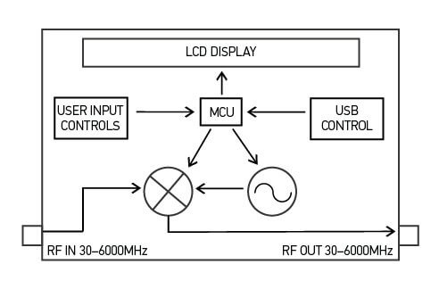
The device has an LCD display and button interface for complete field-level configuration - from setting the LO frequency to toggling between mixer and generator mode, and more. It’s in a precision-milled all-aluminum enclosure for durability and aesthetics.

moRFeus was built for hams and hackers, people with a traditional amateur radio background, as well as a makers and researchers that are interested in RF experimentation. It was designed for easy integration into a wide variety of RF projects.

In mixer mode, moRFeus enables dynamic frequency up- and down-conversion. In generator mode, it is one of the most, if not the most, affordable tools to generate a stable +/-2.5 ppm CW signal. Additional information on features, specifications, and performance metrics can be found in the datasheet.

The team already has 100 units in stock and another 900 are going through final assembly and quality assurance in Chicago. The first 100 units will ship one week after launch and orders beyond the initial stock will ship within 30 days of the close of the campaign, or earlier.

Outernet has been working on novel RF projects since the founding of the company in 2014. moRFeus was developed because from an internal need for a wideband field-configurable frequency converter for testing purposes. The company identified a huge gap in the market for a solution that met the needs of others with similar problems add their own. Outernet’s founder describes the development process:

“The idea was hatched about a year ago because we needed an easy, quick way to dynamically up-and down-convert the various radios we were experimenting with for a new product. By the summer of 2017, we had our first prototype and functional firmware. The design still required some slight tweaking. The current version of moRFeus is its third iteration. Oddly enough, the last phase of the project, industrial design, ended up being the most time-consuming. We worked with a local designer/machinist with decades of experience to come up with a custom-made all-aluminum enclosure.”

For more information and to purchase moRFeus, visit Crowd Supply.

Furthermore the product features, description, and also some of the applications and use cases for moRFeus are quoted below:

Features

  • RF Input Frequency: 30MHz–6GHz
  • RF Output Frequency: 30MHz–6GHz
  • LO Frequency: 85MHz–5400MHz
  • Fractional-N Synthesizer
  • LO Step Size: 1.5–3Hz1
  • 2.5 ppm precision TCXO
  • USB programmable
  • Generator/Mixer Function Toggle
  • Input IP3 +23dBm
  • Small, Portable Form Factor
  • Adjustable Mixer Bias Current
  • LCD Display With Backlight Feature
  • Button Control Interface
  • Dimensions: 88mm x 38mm x 68mm
  • Weight: 7.4 oz

Product Description

moRFeus is a 30MHz–6GHz programmable Fractional-N wideband frequency converter and generator designed for low spurious emissions and dynamic configuring of the LO frequency. moRFeus is designed for easy integration into popular RF environments using SMA connectors and is powered using an external micro-USB 5V supply. The LCD display and button interface provide a dynamic way to program the mixer LO frequency in the field with a step size of 1.5–3Hz.1 The device is USB programmable, enabling automatic operation from a PC (must be running Linux). Dynamic toggling between mixer and generator modes adds to field-level functionality. An optional bias voltage of 5V is available via RF choke to the mixer input to supply active antenna systems.

Applications

  • Wideband Radios
  • Distributed Antenna Systems
  • Diversity Receivers
  • Software Defined Radios
  • Frequency Band Shifters
  • Point-to-Point Radios
  • WiMax/LTE Infrastructure
  • Satellite Communications
  • Wideband Jammers
  • Remote Radio Heads
  • Frequency Up/Down Conversion
  • Automated Test Equipment (ATE)
  • Wireless Communication Systems
moRFeus Block Diagram

Review and Testing

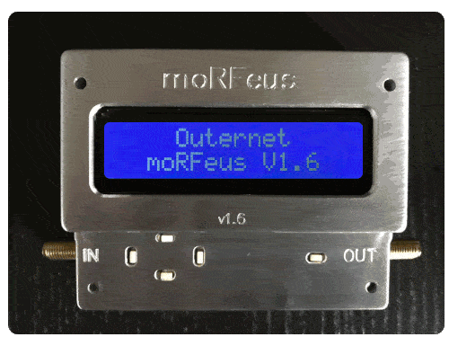
The Outernet team sent us a moRFeus unit for testing a few days ago. It comes in a portable 3.5 x 2.7 x 1.5 inch (8.9 x 6.9 x 3.8 cm) conductive milled aluminum enclosure and weighs 7.4 ounces (210 grams). The construction is very solid, and should easily survive being thrown around in a carry bag, although we'd still advise caution as the LCD screen is not protected by a window.

The unit is powered via a standard micro USB port. After connecting a USB cable the unit immediately powers up shows a frequency selection screen on the LCD display. Five small buttons are used to control the interface, and we found it very easy to adjust the output frequency using these buttons.

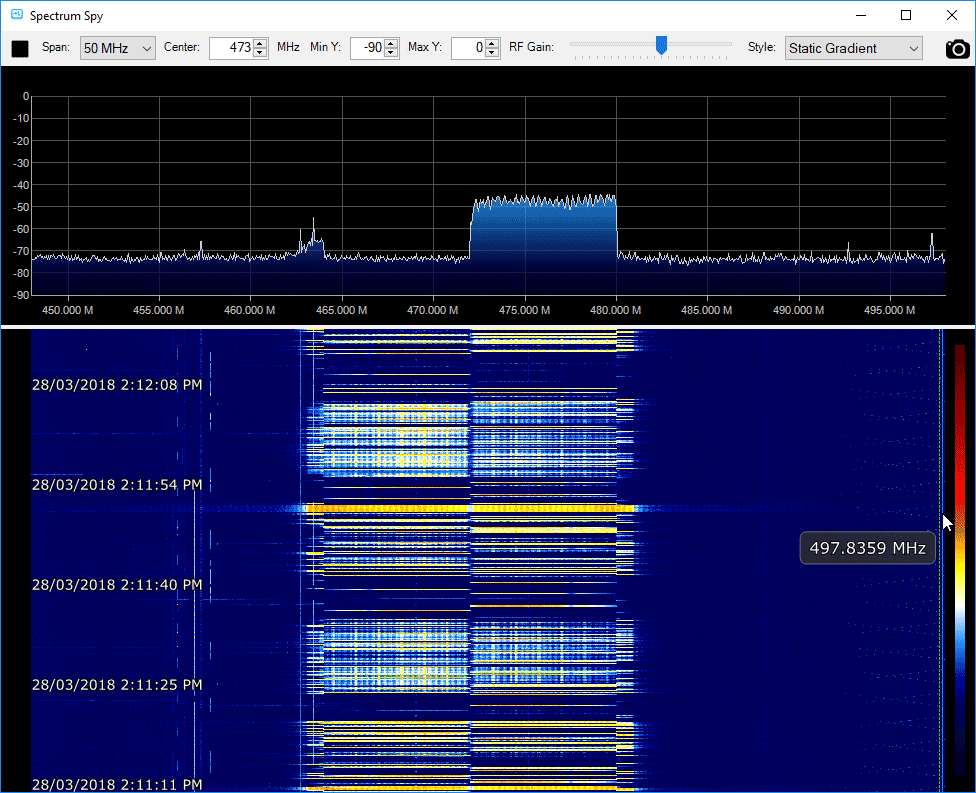
Using the interface the unit can be switched between the "Generator" and "Mixer" modes. In the generator mode moRFeus simply generates a CW tone at the desired frequency. In the mixer mode moRFeus takes an input signal, mixes it with the generated tone and puts the result on the out port. Mixing a signal with a tone is the core concept behind devices like upconverters, downconverters and tuners. For example, by generating a mixing tone at 2 GHz with the moRFeus, we are able to view 2.4 GHz WiFi signals at 2.4 GHz - 2 GHz = 400 MHz.

In the screenshot below we set moRFeus to run in mixer mode with the LO frequency set at 2 GHz. This allows us to view an active WiFi signal at 2.475 GHz using an Airspy and the SpectrumSpy software. The Airspy can only tune up to 1.8 GHz by itself, so it can't view the WiFi band directly. Of course to use as a proper downconverter filtering is required to remove any images and interfering signals, but by being able to easily change the LO frequency you are able to move the signals around quite easily to avoid images or interference.

Unfortunately one limitation is that moRFeus' lowest input frequency is 30 MHz, so it can't be used to upconvert HF signals.

Viewing a 2.4 GHz WiFi signal on an Airspy by using moRFeus as a downconverter.
Viewing a 2.4 GHz WiFi signal on an Airspy by using moRFeus as a downconverter with LO set to 2 GHz.

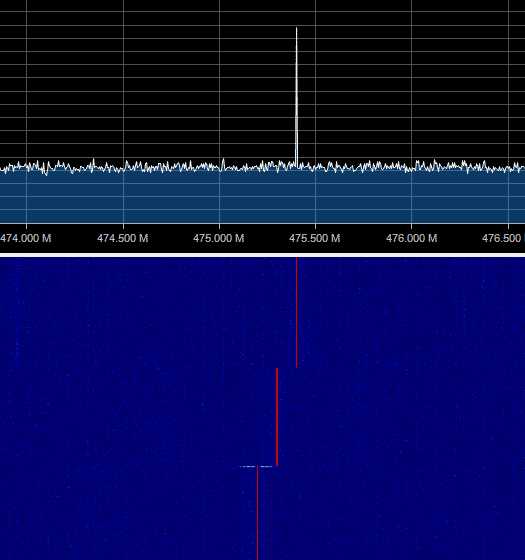
moRFeus also works well as a standard RF signal generator, and we were able to get a clean CW tone on any frequency between 85 MHz - 6 GHz.

moRFeus as a RF signal generator

moRFeus also shows up a a device on the PC, and the team write that it is possible to control it programatically via Linux, however documentation for this does not exist yet although it is scheduled to be released later. We would love to see a sweep feature which should be possible with PC control.

In conclusion if you are looking for a low cost signal generator or mixer to use in your experimental RF projects, then moRFeus certainly does seem like a good deal. A tool like this is very handy to have in your RF kit.

Explaining and Demonstrating Jam and Replay Attacks on Keyless Entry Systems with RTL-SDR, RPiTX and a Yardstick One

Thank you to Christopher for submitting to us an article that he's written for a project of his that demonstrates how vulnerable vehicle keyless entry systems are to jam and replay attacks. In the article he explains what a jam and replay attack is, the different types of keyless entry security protocols, and how an attack can be performed with low cost off the shelf hardware. He explains a jam and replay attack as follows:

The attacker utilises a device with full-duplex RF capabilities (simultaneous transmit and receive) to produce a jamming signal, in order to prevent the car from receiving the valid code from the key fob. This is possible as RKEs are often designed with a receive band that is wider than the bandwidth of the key fob signal (refer Figure 3, right). The device simultaneously intercepts the rolling code by using a tighter receive band, and stores it for later use. When the user presses the key fob again, the device captures the second code, and transmits the first code, so that the user’s required action is performed (lock or unlock) (Kamkar, 2015). This results in the attacker possessing the next valid rolling code, providing them with access to the vehicle. The process can be repeated indefinitely by placing the device in the vicinity of the car. Note that if the user unlocks the car using the mechanical key after the first try, the second code capture is not required, and the first code can be used to unlock the vehicle.

In his demonstrating the attack he uses the RTL-SDR to initially find the frequency that they keyfob operates at and to analyze the signal and determine some of it's properties. He then uses a Raspberry Pi running RPiTX to generate a jamming signal, and the YardStick One to capture and replay the car keyfob signal.

Jam and Replay Hardware: Raspberry Pi running RpiTX for the Jamming and a Yardstick One for Capture and Replay.

An Intro to RTL-SDR: Technical DSP Concepts Explained

Over on his blog Ajoo has posted a very comprehensive introduction to the technical concepts behind RTL-SDR, as well as any other SDR in existence. His post first goes through the basic communications theory and mathematical concepts required to understand the technical concepts behind software defined radio. He then goes on to specifically discuss the RTL-SDR and how it works internally, mentioning what the major components do and providing useful block diagrams.

In part II of his introduction he moves on to the software. Here he starts to explain a bit about librtlsdr and how the RTL-SDR drivers and codebase is put together. Further on he explains higher level software such as rtl_test, rtl_fm, rtl_sdr, the pyrtlsdr wrapper and how it could be used to demodulate FM.

If you're looking at diving deeper into SDR theory then Ajoo's posts are excellent starting points. Note that the theory explanations come at about an undergraduate University level of complexity, and thus these posts are mostly for people wanting a deeper understanding of SDR. To simply use an RTL-SDR to receive signals such a deep level of understanding is not required.

In a future post which is not yet available, Ajoo will introduce GNU Radio and show how to demodulate FM signals. It appears his goal is to work his way to an understanding of how GPS L1 signals work.

One of Ajoo's block diagrams explaining the RTL-SDR behavioral model.

New SDR# Plugin: Toolbar Menu Plugin

Eddie Mac has just released another useful plugin for SDR# called "Toolbar Plugin". This is an accessibility improvement plugin that simply puts many of the plugin controls on the SDR# toolbar. This eliminates the need to constantly open and close plugin panels on the left.

The plugin includes controls for setting the demodulation mode, changing the FFT display settings, a direct frequency entry text box, frequency stepper buttons, an SNR level meter, squelch controls, analog/digital preset buttons, screen grabber controls, and time slot selectors for the TETRA decoder plugin. The analog/digital preset buttons are quite interesting as they allow you to set presets for either analog or digital signals. For example for a digital signal you could set the preset to use NFM demodulation, and to launch the DSD+ application automatically.

More information about this and Eddie's other plugins can be found on his site, and on this forum post.

Some toolbar plugin selections.
Analog/Digital Preset Settings

PiAware Radar – A Traditional Radar-Like Display for ADS-B, and Setting up an ADS-B Cockpit Flight Display

PiAware Radar is a Python script that connects to your PiAware server and uses the received ADS-B data to display a familiar radar-like display (green circle with rotating radius, and aircraft displayed as blips). PiAware is the software used to take ADS-B data from an RTL-SDR dongle running on a Raspberry Pi and feed flightaware.com. A radar-like display is probably not very useful, but it could be used to set up an interesting display that might impress friends. Over on his blog IT9YBG has uploaded a tutorial that shows how to set PiAware Radar up on a Raspberry Pi.

Also on his blog IT9YBG has uploaded another tutorial that shows how to set up 1090XHSI, which is a program that displays an 737 aircraft cockpit simulation using live ADS-B data. The ADS-B data updates the instrument displays in real time, giving you a view of exactly what the pilots might be seeing on their dashboard of their aircraft. We posted about this software in the past, but IT9YBG's tutorial helps make it much easier to set up.

PiAware Radar
PiAware Radar
1090 XHSI 737 Cockpit Simulation from ADS-B Data

GridTracker Now Available on Windows, Mac and Ubuntu (Debian)

In early February we posted news about the release of a program called GridTracker. GridTracker is a live mapping program for WSJT-X which is a software decoder for low power weak signal ham communications modes such as FT8, JT4, JT9, JT65, QRA64, ISCAT, MSK144 and WSPR. Although these are low power modes, the protocols are designed such that even weak signals can potentially be received from across the world. Mapping the received signals can be interesting as it may give you an idea of current HF propagation conditions.

Previously GridTracker was Windows only software. However recently GridTracker was updated to now include support for Mac and Ubuntu (Debian) operating systems as well. This is great news as it makes it much easier to set up a portable GridTracker screen on a portable computer like a Raspberry Pi.

GridTracker Mapping out Weak Signal Communications.

Video Tutorial on Decoding FT-8 and RTTY with an SDRplay RSP1A

Over on YouTube radio content creator Techminds has recently started a series that shows how to decode various signals using an SDR such as the SDRplay RSP1A. The first video explains what FT-8 is and shows how to decode it using the WSJT-X software. FT-8 is a modern digital HF ham mode that is designed to be receivable even in weak signal reception. However, the amount of information sent in a FT-8 message is small, so it is not possible to have a full conversation, and you can only make contacts.

In his second video Tech Minds explains RTTY and also shows how to decode it. RTTY is another much older mode that is used by the military as well as hams. To decode it he uses Digital Master 780 which is a program included in the Ham Radio Deluxe software.

Decoding FT-8 With WSJT-X And A SDRplay RSP1A SDR Receiver

Decoding RTTY With Digital Master And A SDRplay RSP1A SDR Receiver

Radio For Everyone: Testing the RTL-SDR.com Triple Filtered ADS-B LNA, Amplified Coketenna

Akos, author of his blog 'Radio for Everyone' has recently reviewed our new RTL-SDR.com Triple Filtered ADS-B LNA. In the review he compares our ADS-B LNA against another external ADS-B LNA by Uputronics and against the FlightAware Prostick and Prostick+. The tests use the external LNA's plugged directly into the dongle in order to more fairly compare against the FlightAware dongles which have LNA's built in to the dongles themselves. From his results the RTL-SDR.com ADS-B LNA appears to have near identical results with the Uputronics LNA, and slightly better results compared to the FlightAware dongles. Akos has not yet tested the main use-case of the LNA, which is to use it at the end of a run of coax cable, however he plans to do this in a future test. Also in his second post Akos shows how to build a simple amplified Coketenna using our ADS-B LNA.

On the subject of ADS-B performance we note that there are two ways to set up a system for optimal reception (apart from the antenna). The first is to place the computing and radio devices (such as a Raspberry Pi and RTL-SDR) as close to the antenna as possible (leaving a ~1m coax run to avoid local interference from the Pi). For this type of setup it is cheaper to use a FlightAware Prostick Plus RTL-SDR dongle since this has an ADS-B LNA built into it. However, the disadvantage is that you may need to set up a Power over Ethernet system, or find a remote power source, and possibly place the Pi in a difficult to service location such as in an attic or up a mast.

The second option is to use an external ADS-B LNA close to the antenna, and run coax down to the computing device which is positioned in a more accessible location. The LNA will negate any losses in the coax cable, and with high enough gain on the LNA, using quality coax is not such a high requirement since those losses are negated by sufficient LNA gain. Both methods will yield similar excellent performance.

Tested ADS-B LNA's and ADS-B RTL-SDR Dongles