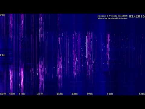
The WebSDR from the University of Twente, Netherlands is a wideband HF SDR that is accessible from all over the world via the internet. It was first activated in 2008 making it the very first WebSDR ever. The creator of the service Pieter-Tjerk de Boer PA3FWM has recently made available spectrum image archives which show the HF band conditions over the last two years.
The X axis represents the frequency and the Y axis is the time of day, starting at the top. Conventional wisdom about band behaviour can be easily confirmed by watching this video: the 60m, 49m and 41m bands are mostly active after dark, with the 60m and the 49m bands being generally busier during the winter months. The 31m band is most active around sunset, but carries on all night until a few hours after sunrise. The 25m band is active during sunrise and for a few hours afterwards, and around sunset during the winter months, but carries on all night during the summer. Peak activity on the 22m and 19m bands is also clustered bi-modally around the morning and the evening hours, though somewhat closer to the middle of the day than on the 31m and the 25m bands. The 16m band is mostly active during the daylight hours and the 13m band is quiet throughout the year except for the occasional ham contest.
[Fast] Visualising shortwave band activity throughout the year
Visualising shortwave band activity throughout the year
To upgrade to this release, you must update libhackrf and hackrf-tools on your host computer. You must also update firmware on your HackRF. It is important to update both the host code and firmware for this release to work properly. If you only update one or the other, you may experience unpredictable behavior.
Major changes in this release include:
Sweep mode: A new firmware function enables wideband spectrum monitoring by rapidly retuning the radio without requiring individual tuning requests from the host computer. The new hackrf_sweep utility demonstrates this function, allowing you to collect spectrum measurements at a sweep rate of 8 GHz per second. Thanks to Mike Walters, author of inspectrum, for getting this feature working!
Hardware synchronization: It is now possible to wire the expansion headers of two or more HackRF Ones together so that they start sampling at the same time. This is advantageous during phase coherent operation with clock synchronized HackRFs. See the -H option of hackrf_transfer. Thank you, Mike Davis!
A new utility, hackrf_debug, replaces three older debug utilities, hackrf_si5351c, hackrf_max2837, and hackrf_rffc5071.
Power consumption has been reduced by turning off some microcontroller features we weren’t using.
There have been many more enhancements and bug fixes. For a full list of changes, see the git log.
Special thanks to Dominic Spill who has taken over much of the software development effort and has helped with nearly every improvement since the previous release!
One of the most interesting updates is the upgrade to hackrf_sweep. The new firmware allows you to make huge wideband scans of the entire 0 – 6 GHz range of the HackRF in under one second (8 GHz/s). In comparison the Airspy is currently capable of scanning at about 1 GHz/s (although the Airspy author has mentioned that a sweep mode could also easily be added on the Airspy).
To update the drivers and flash the new firmware in Linux:
Flash the new firmware with hackrf_spiflash -w firmware-bin/hackrf_one_usb.bin (or the bin file for the Jawbreaker if you have that version of the HackRF)
Disconnect then reconnect the HackRF.
To install Mike Ossmanns fork of QSpectrumAnalyzer which supports the new hackrf_sweep:
To generate a wideband waterfall image sweep with hackrf_sweep and Kyle Keen’s heatmap.py software:
git clone https://github.com/keenerd/rtl-sdr-misc. Take note of heatmap.py inside rtl-sdr-misc/heatmap.
Scan from 1 MHz – 3 GHz, with a bin size of 100k, LNA gain of 32 and VGA gain of 8: ./hackrf_sweep -f1:3000 -w100000 -l32 -g8 > output_data.csv
Generate the heatmap (can take some time to complete if you have a large data file from a long scan): python heatmap.py output_data.csv heatmap_image.png
We’ve uploaded an 0-6 GHz example waterfall scan image over about 30 minutes which is available at filedropper.com/op4. The png file is 90 MB. A sample of the sweep from 400 – 600 MHz is shown below. Trunking, various telemetry and DVB-T signals are visible.
hackrf_sweep 400 – 620 MHz sample
Some GIF examples of QSpectrumAnalyzer running the new hackrf_sweep in order from 1) 0 – 6 GHz scan, 2) 0 – 3 GHz scan, 3) 0 – 1 GHz scan, 4) 500 – 640 MHz scan, 5) 2.4 GHz WiFi Band are shown below.
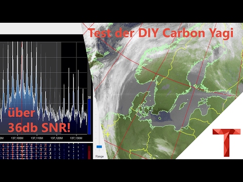
Over on his blog author Manuel a.k.a ‘Tysonpower’ has written about a DIY Carbon Fibre Yagi antenna that he’s built for only 20€. The antenna is very lightweight thanks to a 12mm diameter carbon fibre pipe which is used as the main boom. It also uses 3D printed parts that clamp onto the carbon fibre pipe and hold the metal elements in place. The advantage of the carbon fibre pipe over a PVC one is not only is it lightweight and much easier to hold, but it also stronger, and much less bendy and floppy. The metal elements are welding rods which he found on eBay, and the carbon fibre pipe was sourced cheaply from China with Aliexpress.
A Yagi is a directional antenna with high gain towards the direction it is pointing. You’ll need to hand point the Yagi in the general direction of the satellite as it passes over, but you can expect much higher SNR readings compared to something like a QFH or Turnstile.
Manuel designed his antenna for 2M satellites (NOAA, Meteor M2, ISS etc), and was able to achieve over 36 dB SNR with an RTL-SDR.com V3 receiver, FM Trap and LNA4ALL on NOAA 18 at a 34° max. pass. He writes that the design is easily modifiable for other frequencies too.
To show off the design, construction and performance of his antenna he’s uploaded two videos to YouTube which we show below. The speech is in German, but even for non-German speakers the video is easily followed
The audio codec specifications are not public and is thus not implemented here, so this code has very little use outside of being a good learning tool. But Phil does write that if anyone if able to figure out how to decode the codec, then this code may be a good starting point.
Phil writes:
I wrote this because I wanted to learn about digital broadcasts. Despite the fact that the audio codec used is iBiquity’s proprietary HDC codec, I decided that writing a receiver that could decode the air interface would be a great learning experience.
iBiquity’s HDC codec is supposedly based upon some of the same technologies as HE-AAC codec so it may be possible for some audio codec gurus, given access to the raw HDC audio packets, to write a decoder for the codec.
The receiver is somewhat limited. It only decodes FM MP1 profile transmissions (which happens to includes every IBOC FM transmitter in my area). It is also somewhat limited in the Layer2 packet demultiplexing. It likely needs a strong signal in order to decode signals reasonably well. However it is just enough to get access to the main program stream.
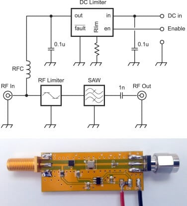
Recently Sivan Toledo wrote in wanting to share an academic paper he wrote together with Itamar Melamed, both from Tel-Aviv University in Israel. The freely available paper describes the design and evaluation of a second-generation front-end for wideband software defined radios. Their front-end helps SDRs optimize reception by providing filtering, a bias tee for mast head amplifiers and also protects the radio against damage from strong signals with an RF limiter. The abstract reads:
In this paper, we describe the design and evaluation of a second-generation front-end unit for wideband sampling radio receivers. The unit contains a surface acoustic wave (SAW) filter to protect the receiver from strong out-of-band signals, an RF limiter to protect both the filter and the receiver from physical damage due to strong signals, and a bias tee with a DC limiter to provide DC power to a masthead low-noise amplifier, if one is used. The unit allows receivers such as those of the universal software radio peripheral (USRP) N-series type to be effectively used in RF environments with weak signals and strong in-band and out-of-band interferences.
Although the front-end is designed for the USRP SDR, it should also work well with RTL-SDR dongles and other SDRs. The authors also write that their design is uploaded and available for PCB printing on CircuitHub.
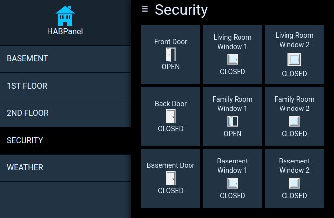
OpenHAB is an open source home automation software program which is designed to interface and manage all the various sensors and systems in an automated house. One problem however, is that many wireless sensors and actuators utilize a proprietary communications protocol that is not supported by OpenHAB.
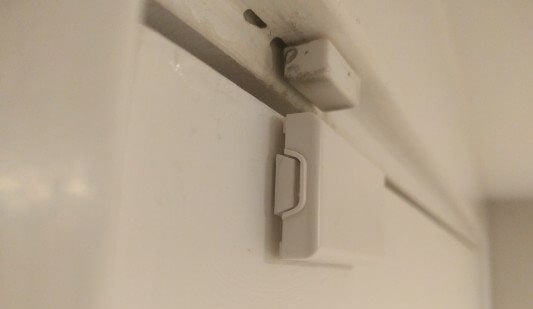
In his home, Dan Englender had several Honeywell 5800 series 345 MHz wireless security door sensors, all of which interface using a proprietary protocol that is not yet implemented in OpenHAB. In order to get around this, Dan decided to reverse engineer the protocol and implement a decoder into OpenHAB himself.
Dan’s four part write up covers the RF capture & demodulation, protocol reverse engineering and implementation into OpenHAB. First he looked up the frequency and bandwidth of the signal via the FCC filing information on fcc.io. Then he captured some packets from a door sensor using his RTL-SDR and GNU Radio, and then wrote a short Python program to decode the protocol and transmit the door open/closed information to OpenHAB. In the future he hopes to optimize the decoder so that it can comfortably run on a Raspberry Pi as the GNU Radio script uses quite a bit of computing power.
The final project is called decode345 and the code is available over on his GitHub.
Honeywell 345 MHz Door SensorCustom Door Sensor Status in OpenHAB
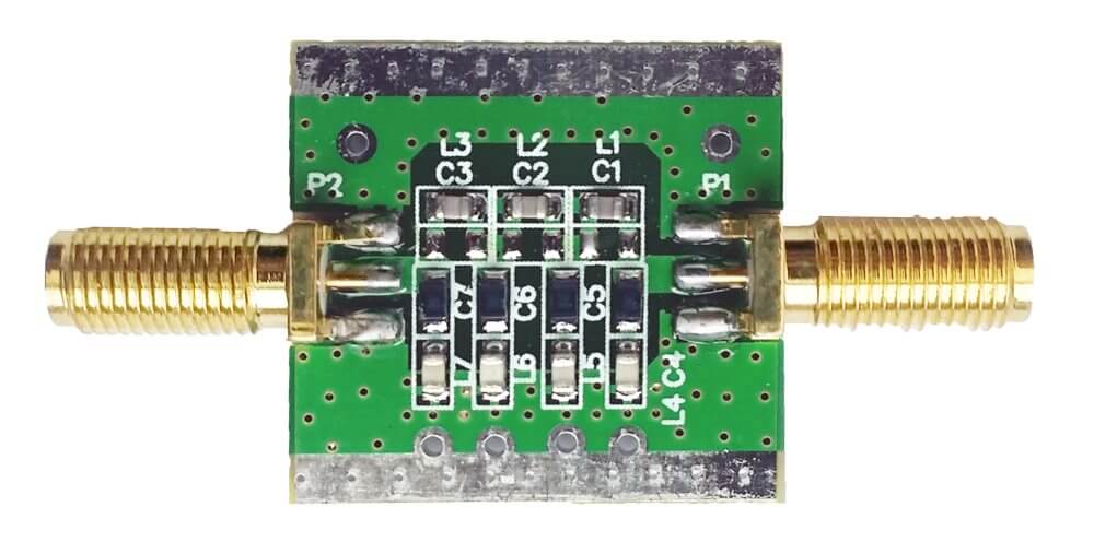
Back in October we released a broadcast FM bandstop filter for removing strong signals in the 88 – 108 MHz region. Today we’re releasing a new broadcast AM high pass filter (BCAM HPF) with a 2.6 MHz cutoff. The cost is the same as the BCFM bandstop filter at $14.95 USD including free international air shipping. Faster shipping options may also be chosen if desired. We’ll eventually have this product on Amazon USA in a few months too, but for now it is only available from our Chinese warehouse.
The filter comes in a 2.8 cm x 2.8 cm x 1.3 cm aluminum enclosure and uses female SMA connectors on each end. Included in the package is also a SMA male to SMA male straight barrel adapter.
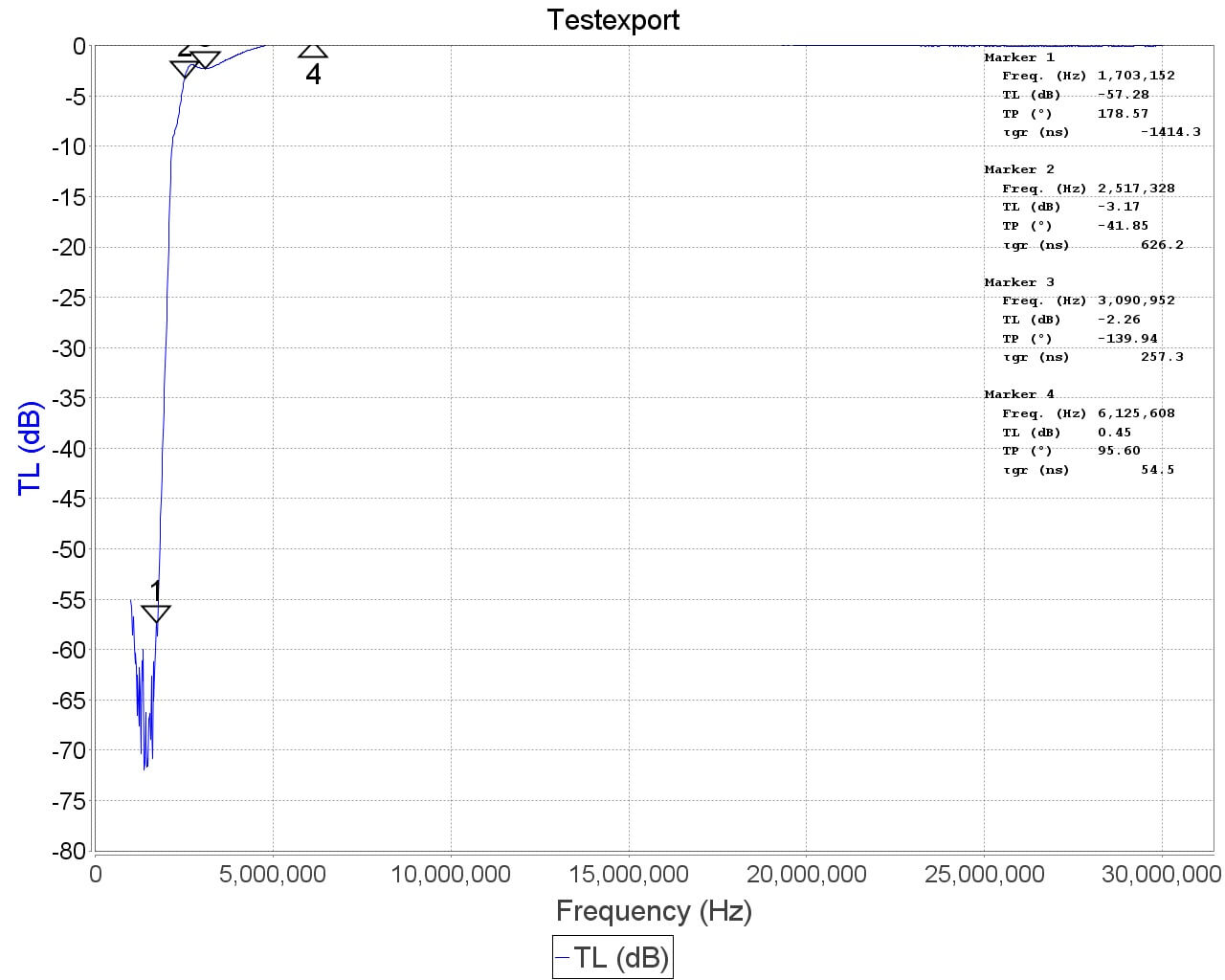
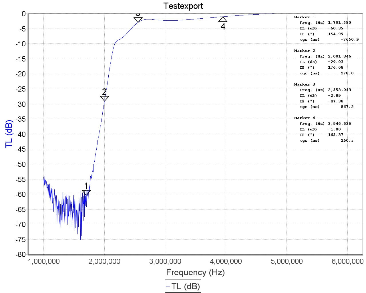
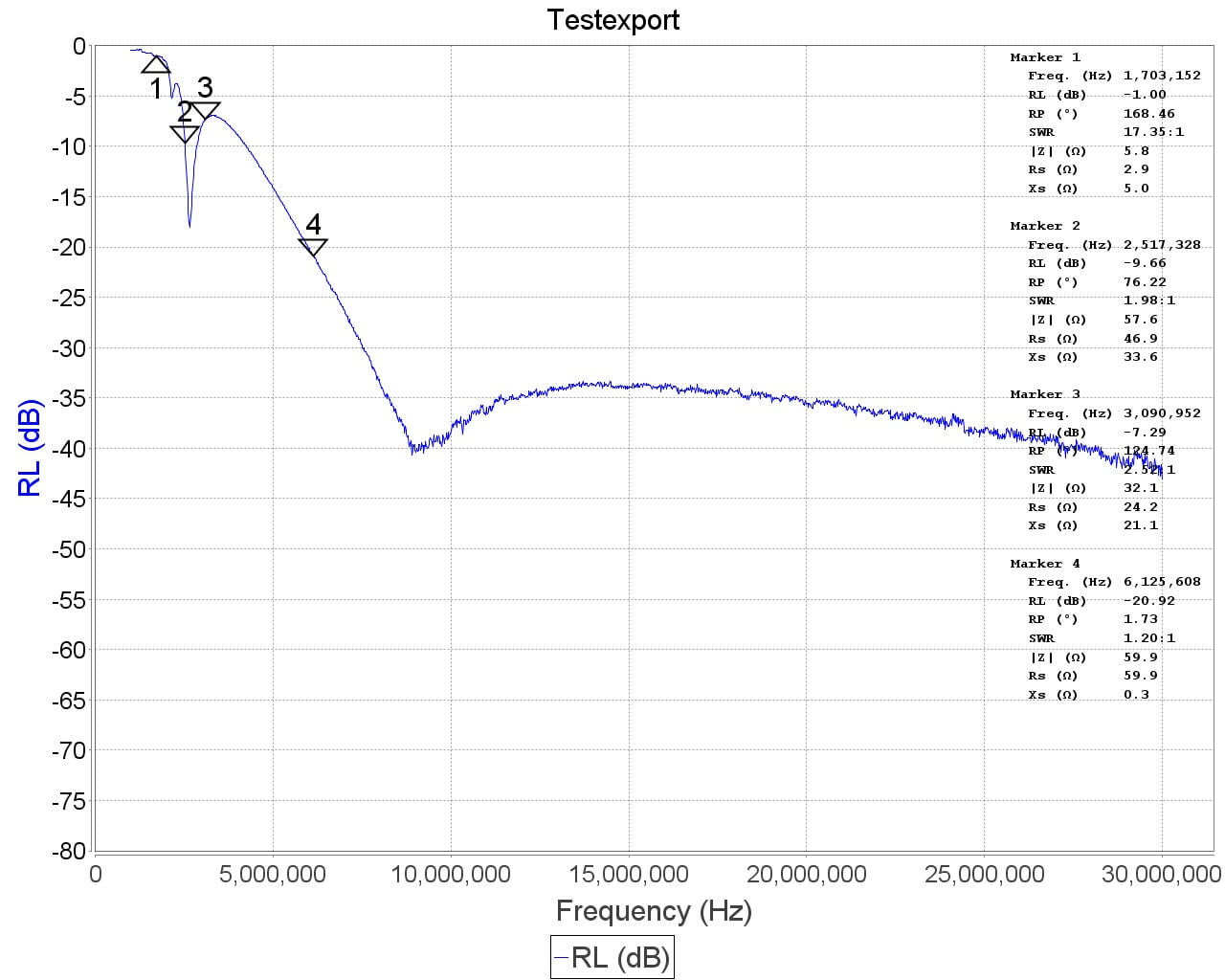
This filter is designed to eliminate broadcast band AM (BCAM) stations by attenuating (blocking) any signals below 1.7 MHz. In reality due to roll-off the filter is usable from about 2.5 – 2.6 MHz and above.
The broadcast AM band exists at around 525 kHz to 1.705 MHz. These signals are usually local, and if you live close to a transmitter they can sometimes be extremely strong. Broadcast AM signals that are too strong can overload your SDR or radio, causing poor reception in other HF bands too. The filter also helps attenuate any other strong VLF/LF/MW interference. Note that this filter is a high pass and not a bandstop, so it will also block VLF signals. Specifications are shown below:
Filter Type: LC High Pass Filter 3 dB Cutoff: 2.5 – 2.6 MHz Attenuation: ~60dB Pass band I.L: Typically well below 2 dB Power Levels: RX power only, cannot pass DC
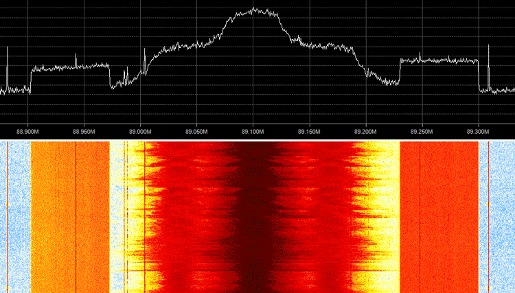
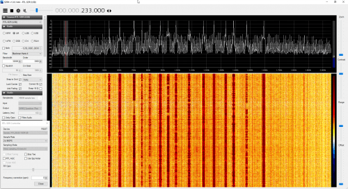
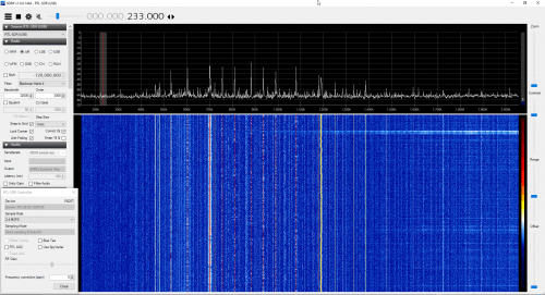
We’ve also uploaded a video below that shows a demonstration of reception when using an RTL-SDR.com V3 dongle in direct sampling mode together with the BCAM HPF. In the video we first compare reception against an upconverter (the Spyverter). It’s worth nothing that the upconverter can receive signals well even without the filter in place. Using the filter does still help the upconverter receive a little bit better but the effect is not shown in the video. Then we simply scroll through the spectrum and listen to a few signals.
RTL-SDR.com V3 Direct Sampling with HPF Demonstration
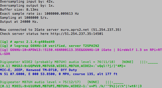
Keith Maton (G6NHU) wrote in and wanted to share his new ready to go APRS RX iGate image for the Raspberry Pi. APRS stands for “Amateur Packet Reporting System”, and is a type of packet radio communications system used by Amateur Radio operators. They often use them to transmit short mail messages, weather sensor updates, track vehicles and for various other purposes. An iGate allows APRS messages to be transmitted over the all world via the internet via a signal chain such as: RF->iGate RX->Internet->iGate TX->RF. To run an iGate you should be a radio amateur with a callsign. A global aggregation of APRS broadcasts received by iGates can be seen at aprs.fi.
An RTL-SDR can be used to receive APRS packets easily and many amateur radio enthusiasts have been setting up APRS RX only iGates using the “direwolf” decoding software. Keith’s image simplifies the process of installing and configuring software significantly by proving a plug and play image that you just burn to an SDcard and plug into your Raspberry Pi. His post also explains how to configure the iGate correctly.
![[Fast] Visualising shortwave band activity throughout the year](https://www.rtl-sdr.com/wp-content/plugins/wp-youtube-lyte/lyteCache.php?origThumbUrl=https%3A%2F%2Fi.ytimg.com%2Fvi%2FVioW3bQsq0M%2F0.jpg)
![[EN subs] Yagi Antenne aus Carbon bauen (140mhz, 3 Elemente) - DIY](https://www.rtl-sdr.com/wp-content/plugins/wp-youtube-lyte/lyteCache.php?origThumbUrl=https%3A%2F%2Fi.ytimg.com%2Fvi%2FbNsvUdHIliI%2F0.jpg)