Meteor M-N1 Satellite Wakes up from the Dead

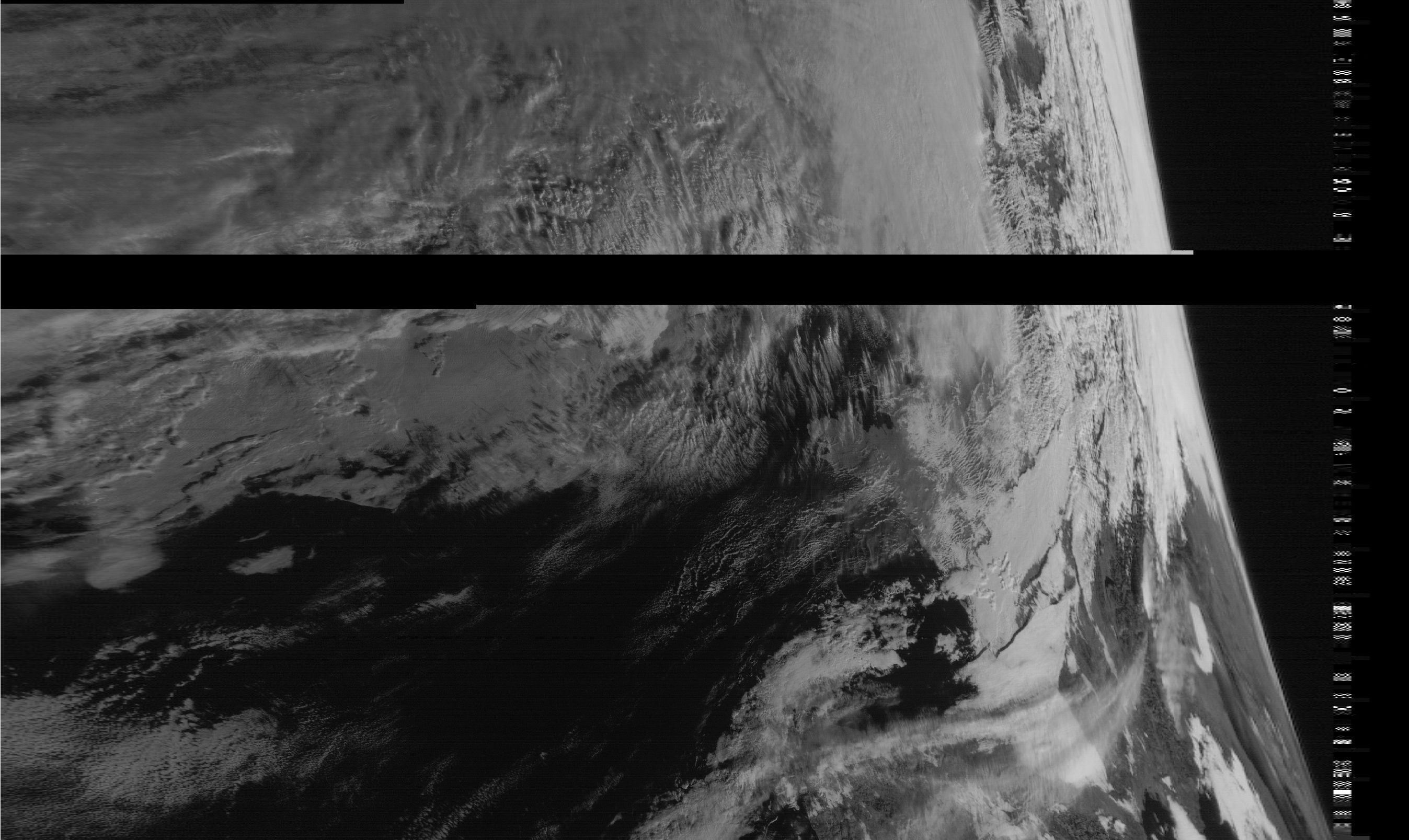
RTL-SDR.com reader Happysat recently wrote in with some news. A few days ago a weather satellite image decoding enthusiast from Argentina was waiting for a pass of the Russian Meteor M-N2 satellite when he discovered a strong LRPT signal at 137.1 MHz, even though the Meteor M-N2 satellite was not in sight yet. It turns out that the signal was coming from the old Meteor M-N1 satellite which was supposed to have been shut down in September 2014 due to several problems it had. The received signal is strong enough to produce a good black and white weather image, but because the satellite is not longer physically stable, sometimes the Earth’s curve can be seen in the images.

Recent images received from the resurrected Meteor M-N1 weather satellite.
Recent images received from the resurrected Meteor M-N1 weather satellite. The stabilization system has failed so the earth’s curve can be seen.

The exact reason as to why it is transmitting again is unknown, but it is speculated that it is due to a breakdown of the chemicals in the batteries. Last year we posted about how sometimes satellites which have been decommissioned and shut down can spontaneously begin transmitting again when their batteries undergo a chemical change due to thousands of failed recharge cycles. The chemical change allows the batteries to conduct electricity from the solar panels directly to the electronics, which on Meteor M-N1 could be reactivating the transmitters and imaging sensors. If this is what happened then the satellite will only be able to transmit during the day.

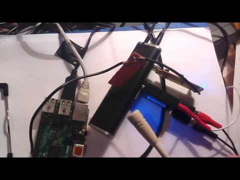
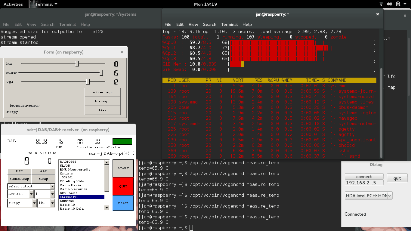
The Meteor M-N2 satellite is the currently official active satellite. It transmits weather satellite images with the LRPT protocol which can be received and decoded with an RTL-SDR dongle. We have a previous post on this showing an offline LRPT decoding tutorial and more recently a tutorial showing how to decode LRPT in real time. The same processes can now be adapted to the resurrected Meteor M-N1 satellite by choosing the 80K symbol rate option in the LRPT decoder.

Happysat who submitted this news originally writes:

A few days ago some guy in Argentina was waiting for the pass of Meteor M-N2 and on SDRSharp waterfall he did see LRPT Digital signals on 137.100MHz, but Meteor M-N2 was not in sight yet…

This relatively strong signal was coming from the defunct Meteor M-N1 satellite left out of control in September 2014 last year and was shutdown, although LRPT Transmissions in the past where very limited and sporadic.

Meteor M-N1 did suffer from many problems at this was the first Russian digital weather satellite in the M-series onboard many hardware in experimental stages.

After this report I tried also to capture some signals from Meteor M-N1 (some other amateurs already got small portions of images) but the satellite only transmits in direct sunlight, batteries are not charging any more.

Indicating maybe like the other older ‘deadsat’ some chemical reaction did occur inside the batteries so the power goes from the solar panels directly to the transmission parts.
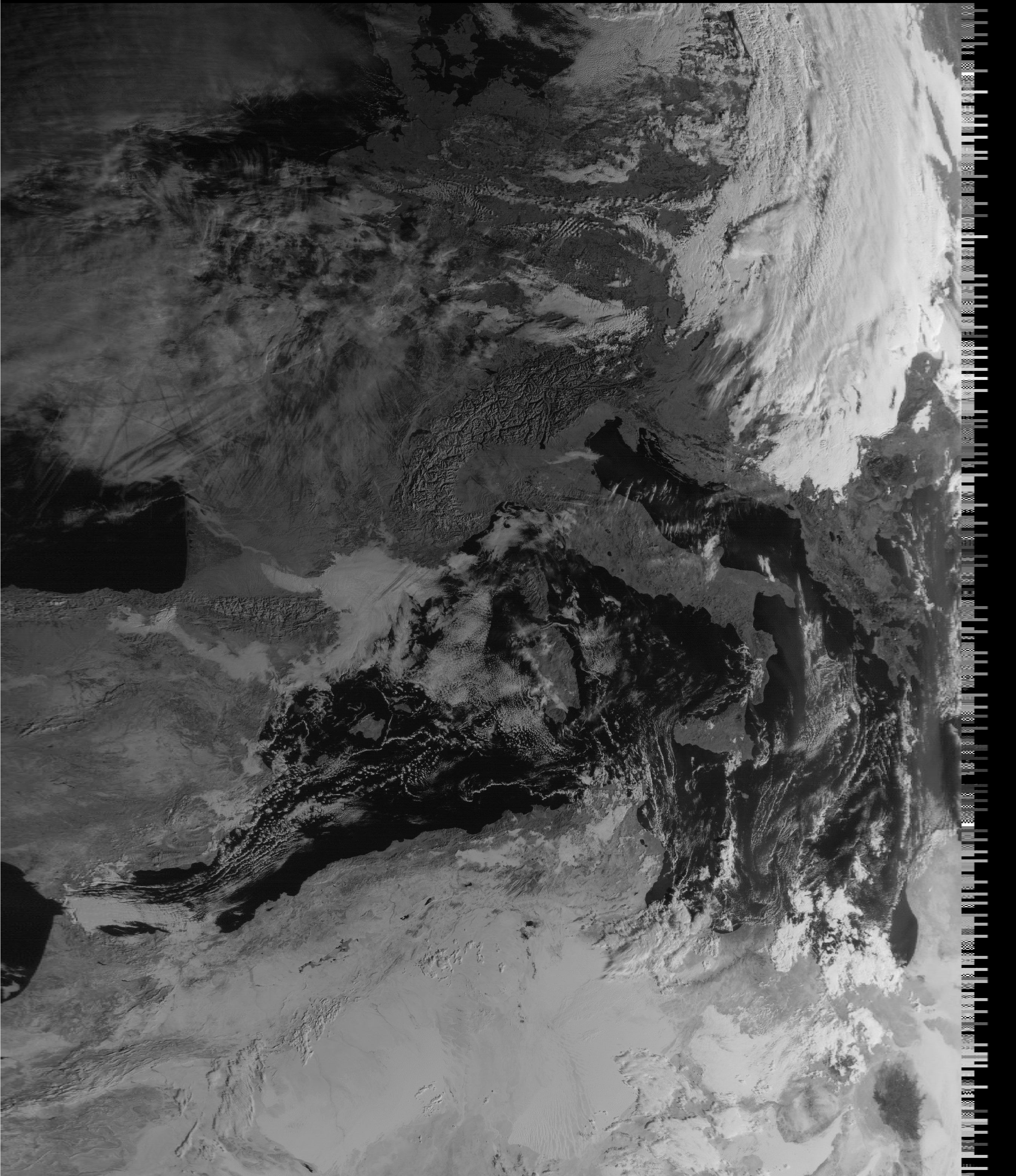
It did happen before, mostly on older satellite’s only a unmodulated carrier is present when the sunlight conditions are optimal.

Surprisingly after I did record and process the 80K symbol rate QPSK signal from Meteor M-N1 with Vasili’s excellent QPSK Plugin a very nice image was generated!

Not only the sunlight provides power to the transmission part but also there is enough power to activate the imaging system which is quite amazing!

Visible channels 1-2-3 are fully working but the image is only Black and White Calibaration of the sensor are not okay so no color images can be created.

Nevertheless its a very nice addition for current LRPT weather amateurs and a big surprise its even working better when nobody controls it 😉

Because the stabilisation system failed there is no proper correction to orientate the camera and on some passes one can see the earths curve!

There are some conflicting reports about the status of Meteor M-N1 found on the internet:

Status Inactive
Details on Status (as available)

  • MSU-MR was functional with limitations (calibration issues and higher noise level in the IR channels).
  • MTVZA-GY instrument was functional with limitations due to failures of on-board memory and atmospheric sounding channels.
  • Severjanin instrument non-operational.
  • DCS was functional with limitations due to interferences to signals from ground sources.
  • GGAK-M was operational with significant limitations.
  • LRPT was functional with limitations due to information compression errors.
  • Finally, the stabilisation system failed on 23 September 2014 and the instruments could longer be operated.

On October 1, 2014 Meteor-M No 1 was withdrawn from operational use and transferred to the study of the chief designer. The decision on further operation of the spacecraft will be taken upon completion of the research program.

Its not clear the problems did got solved, and I ‘think’ M-N1 started a second life on his own. Time will tell how long the satelitte will function.

Some details:

https://directory.eoportal.org/web/eoportal/satellite-missions/m/meteor-m-1

http://planet.iitp.ru/english/spacecraft/meteor-m-n1_eng.htm

The Meteor M-N1 Satellite.
A color image received on Meteor M-N1. Colors may not be perfect.  Submitted by Jan.
A color image received on Meteor M-N1. Colors may not be perfect. Submitted by Jan.

Watching ATSC TV with an SDRplay SDR and GNU Radio

ATSC is the digital HD TV standard used within the United States and Canada. It is 6 MHz wide so the RTL-SDR with its maximum bandwidth of about 2.8 MHz cannot decode this signal. However, higher end SDR’s such as the SDRplay, Airspy and HackRF have larger bandwidths that can easy cover 6 MHz.

One SDRplay owner was able to figure out a way to decode ATSC by using a decoder written in GNU Radio. With the process the author used we note that other wide band SDR’s such as the Airspy and HackRF should also be capable of achieving the same results.

The process the author used was to first record a RAW IQ WAV file in HDSDR in Windows, making sure that any DC spike correction is applied. The WAV file is then opened in a premade GNU Radio flow graph in Linux and processed into an MPEG file. The process is not real time. The authors article shows a step by step tutorial on how its done.

In an update post to his results the author also notes that to successfully do a recording at the maximum SDRplay bandwidth of 8 MHz a RAM disk or perhaps SSD is required so that samples are not dropped.

An ATSC signal shown in HDSDR received with an SDRplay

A modified dump1090 with ADS-B Heatmap and Range Alititude View

Dump1090 is one of the most popular ADS-B decoders that is used together with the RTL-SDR dongle. ADS-B stands for Automatic Dependant Surveillance Broadcast and is a system used by aircraft that broadcasts their GPS positions. It is a replacement for traditional reflection based radar systems. We have a tutorial on using the RTL-SDR to decode ADS-B here.

There is now a forked version of dump1090 by tedsluis that incorporates heatmap generation and range/altitude view. A heatmap will allow you to visualize where the most active aircraft paths in your area are and the range/altitude view allows you to see at what altitudes aircraft typically fly at in different locations. The software logs aircraft data in a CSV file, and then after collecting enough data a second program can be used to generate the heatmap. The full explanation of the software and instructions for installing and using it on a Raspberry Pi Linux system together with PiAware are posted on the flightaware.com forums.

A heatmap of aircraft flight paths.
dump1090-mutability with Heatmap ADS-B and range altitude view

Improving Reception with the Stock RTL-SDR Antenna by Building a Corner Reflector

Last week a reader of RTL-SDR.com wrote into us to let us know about some experiments that he had been performing with the telescopic stock antennas provided in our RTL-SDR dongle packages. The reader had built a corner antenna reflector in order to improve reception in one direction. We are posting his write up and results below:

This tutorial will discuss the use of a Corner Reflector with a monopole antenna, i.e. the stock RTL-SDR antenna. To keep this tutorial concise, the reader is encouraged to study the Wikipedia pages for details about Corner Reflector Antennas, Dipoles and Monopoles.

Corner Reflector Antennas are very easily constructed from 2 A4-sized cardboard panels, covered with tinfoil. This allows for a foldable and transportable external reflector to the built-in wifi antennas of a laptop, which are located on the upper corners of the display. 

The reader is pointed to the fact that corner antennas are based on a Dipole, where the stock RTL-SDR antenna is a Monopole, so some adjustments will have to be made, which is discussed and explained later in this text. If there are real antenna specialists reading this, they are encouraged to do a more thorough writeup on the exact mechanism of a monopole-based corner reflector antenna, as there was little information to be found on the internet.

The experiment started as an attempt to receive a DVB-T signal centered around 506 MHz, from a mast about 10 miles away. Indoors. This should have given a clear and strong signal, but alas, the signal was very weak.

Initial reception of the DVB-T signal with the stock antenna and no modifications.

Reading up on Monopoles and their need for a ground plane, the magnetic base of the 14 cm long antenna was placed on a metal cooking pot. The signal was a lot stronger. (The middle part of the waterfall plot above.) Clearly a wooden table is not much of a ground plane.

Next a Corner Reflector was made from tinfoil and a cardboard box, much to the dismay of the resident Feline Overlord that had seized it. 🙂 A triangular piece was added for rigidity and as a ground plane. The Monopole antenna was placed on the ground plane triangle in the middle of the 90° corner and at the correct distance from the fold in the reflector. i.e. the Focal Axis, but the gain was less than the theoretical 10dB so this setup was unsuccessful. (Upper part of waterfall plot above.)

The breakthrough came when I wanted to study the effect of a larger ground plane. For this I put the corner reflector sideways and put the monopole on the outer edge to reduce possible reflections from the standing panel. There was only a slight effect compared to the cooking pot, so I decided to progressively move the monopole towards the back panel in order to see if the additional reflection would get some more gain. When I reached about 10 cm distance from the panel, the waterfall plot exploded with a very powerful signal! See the picture below for the transition from wooden table to the sideways configuration. (On top of the waterfall plot there is some residual from the ground plane cooking pot test.)

DVB-T signal with corner reflector.

The setup looks like this:

04-sideways-setup
For a few days I was baffled as to why the corner reflector behaved this way. It had already dawned on me that the diagonal distance from the fold till the antenna tip was 14 cm in this configuration, so 1/4 WL. It was only after I visualized how a monopole works, that I understood: a 1/4 WL monopole is physically a quarter wavelength open ended resonator. i.e. at the base/feed point the electric current is maximum and the voltage minimum. At the tip it is reversed, with maximum voltage and zero current. See this page for details: http://www.radio-electronics.com/info/antennas/vertical-antennas/quarter-wavelength.php

Alternatively, the polar plot of a Corner Reflector Antenna also shows that the signal is weakest/zero in the direction of the panels, where the monopole base is located, while the maximum signal is along the center line between the 2 panels, which is where the tip of the monopole is located. Hence the signal *difference* over the monopole is thus maximized and this way it works best. As stated in the beginning, if an antenna expert can write up a better explanation, please contact the maintainer of the RTL-SDR Blog.

In retrospect, the original setup I tested could not work optimal since the entire monopole is irradiated equally if it is aimed along the Focal Axis. Moreover it was suspected that the mirror image antenna that makes a monopole work, was distorted because of the electrical contact between the triangular ground plane and the reflector panels. A test with an isolated triangular ground plane was planned but has now been permanently shelved.

For those who want to re-create the experiment, these are the reflector dimensions:

  • 2 panels of 42*25cm, joined along the longest side.
  • 36*25*25cm triangle at the bottom. This should give a 90° angle between the 2 largest panels.
  • The tinfoil can be wiped smooth and attached with some glue.

So to summarize;

  • Make sure you have a good ground plane!
  • A Corner Reflector Antenna can be constructed at frugal cost with a cardboard box and tinfoil. Larger reflectors are better, especially in the plane perpendicular to the Monopole, so it is better to have wide reflectors in stead of high reflectors.
  • Make sure the base of the stock monopole antenna is located in an area with low signal strength and the tip is located in an area of maximum signal, therefore maximizing the *difference* between base and tip of the Monopole. Usually this means perpendicular to the Focal Axis of the reflector panels.
  • Distances and Monopole lengths can easily be adjusted for various frequency ranges, making this a very versatile modification or enhancement to the stock antenna.

Speculation: Since there is a focal Axis rather than a Point (i.e. like a Parabolic Dish), the sideways configuration might be more suitable for tracking a moving satellite across the horizon, ideally at 45° azimuth.

Spektrum: New RTL-SDR Spectrum Analyzer Software

Recently a reader of RTL-SDR.com, Pavel wrote in to let us know about a new program called “Spektrum” which he has written. Spektrum runs on Windows and Linux and turns an RTL-SDR dongle into a spectrum analyzer in a similar way to rtl_power GUI front ends and RTLSDR Scanner. However one key improvement is that it is based on a version of rtl_power that has been modified by Pavel in order to make it more responsive and remove the need to wait until a full sweep is completed before you can see any results. The modified version of rtl_power can be found at https://github.com/pavels/rtl-sdr.

Spektrum also has an additional “relative mode” feature. This allows Spektrum to be easily used together with a wideband noise source to measure things like filter characteristics and the VSWR of antennas. See our previous tutorial on this here, but note that in our tutorial we used Excel instead of Spektrum to do relative measurements.

The Processing language was used to create Spektrum and Pavel has also released his processing library for accessing rtl_power functionality over at https://github.com/pavels/processing-rtlspektum-lib/releases.

Ready to use releases of Spektrum for Windows and Linux 64-Bit OSes can be downloaded from https://github.com/pavels/spektrum/releases. Note that there may be a bug with the current release which causes only a gray window to show, but we’ve contacted the author about it and it may be fixed soon.

Spektrum: A new spectrum analyzer program for the RTL-SDR

Building a Ham Transceiver with an RTL-SDR, Raspberry Pi and Rpitx

A few days ago we posted about RpiTx, a piece of software that allows you to turn your Raspberry Pi into a multi purpose transmitter by modulating the output on one of the GPIO pins.

Now over on YouTube user HA7ILM has uploaded a video showing his related software qtcsdr. Qtcsdr runs on the Raspberry Pi and interfaces with an RTL-SDR dongle and RpiTx to create a simple transceiver radio. In the video HA7ILM shows the software in action by using a microphone and RTL-SDR plugged into the Raspberry Pi, and showing the microphone transmitting via RpiTx and being received via the RTL-SDR.

Qtcsdr can be downloaded from https://github.com/ha7ilm/qtcsdr.

As always with this type of thing only transmit if you are licensed and take care with the transmitted distance and filter the antenna output when transmitting over a distance that is further than your room. Also regarding this, on the qtcsdr GitHub page the author mentions that a Raspberry Pi shield called the QRPi filter + amplifier is currently in development (white paper).

QTCSDR Control GUI
QTCSDR Control GUI
Testing qtcsdr: receiving the transmission with an RTL-SDR via attenuator

Creating a DIY 88-108 MHz FM Trap

One of the most problematic strong signals you can encounter is regular 88 – 108 MHz broadcast FM stations. They transmit at high power and can cause overloading and intermodulation problems on simple receivers such as the RTL-SDR. This means that FM stations can prevent you from receiving signals even when you are tuned far away from the broadcast band.

The simplest solution to reducing strong FM stations is to build an FM trap. This is simply a band stop filter that blocks frequencies between 88 – 108 MHz from entering your radio. Adam (9A4QV), the creator of the popular LNA4ALL and several other RTL-SDR compatible products has recently uploaded an article showing how to build a home made FM trap out of cheap common parts.

Adams article goes through and explains the design of a FM trap and how to use freeware software to aide in the calculations. The final FM trap designed by Adam uses just 3 common SMD capacitors and 3 hand wound coils. His filter attenuates more than 30dB in the 88-108 MHz range with an insertion loss of less than 1dB up to 1.7 GHz.

A DIY FM Trap
A DIY FM Trap

SDR-J Now Compatible with the Raspberry Pi 2

The popular software DAB (Digital Audio Broadcast) decoder SDR-J has recently been updated and can now run on the Raspberry Pi 2. In addition the author has also added experimental DRM decoding capabilities to his shortwave receiving software. The author writes about the Raspberry Pi 2:

The Raspberry PI 2 has a processor chip with 4 computing cores. By carefully spreading the computational load of the handling of DAB over these cores it is possible to run the DAB software on the Raspberry PI 2.

In my home situation the – headless – Raspberry PI 2 is located on the attic and remotely controlled through an SSH connection using the home WiFi on my laptop in my “lazy chair”. To accomodate listening remotely, the DAB software on the Raspberry PI 2 sends – if so configured – the generated PCI samples (rate 48000) also to an internet port (port 100240). On the laptop then runs a very simple piece of program reading the stream and sending it to the soundcard

DAB is a digital audio protocol that is used in some countries as a digital alternative to broadcast FM (music stations). SDR-J is a suite of programs that includes the ability to decode DAB, FM, and several shortwave modes such as AM, USB, LSB, PSK, RTTY, WeatherFax, SSTV, BPSK, QPSK, CW, NavTex (Amtor-B), MFSK, Domino, Olivia, Hell, Throb and now DRM. It can directly connect to RTL-SDR receivers as well as other hardware such as the Airspy and SDRplay.

Screenshot of SDR-J running on the Raspberry Pi 2.