Project Horus 55: Live Video from a High Altitude Balloon

Project Horus 55 was a project that involved creating a high altitude balloon with payload that could broadcast live video down to ground station observers, as well as creating the ground station receive hardware. On March 7th 2021 the balloon was launched and ground station observers successfully received the live video.

The transmission hardware onboard the balloon was a Raspberry Pi Zero which captured and compressed the video, and a LimeSDR Mini which broadcast a DVB-S signal at 445 MHz. Power amplification was provided by an 800mW LDMOS amplifier. On the ground station side, RTL-SDRs were used as the receiving hardware and SDRAngel as the software. Although high gain auto tracking Yagi's were used by the main ground station team, it's interesting to note that the balloon chase team were also able to receive the video with a simple vechicle mounted turnstile.

In the video below Mark VK5QI who was one of the people behind the project discusses the setup before the launch.

Live Amateur TV from 100,000 feet!

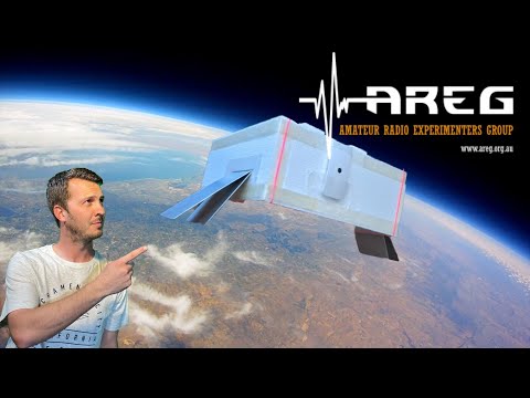
The video below shows the launch and some of the live video received.

PiccoloSDR: A Simple SDR From a Raspberry Pi Pico

The Raspberry Pi Pico is a $4 microcontroller board. Recently radio amateur Luigi Cruz discovered that the ADC on the Pico could be used as a simple direct sampling software defined radio, with a bandwidth of 250 kHz. The idea is that the ADC data is made available to a PC connected to it's USB port via emulated TCP/IP protocol. On the PC side, GNU Radio is then used to process the received ADC data, turning it into an SDR.

Applications of a direct sampling SDR with only 250 kHz are limited, as it's only possible to receive up to the LF band, and there are not many signals that low in frequency. However, it is an interesting project that can be used to demonstrate a simple SDR. If you're interested in trying it out, the code is available over on GitHub.

PiccoloSDR Project - Using the Raspberry Pi Pico RP2040 as an SDR - First Test with GNU Radio.

[Also seen on Hackaday]

GPU Accelerated RTL-SDR Radio Interferometer Code For Radio Astronomy

Evan Mayer (@millijanskys) has recently released some code called “effex” that allows you to use two RTL-SDR dongles as an interferometer for radio astronomy and other experiments.

The hardware used is two RTL-SDR Blog V3 dongles with synchronized oscillators via the selectable clock headers, two 1420 MHz filtered LNAs, a splitter and noise source consisting of a 50 Ohm load and wideband LNA, and a NVIDIA Jetson Nano GPU single board computer. We note that Evans code should also run on our KerberosSDR with some modifications to enable the built in noise source during calibration.

To add to this Evan wrote to us explaining how this code might be used:

You could start to do some basic interferometric imaging by adding more coherent channels. This is exactly what Daniel Estévez just did with USRPs and GNU Radio at the Allen Telescope Array.

Did you see the “picture” of the supermassive black hole shadow released by the Event Horizon Telescope collaboration in 2019? The “ring of fire” or “donut” image? Daniel’s image and that image were created by “aperture synthesis.”

In aperture synthesis, the signals from each pair of antennas distributed across an area can be cross-correlated to measure one component of the 2D Fourier transform of the radio brightness distribution on the sky. But, you need coherent receivers (or REALLY good time stamps) to cross-correlate the signals from the antennas. Get enough pairs of antennas, and you can start to more fully sample the 2D Fourier space of the sky brightness distribution, which you can then use to reconstruct a real image.

This is how distributed radio arrays like the EHT work, as well as localized ones like ALMA or LOFAR.

Receiving Video Directly from a SpaceX Falcon 9 Rocket + Scott Manley Video

Last week we posted about how several users on Reddit & Twitter worked together to receive and decode text telemetry from the SpaceX Falcon 9 rocket launch using a HackRF, 1.2m dish with custom 2232.2 MHz feed and GNU Radio. In that thread it was hinted that the text telemetry was only a small portion of data contained in the entire signal. It turns out that the remaining data is the SpaceX engineering video feed which is often shown in the official live coverage streams.

Over on Reddit user /u/TRGFelix writes how he was able to receive and decode the video with his own low cost setup involving an Airspy Mini SDR, TV MMDS downconverter and the ubiquitous low cost WiFi grid dish that we've often used for GOES satellite reception and for Hydrogen Line radio astronomy. The software used was the SatDump decoder created by /u/Aang253 which builds on the research done by @r2x0t:

So today at 10:21UTC i got my own recording of Falcon9 video feed downlink on S band 2272.5MHz and with u/Aang253's software SatDump i could easily decode it from the recording straight down to mxf, avi or mp4 video file! Even with very simple recieving setup!

Setup used for receiving was simple wifi grid mesh dish antenna (100x60cm) on a tripod with old MMDS TV downconvertor and Airspy MINI. here is a photo of the setup few minutes before launch But of course its doable without convertor with SDR such as HackRF , two SPF5189Z LNAs and same antenna or even TV dish with DIY S band feed!

Software used for recording was great performing opensource SDR++ by u/xX_WhatsTheGeek_Xx link here https://github.com/AlexandreRouma/SDRPlusPlusS oftware used for decoding was u/Aang253's Satdump software which i will link later as it still needs readme written and confirm it runs without bugs! UPDATE - LINK: https://github.com/altillimity/SatDump

Original MXF video together with CADU file and I/Q file recording 6MSPS int16 here. https://files.altillimity.com/Falcon%209%20OK9UWU/

TRGFelix is also on Twitter as @OK9UWU and he has posted images of his setup, and part of the video he decoded. TRGFelix notes that he is working on a tutorial which we are very eager to see!

It's extremely interesting that we can see views of the liquid oxygen floating around inside the stage two tank which is not shown during the official live streams.

As a bonus, this story was also covered by the very popular space YouTuber Scott Manley who has put out a great video popularizing the discovery and touching on a few interesting points such as how SpaceX may be legally required to encrypt these videos in the future (but hopefully not!).

How Amateur Radio Fans Decoded SpaceX's Telemetry & Engineering Video

CENOS Antenna Design and Simulation Software Looking for Testers

Back in March 2020 we posted about CENOS, a company creating a new antenna modelling and simulation design package. Back then they were offering applications to beta test the software for free. CENOS has now reached V1.0 status, and they are now wanting to enroll another 300 testers. The benefit to the testers is that they will receive a 90% lifetime discount on the software, and testers who provide lots of active feedback will be granted free licenses.

CENOS Antenna Design version 1.0 will be available for closed testing starting from March 17, 2021.

During the free 14-day testing trial, users are expected to share their feedback about the software and usability, thus making an impact on further software development. 

In reward, they will get a generous discount or lifetime-free-licenses (for best contribution), once the software is available for public use (we expect to launch it shortly after rigorous testing completes).

More details will be announced on March 17!
 
Sign up here:
Software benefits
 
​CENOS is fast-to-learn and easy-to-use specialized antenna design simulation software for budget-sensitive customers.

CENOS integrates FreeCAD geometry editor to handle geometry of any complexity, provides built-in utilities for handy design of microstrip antennas and arrays, feed networks, wire antennas (including import of NEC files), and arbitrary 3D structures. FreeCAD also allows to import CAD files from external editors like Autodesk Inventor or similar.

CENOS ensures automatic meshing, as well as allows building manual mesh of any detalization level in the specially designed FreeCAD workspace.

For antenna calculation, the current software version utilizes FEM solver to provide accurate simulation for geometries of any complexity, including multi-port, high Q and other cases. Already now, CENOS R&D is pointing to combining the FEM solver with MoM and FDTD methods to provide a unique, optimized (fast and accurate) solution for any particular case.

CENOS provides very powerful visualization capabilities that includes full visualization of fields and graphs powered by Paraview, spreadsheet for data like S11, VSWR, reflection coefficient, etc, and pdf report.

That all makes CENOS a good alternative to well-known general purpose software like HFSS, CST, FEKO and Comsol for budget-sensitive customers looking for specialized antenna design simulation software.
Software functionality
• One-stop software: from CAD geometry to full visualization of results and analysis
• Desktop (on-premises) installation for Windows 7-10
• CENOS leverages open-source tools to ensure full stack of CAD/CAE software: FreeCAD, GetDP, ParaView
• User experience optimized for RF antenna design
• Supports the use of CAD geometry files prepared by any design program (.step or .iges formats)
• Pre-defined templates for basic antenna geometries
• Full-stack geometry editor powered by FreeCAD
• Material database, possibility to add and save custom materials

Simulation capabilities
• Wide range of antennas, antenna arrays, geometries of any complexity, inhomogeneous structure
• Finite element method (FEM) solver optimized for high frequencies
• Lumped port type, multiple ports (feeds) with phase shifts
• Frequency diapason (wide, multiband) 
• Ports: S11, VSWR, power, reflection coefficient, impedance, reactance, and resistance
• Fairfield pattern: directivity (gain), radiation intensity
• Antenna: Electric field, magnetic field, vector plots 
• Frequency-dependent dielectric constant and loss tangent
 
… all you need for antenna design in an easy-to-use way, because this is the software specialized on RF antenna design with full spectrum of necessary functionality. And we are constantly working to add more value.
 
Hardware requirements
You don’t need a supercomputer to run antenna design simulations with CENOS. Intel i5 or i7 (or similar) are good enough. The faster processor you have, the faster calculation will go.

We recommend to have at least 16Gb RAM to calculate 3D cases, 32Gb is better. Actually, the more RAM you have, the bigger (more complex) 3D geometries you can simulate. Some of our customers use 128 Gb machines and that’s like for rocket-science-cases. MS Windows OS.
CENOS Antenna Simulation
 

Frugal Radio: Monitoring VHF Airband Aviation Frequencies at the Airport

Rob from Frugal Radio has recently uploaded the next video in his airband monitoring series. In this video Rob explains various airband communications that can be received from the airport, and explains about needing to be in the line of sight of an airport in order to receive them.

He goes on to explain signals and airport radio communications channels such as ATIS, Clearance Delivery, Tower, Arrivals (Approach), Departures, Radar and Terminal communications. The video provides various examples of these communications being received with an SDRplay software defined radio.

Monitoring VHF Airband Aviation Frequencies at the Airport

GNU Radio Amateur Radio Meeting: A Look at Project 25 (P25) Digital Radio

Over on their YouTube channel GNU Radio have uploaded a recent talk by Aaron Rossetto titled "A Look at Project 25 (P25) Digital Radio". The talk explains the North American public safety P25 system in great depth, and is a good watch for anyone looking into details on how the system works in a deeply technical way. He later shows some examples of his P25 decoding and recording setup. Slides can be found here, and the video is posted below.

Agenda: In this presentation, I will introduce Project 25 digital radio, with a strong emphasis on its use in North American public safety trunked radio systems, and to describe experiments monitoring and decoding P25 traffic using GNU Radio code.

  • What is Project 25?
  • A brief introduction to trunked radio
  • Diving into the P25 protocol
    • Modulation
    • Packet framing and encapsulation
    • Packet types
  • GNU Radio and P25 decoding experiments
Amateur Radio Meetup: P25 Trunked Radio

Receiving Shortwave Radiograms with an RTL-SDR and MultiPSK

Shortwave Radiogram's are digital broadcasts of images, text and sometimes HTML files that are regularly broadcast on two shortwave radio stations, WRMI in Florida and WINB in Pennsylvania. The transmissions are produced and presented by Dr. Kim Andrew Elliott, and a schedule can be found on the Shortwave Radiogram website.

Over on his blog Jeremy Clark has been experimenting with receiving shortwave radiograms with an RTL-SDR and upconverter. To do this he notes the transmission schedule on the shortwave radiogram website, and uses SDR# and MultiPSK in MFSK mode to receive and decode the data. Jeremy's post explains the MFSK transmission mode and shows a few examples of radiograms that he's received including a video posted below showing live reception and decoding.

RTL-SDR for Shortwave Radiogram