KerberosSDR is our 4-channel phase coherent capable RTL-SDR unit that we previously successfully crowdfunded back in 2018. With a 4-channel phase coherent RTL-SDR interesting applications like radio direction finding, passive radar and beam forming become possible. It can also be used as 4 separate RTL-SDRs for multichannel monitoring. KerberosSDR is currently in stock and available on the Othernet store.
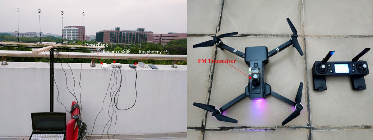
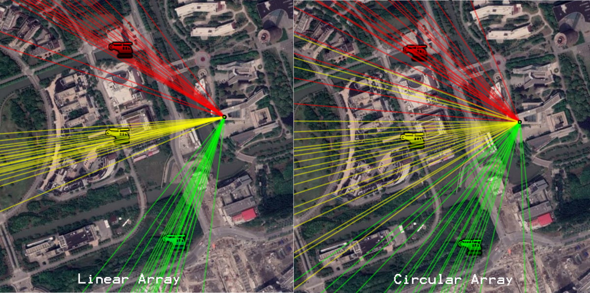
In their experiment they set up both circular and linear antenna arrays for the KerberosSDR, then flew the drone in front of the antenna array while recording the bearings calculated by the KerberosSDR system. The results showed that the KerberosSDR was able to successfully track the drone's bearing with either antenna array, however the linear array produced more accurate results as expected.
We note that a linear array cannot differentiate if an object is in front or behind the array. However, if this knowledge is known it can be used instead of a circular array to get more accurate bearings that are less affected by multipath.
The KerberosSDR is our 4-channel phase coherent capable RTL-SDR unit that we previously successfully crowdfunded back in 2018. With a 4-channel phase coherent RTL-SDR interesting applications like radio direction finding, passive radar and beam forming become possible. It can also be used as 4 separate RTL-SDRs for multichannel monitoring.
In one of our latest tests we've been able to track a weather balloon radiosonde via the direction finding ability of KerberosSDR. These balloons are launched twice daily by meteorological agencies around the world, and the radiosonde carried by the balloon transmits an RS-41 signal continuously throughout it's flight sending back telemetry such as weather information and GPS coordinates. The KerberosSDR tracks the bearing towards the balloon using only the raw signal - it does not decode. Having the actual GPS location from the RS41 data allows us to compare and confirm that the KerberosSDR is indeed tracking the bearing of the balloon.
In this test we used the excellent 4-element dipole array made by Arrow Antennas. In particular we used the 406 MHz element version as the RS-41 signal is broadcast at 403 MHz. The antenna array is mounted on the roof, the KerberosSDR is in the attic connected to a Raspberry Pi 4. Our KerberosSDR Android app is used to plot the bearings. A separate RTL-SDR running on the video recording PC is connected to it's own antenna and is used to receive and decode the RS41 signal. The free software RS41 Tracker is used to decode and map the balloon for location confirmation.
We are currently using the latest beta code in development (unreleased at the time of this post - it will be released within 1 to 2 months) which handles non-continuous intermittent signals better.
Arrow Antennas 4-Element Dipole Array Mounted on Roof
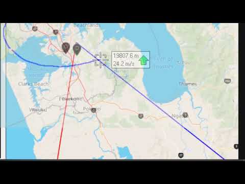
The short video below shows a timelapse of the RS41 decoder tracking a balloon which circled the south of our KerberosSDR. The red line indicates the zero degree direction of the antenna array, while the blue line indicates the estimated direction of the balloon determined via the MUSIC radio direction finding technique.
The GPS balloon map from RS41 tracker is overlayed on top of the KerberosSDR Android app map for clarity via video editing. We can see that it mostly tracks the balloon to within a few degrees. When the blue bearing line diverges this is due to the balloon's line of sight path to the antennas being obscured by terrain, buildings or trees. When this is the case a multipath signal reflecting off surrounding hills tends to become dominant.
In the second short video below the weather balloon tracked northwards. Towards the north, north west and north east we have antenna obstructions in the form of rising terrain, houses and hills, so the overall accuracy is poorer. However, it still tracks within a few degrees most of the time.
Finally the YouTube video below shows the same as the above, but in the second half includes the full screen including the KerberosSDR DoA graphs and SDR# waterfall showing signal strength.
KerberosSDR Tracking a Weather Balloon Radiosonde with Radio Direction Finding
In the future we hope to test with two or more KerberosSDR units producing multiple bearing lines on RDFMapper, hopefully resulting in cross points that can be used to estimate the actual location of the balloon.
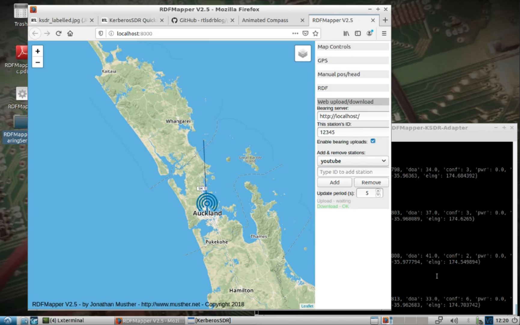
DragonOS is a ready to use Linux OS that includes various SDR programs preinstalled. The creator Aaron also runs a YouTube channel that contains multiple tutorial videos for DragonOS. One of the latest videos he's released is a tutorial that shows how to use one of our KerberosSDR (4x Coherent RTL-SDR) units to set up networked direction finding. To do this he uses our core KerberosSDR DSP software, along with RDFMapper, a third party bearing visualization tool with the ability to display bearing from multiple networked direction finding units.
The tutorial goes through the KerberosSDR software install procedure, shows how to set up the various parameters in the software, and then demonstrates it providing data to the RDFMapper software via our open source pyRDFMapper-KSDR-Adapter program. With this setup, you could run multiple KerberosSDR units around a city and use them to locate a signal source rapidly.
KerberosSDR Uploading Bearing data to RDFMapper
DragonOS LTS/10 Direction Finding Bearing Server (KerberosSDR, RDFMapper)
In addition to the direction finding video he's got another video that shows how to use a KerberosSDR and HackRF to simultaneously monitor various signals like home gas meters, ADS-B data, and 433 MHz ISM band devices using programs like rtlamr, rtladsb and rtl_433. What's particularly interesting is how he uses a program called Kismet to manage each radio on the device.
Jan Hrach of the Faculty of Mathematics and Physics at Univerzita Karlova in the Czech Republic recently defended his Masters thesis titled "Passive emitter tracking". The main theme of the thesis was the use of RTL-SDRs for tracking transmitters via the Time Difference of Arrival (TDoA) technique. TDoA works by having multiple receivers spread out over a region. As long as the receivers are synchronized in time, we can calculate the difference in time that a signal took to arrive at each receiver, which allows us to pinpoint the location of a transmitter. The challenge is in the timing synchronization, and receiver placement. The thesis abstract reads:
We have implemented a TDOA multilateration of transmitters on an unmodified rtl-sdr receiver using transmitters with known location as a timing reference. We present a brief theoretical background and describe the measurement process which includes several approaches that correct the timing and frequency errors between the receivers. Additionally, we have implemented an angle of arrival direction finder using coherent rtl-sdr.
The thesis and associated code is available on the universities website at this link and it is written in English. Jan also does have a presentation available on YouTube, however it is presented in Czech and automated subtitles do not appear to be available. The video and results section of the thesis shows some good results that indicate that transmitters were able to be pinpointed with very good accuracy, however, localization only worked well on signals with good cross-correlation properties, like DVB-T. Only about half the tested broadcast FM stations could be located due to interference, FM being low bandwidth and FM being transmitted at lower frequencies which suffer from reflections and multipath all of which result in poorer correlation.
TDoA results achieved with RTL-SDRs distributed around Prague.
KerberosSDR is our experimental 4-Tuner Coherent RTL-SDR product made in collaboration with Othernet. It can be used for applications such as radio direction finding and passive radar. Currently it's available for US$149 on the Othernet store.
The RDF Mapper software allows you to upload bearings from multiple devices distributed around a city to a public RDF server, and view all the bearings on any internet connected PC. This can allow you to quickly triangulate the location of a transmitter.
Normally you would use RDFMapper combined with an RDF42 to upload bearings, but we've written a simple script that can be used to upload bearings generated by a KerberosSDR onto the server. The RDFMapper software can then be used to visualize those bearings.
The script is based on Python, and can run directly on the Pi 3/4 or Tinkerboard that is running the KerberosSDR, or on another PC that can see the KerberosSDR bearing server if you prefer.
Instructions are available on the GitHub page. Simply set unique station names for each of your distributed units, entry your lat/lon and fixed direction bearing. Then on the RDF Mapper software open the 'Web upload/download' tab and add the unique station ID name. All the other tabs for connecting to a GPS and serial port can be ignored, as those are used for the RDF42.
This script will only work for stationary KerberosSDR units as the lat/lon is fixed. If you want to try radio direction finding in a vehicle, we recommend using our Android App for a better experience. If there is interest, we may also add support for the Android app to upload to an RDFMapper server for mobile bearing uploads.
Notes: RDFMapper runs on the system's default browser and it needs to run in either Chrome or Firefox to work. IE does not work. It also appears that Jonathan processes orders manually, so we just want to note that there may be a delay between payment and receiving the software.
RDF Mapper Software. Plotting bearing data from networked units.
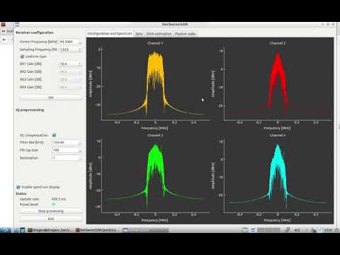
KerberosSDR is our four tuner coherent RTL-SDR product made in collaboration with Othernet. With KerberosSDR applications like radio direction finding and passive radar are possible, and our free open source demo software helps to make it easier to get started exploring these applications. In this post we explore how a simple passive radar setup can be used to measure how busy a neighborhood is in terms of vehicular traffic.
Passive radar makes use of already existing strong 'illuminator' signals such as broadcast FM, DAB, digital TV and cellular. When these signals reflect off a moving metallic object like an aircraft or vehicle, it distorts the signal slightly. By comparing the distorted signal to a clean signal we can determine the distance and speed of the object causing the reflection. Wide reaching digital signals like DVB-T and DAB are often the best illuminators to use. Wideband cellular signals can also be used to detect more local targets.
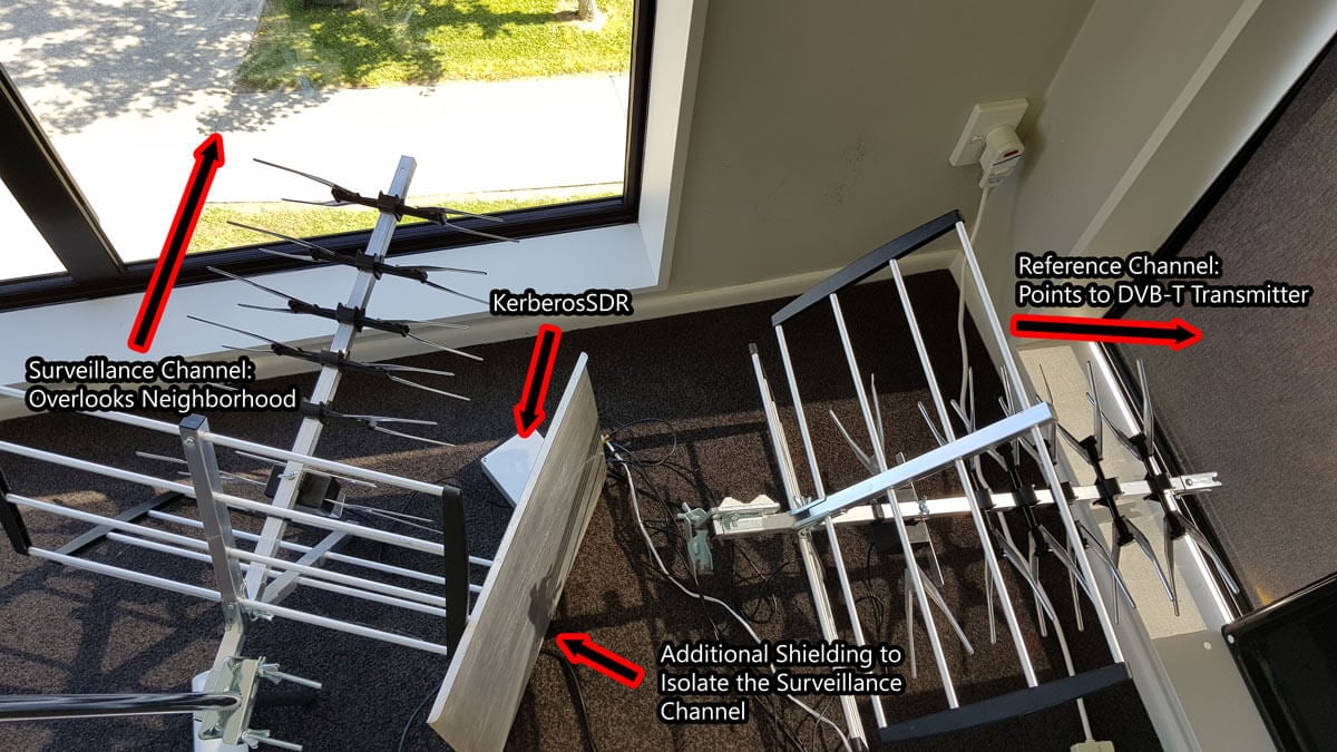
In a simple passive radar system we use two directional antennas such as Yagi's. One Yagi points towards the broadcast tower and receives the clean non-distorted reference signal. This is known as the reference channel. A second Yagi points towards the area you'd like to monitor for reflections, and this is called the surveillance channel.
In our setup we point the reference channel Yagi towards a 601 MHz DVB-T transmitter roughly 33 km away. A second Yagi is placed on a vantage point overlooking a neighborhood. The Yagi's used are cheap DVB-T TV Yagi's that can be found in any electronics or TV retail store (or on Amazon for ~$30 - $60 USD). In the software we used a bandwidth of 2.4 MHz and adjusted the gains for maximum SNR.
It is important that the surveillance channel is isolated from the reference signal as much as possible. We improve the isolation simply by placing a metal sheet next to the surveillance Yagi to block the reference DVB-T signal more. Note that putting the antennas outside will obviously result in much better results. These walls and windows contain metal which significantly reduce signal strength. We also added our RTL-SDR Blog wideband LNA to the surveillance channel powered by a cheap external bias tee to improve the noise figure of the surveillance channel.
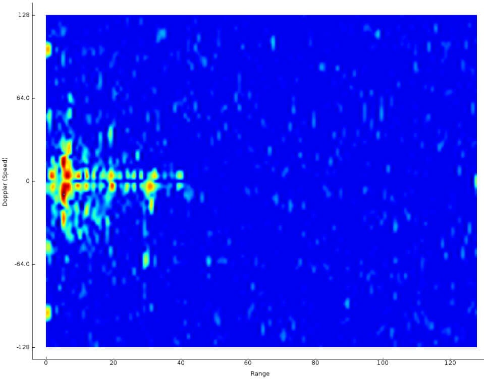
The resulting passive radar display shows us a live view of objects reflecting. Each dot on the display represents a moving vehicle that is reflecting the DVB-T surveillance signal. In the image shown below the multiple colored objects in the left center are vehicles. The X-Axis shows the distance to the object, and the Y-Axis shows the doppler speed. Both axes are relative to the observation location AND the transmit tower location.
Vehicles on the Passive Radar Display
When there are more moving cars on the road during the day and rush hours, there are more blips seen on the passive radar display. Larger vehicles also produce larger and stronger blips. By simply summing the matrix that produces this 2D display, we can get a crude measurement of how busy the neighborhood is, in terms of cars on the road since reflections are represented by higher values in the matrix. We logged this busyness value over the course of a day and plotted it on a graph.
The resulting graph is as you'd intuitively expect. At 6AM we start to see an increase in vehicles with people beginning their commute to work. This peaks at around 8:30AM - 9am with parents presumably dropping their kids off to the neighborhood school which starts classes at 9AM. From there busyness is relatively stable throughout the day. Busyness begins to drop right down again at 7PM when most people are home from work, and reaches it's minimum at around 3am.
Traffic Busyness detected with KerberosSDR Passive Radar
One limitation is that this system cannot detect vehicles that are not moving (i.e. stuck in standstill traffic). Since the doppler speed return will be zero, resulting in no ping on the radar display. The detection of ground traffic can also be distorted by aircraft flying nearby. Aircraft detections result in strong blips on the radar display which can give a false traffic result.
It would also be possible to further break down the data. We could determine the overall direction of traffic flow by looking at the positive and negative doppler shifts, and also break down busyness by distance and determine which distances correspond to particular roads. In the future we hope to be able to use the additional channels on the KerberosSDR to combine passive radar and direction finding, so that the the blips can actually be directly plotted on a map.
If you want to try something similar on the KerberosSDR software edit the RD_plot function in the _GUI/hydra_main_window.py file, and add the following simple code before CAFMatrix is normalized. You'll then get a log file traffic.txt which can be plotted in excel (remember to convert Unix time to real time and apply a moving average)
On this weeks episode of SignalsEverywhere, host Corrosive tests out our KerberosSDR coherent RTL-SDR unit for radio direction finding. If you didn't already know KerberosSDR is our experimental 4x Coherent RTL-SDR product. With it, coherent applications like radio direction finding (RDF) and passive radar are possible. Together with the KerberosSDR direction finding Android app it is possible to visualize the direction finding data produced by a KerberosSDR running on a Pi3/Tinkerboard.
In the video Corrosive uses the KerberosSDR together with the recently updated companion Android app to determine the location of a P25 control channel. By driving around with the app constantly collecting data he's able to pinpoint the location within about 15 minutes.
In addition to his video, Corrosive has also created a very useful calculator that can be used to calculate the required antenna spacing for a circular or linear direction finding array that can be used with the KerberosSDR.
We have just released an updated version of the KerberosSDR Android direction finding app. If you didn't already know KerberosSDR is our experimental 4x Coherent RTL-SDR product. With it, coherent applications like radio direction finding (RDF) and passive radar are possible. Together with the KerberosSDR direction finding Android app it is possible to visualize the direction finding data produced by a KerberosSDR running on a Pi3/Tinkerboard.
The KerberosSDR hardware is currently in preorder status on Indiegogo for the second production batch, and we expect it to be ready to ship out this month. If you preorder then you'll be able to purchase a KerberosSDR at a reduced price of USD$130. After shipping for batch two begins the price will rise to USD$150.
The new version of the KerberosSDR Android app adds the following features:
Heatmap Grid Plotting
Precise TX location pinpointing when enough data points are gathered
Turn by turn navigation to the RDF bearing direction / TX location
Bearing moving average smoothing
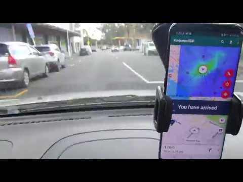
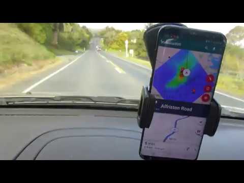
To understand what these features are, we've released two demo videos showing them in action. In the first video we use the new features to find an 858 MHz TETRA transmitter, and in the second video we find a 415 MHz DMR transmitter. The first video explains the new features so we recommend watching that first.
KerberosSDR Radio Direction Finding: Heatmap + Auto Navigation to Transmitter Location Demo 1
KerberosSDR Radio Direction Finding: Heatmap + Auto Navigation to Transmitter Location Demo 2