Listening to February 2017 HAARP Experiments with an HF Capable SDR
This year at the end of February HAARP (High Frequency Active Auroral Research Program) scientists are planning to run several experiments that involve transmission. HAARP is a high power ionospheric research radio transmitter in Alaska, which typically transmits in the 2.7 – 10 MHz frequency region. The transmissions are powerful enough to create artificial auroras in the sky. Due to a lack of funding HAARP research was shut down in May 2013, and then later given to the University of Alaska Fairbanks (UAF) in 2015.
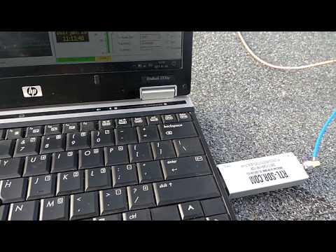
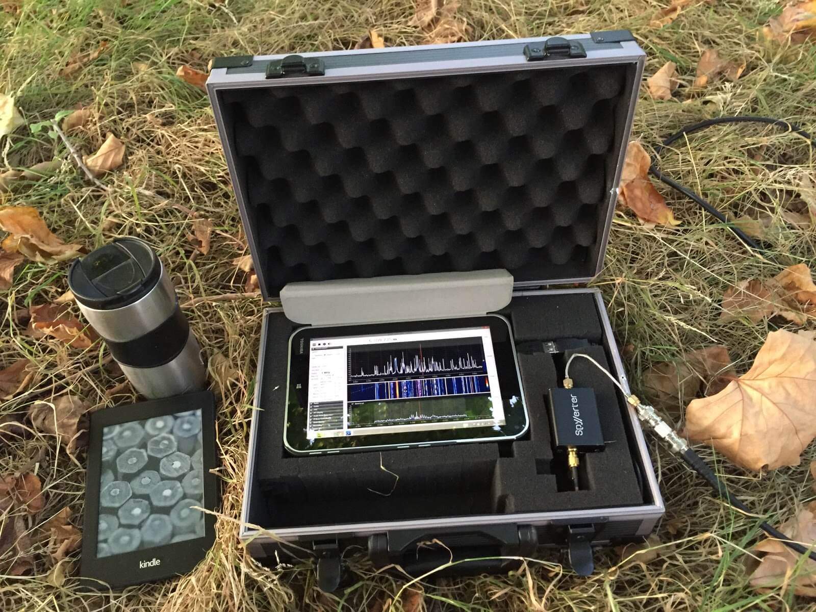
UAF plans to activate HAARP again at the end of Feburary, so it seems that it would be interesting to receive the waveforms with an HF capable SDR such as the RTL-SDR v3, or with an upconverter like the SpyVerter. Under some conditions the signal could propagate all over the world. It seems that the researchers are also interested in reception reports from listeners and they plan to post updates closer to the dates of transmission. The full press release reads:
The University of Alaska Fairbanks Geophysical Institute is planning its first research campaign at the High Frequency Active Auroral Research Program facility in Gakona.
The High Frequency Active Auroral Research Program facility near Gakona includes a 40-acre grid of towers to conduct research on the ionosphere. The facility was built and operated by the U.S. Air Force until August 2015, when ownership was transferred to UAF’s Geophysical Institute.
At the end of February, scientists will use the HAARP research instrument to conduct multiple experiments, including a study of atmospheric effects on satellite-to-ground communications, optical measurements of artificial airglow and over-the-horizon radar experiments.
Members of the public can follow one of the experiments in real time. Chris Fallen, assistant research professor in space physics, will be conducting National Science Foundation-funded research to create an “artificial aurora” that can be photographed with a sensitive camera. Observers throughout Alaska will have an opportunity to photograph the phenomenon, which is sometimes created over HAARP during certain types of transmissions.
Under the right conditions, people can also listen to HAARP radio transmissions from virtually anywhere in the world using an inexpensive shortwave radio. Exact frequencies of the transmission will not be known until shortly before the experiment begins, so follow @UAFGI on Twitter for an announcement.
For more details on the dates and times of Fallen’s experiments, as well as information on how to observe, visit https://sites.google.com/alaska.edu/gakonahaarpoon/. Information is also available at the HAARP website, the UAF http://gi.alaska.edu/haarp-0 and the official UAF HAARP Facebook page, https://www.facebook.com/UAFHAARP/.
Operation of the HAARP research facility, including the world’s most capable high-power, high-frequency transmitter for study of the ionosphere, was transferred from the U.S. Air Force to UAF in August 2015.
On their Google sites page they write how to participate:
Anybody who wants to participate and follow HAARP experiments should follow the official and unofficial announcements linked at the top of this page. There are two main ways to participate in the campaign: by listening to the radio transmissions from HAARP itself or by photographing artificial auroras created by HAARP. Amateur (Ham) radio operators can also use temporary ionosphere irregularities created by HAARP to open new propagation modes for their own transmissions.
A shortwave radio and knowledge of the time and frequency of the HAARP transmissions provides opportunities to “listen in” since the radio wave energy often (but not always) propagates very large distances, sometimes worldwide! Shortwave radios capable of receiving frequencies in the same range that HAARP can transmit, between approximately 2.7 and 10 MHz (2700 and 10,000 kHz) allow anyone to hear HAARP transmissions provided long-distance radio propagation conditions are sufficient and the radio is tuned to one of the frequencies where HAARP is transmitting. Ham radio operators also have an opportunity to reflect (or “bounce”) their own transmissions, typically in the HF, VHF or UHF bands, off ionosphere irregularities created above HAARP during high-power experiments. This creates propagation modes that would normally only be possible during certain space weather events such as aurora.
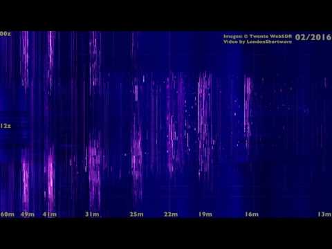
The video below shows one of the last scheduled HAARP transmissions from when it was still under the control of the US Air Force.
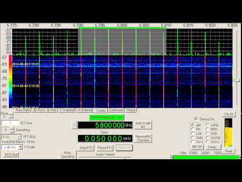
![[Fast] Visualising shortwave band activity throughout the year](https://www.rtl-sdr.com/wp-content/plugins/wp-youtube-lyte/lyteCache.php?origThumbUrl=https%3A%2F%2Fi.ytimg.com%2Fvi%2FVioW3bQsq0M%2F0.jpg)