Over on his blog RTLSDR4Everyone author Akos has uploaded a new post showing what he believes is the best possible RTL-SDR set up that you can get for under $60. Akos writes that the best combination of components is one of our RTL-SDR Blog dongles (back in stock in a couple of weeks!) with bias tee combined with an LNA4ALL low noise amplifier. The LNA4ALL is a ~$30 USD LNA based on the Minicrcuits PSA4-5043+ component and is sold by Adam 9A4QV who also sells other products such as RF filters.
Akos reminds us that the LNA4ALL can actually be bought from Adam with the bias tee enabled already which saves you from the difficulty of needing to source the required inductor and perform surface mount soldering. The post also explains why you might want to use an LNA in the first place and how to enable the bias tee on our RTL-SDR.com dongles.
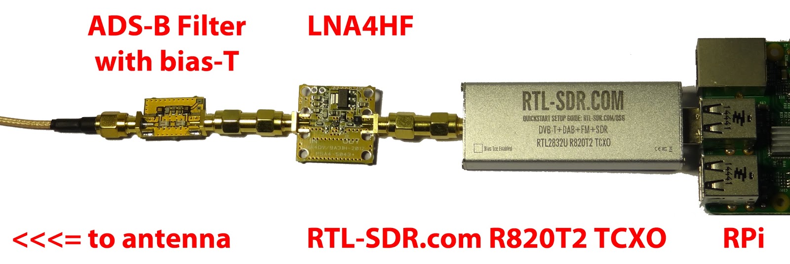
RTL-SDR.com dongle + an LNA4ALL powered with the bias tee
Recently Marek Sebera of ITDS Consulting wrote in to let us know about two new TETRA decoders that they have released. TETRA is a trunked radio communications system that stands for “Terrestrial Trunked Radio”. It is used heavily in many parts of the world, except for the USA.
The first piece of software released is called TETRA Listener and is from the Brmlab hackerspace in Prague. They write that Tetra-Listener is a new program (based on osmo-tetra) that can decode unencrypted voice and data traffic. They also write that it is very easy to set up and install since it uses Vagrant, which is a system that can be used to automatically set up a VMWare or VirtualBox Virtual Machine that has everything set up and ready to go. The instructions for using the software can then be found in the readme of the main tetra-listener page on GitHub.
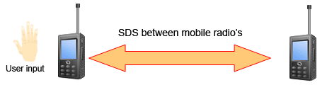
The second software they have written is what they believe is the world’s first open source TETRA Multiframe SDS decoder. SDS stands for short data service and is the TETRA equivalent to SMS text messages used on a GSM network. They write that their solution can assemble long multiframe SDS messages.
Previously we showed how unencrypted TETRA messages could be listened to using telive in our tutorial. It is good to see alternative solutions now coming out, and in the future we hope to test this new software out.
JAERO is a program by Jonti that was released late last year which allows us to use a SDR such as an RTL-SDR to receive L-band and C-Band AERO messages. AERO is essentially the satellite based version of ACARS, and the L-band signals contains short ground to air messages with things like weather reports and flight plans intended to be transmitted to aircraft. The C-band signals are the air to ground portion of AERO and more difficult to receive as they require an LNB and large dish. However they are much more interesting as they contain flight position data, like ADS-B.
If you enjoy JAERO, please remember consider donating to Jonti.
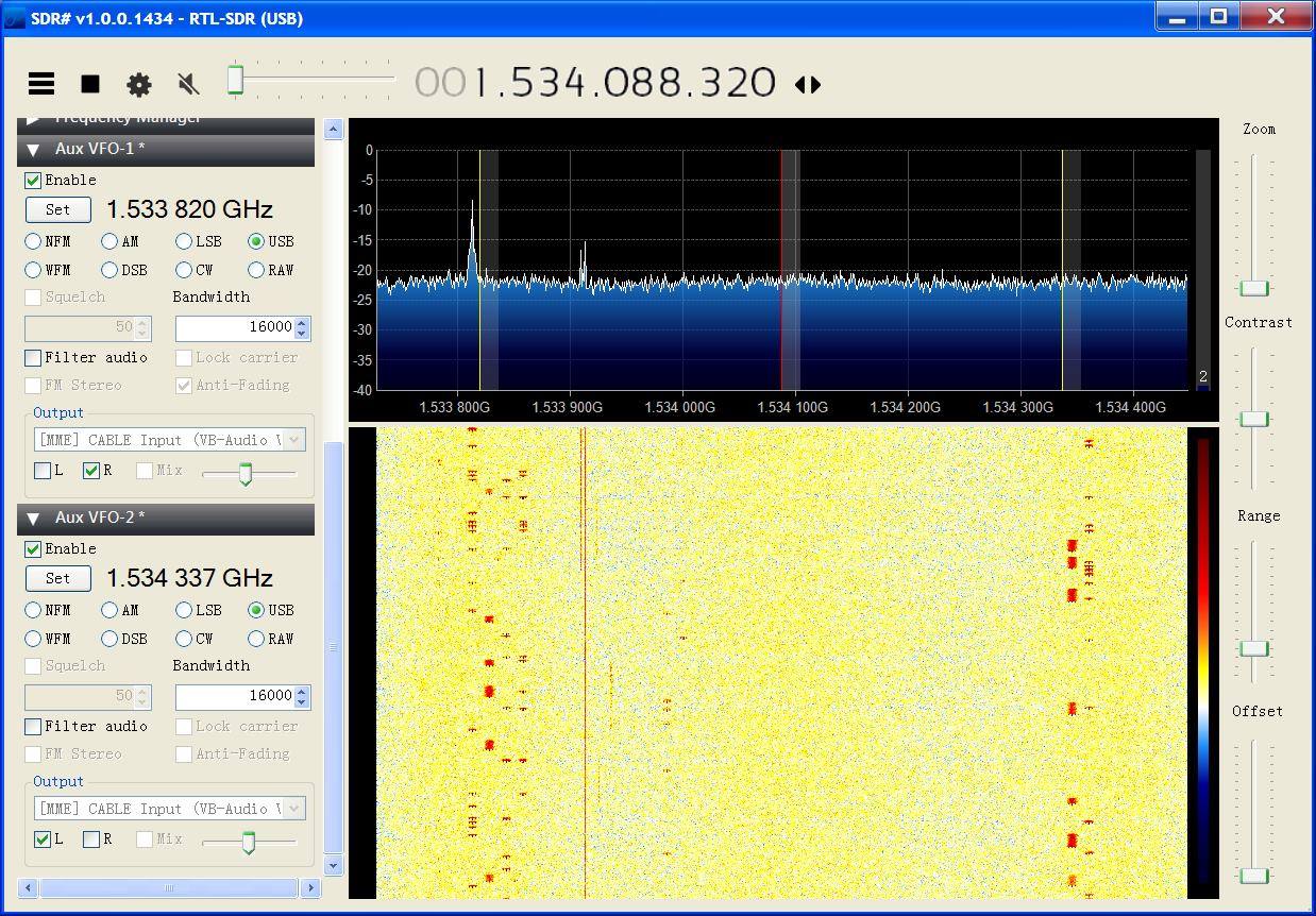
Plotting flight positions that are out of regular ADS-B range. Demodulated from C-Band AERO signals with JAERO.Monitoring two C-Band channels in SDR# with the AUX VFO plugin.
Over on the RTLSDR4Everyone blog author Akos has uploaded two new posts. In the first post he discusses his opinion on the recently announced FlightAware ADS-B Optimized ProStick, which is an RTL-SDR with an 1090 MHz optimized LNA built into the front end. He writes that he believes that the claimed 30% increase is not possible with the ProStick as his own tests using an LNA4ALL at the front end only showed a 10% increase in range at most. In his post he also shows that the updated Nooelec R820T2 stick comes with a suction cup holder for it’s supplied antenna.
To add to his post, while we haven’t received the ProStick unit we bought for review yet we believe that the ProStick will improve ADS-B reception a certain amount in some situations, especially for those using the stick in such a way where it is placed right at the antenna, or with a small desktop style antenna with little coax, both with an appropriate ADS-B filter used. However, as Akos also suggests in his post we believe that the superior solution is an external type LNA, like the LNA4ALL.
The rtl_power program allows you to use the RTL-SDR to perform a power scan over an arbitrarily large portion of the frequency spectrum (within the RTL-SDR’s supported frequency range) by hopping over ~2 MHz swaths of bandwidth. The updated rtl_power_fftw software was originally written by Klemen Blokar and Andrej Lajovic and is an update over the regular rtl_power program. It uses a faster FFT processing algorithm and has several other enhancements that make it more useful for radio astronomy purposes.
-e param for session duration this allows to specify the recording duration in sec, mins… etc just like it was possible with rtl-power
-q flag to limit verbosity this will allow the various printouts to happen only the first time and not on every scan
-m param to produce binary matrix output and separate metadata file this will get a file name (no extension) and use it to store the power values in binary format within a .bin file + a metadata text file with .met extension
Summary of my requirements:
I wanted to leverage the ability of rtl-power-fftw to specify N average values to integrate for less than 1 second when needed. Plus running multi-MHz scans and storing for several minutes.
I wanted to use a binary format instead of the .csv one in order to obtain the smallest possible size since I’m logging all the night long (CSV’s blank delimiters and decimal dots were wasting my precious microSD space)
keep high the precision on decimal digits saving float values (could be important for other usages)
obtain a complete stream of binary values representing all the bins for each scan, one scan after the other, in a matrix like organization
…that would allow me to plot the waterfall extremely fast with gnuplot
…and then add specific annotations and file properties/metadata in a more convenient way using python
Example rtl_power_fftw output: A scan of Jupiter’s radio emissions.
The FlightAware team have today announced the release of the "ProStick", an RTL-SDR dongle that they write has been modified for improved ADS-B reception. The new FlightAware RTL-SDR's main defining feature is that it comes with a built in low noise amplifier (LNA) on the front end. The built in LNA is optimized for the ADS-B frequency of 1090 MHz and has 19 dB of gain with a 0.4 dB noise figure and an OIP3 of +39dB. They claim that the new unit will give a 20-100% performance boost in terms of range for Mode S reception when compared to a standard RTL-SDR.
As the increased gain and amplifier non-linearities can cause overload and intermodulation to more easily occur, the FlightAware team stresses that you must use the new device with a 1090 MHz filter, such as their FlightAware filter. In a previous post we reviewed the FlightAware filter and antenna and found that they performed very well and are great value for money.
So far we haven't seen any circuit photos or news about which LNA chip has been used, but we intend buy a unit and do a review when it arrives.
One criticism about this unit that we can already see is that it should be understood that good RF design teaches us to always place the LNA as close to the antenna as possible to overcome cable loss and keep the noise figure low. Placing the LNA at the antenna vs at the receiver makes a huge difference in performance, depending on how long and lossy your coax cable run is. Furthermore, integrating an LNA into the receiver ruins the system for optimal performance with an LNA placed by the antenna due to the reduced linearity caused by the additional internal LNA. The post at http://ava.upuaut.net/?p=836 explains optimal LNA placement very well. We think that perhaps selling an external LNA and bias tee module would have been a significantly better idea to optimize ADS-B reception. However, the additional LNA should help to reduce the noise figure of the dongle by a few dBs which will result in improved ADS-B reception as long as signal saturation does not occur.
The new FlightAware ADS-B optimized RTL-SDR.The new FlightAware dongle running on a PiAware Raspberry Pi system (actual unit uses SMA).
According to various reports the Russian Meteor M-N2 satellite appears to be active again once more. The Meteor M N-2 is a polar orbiting Russian weather satellite that was launched in July 2014. It transmits with the LRPT protocol which allows us to receive weather satellite images with an RTL-SDR that are of a much higher resolution than the NOAA APT satellites.
Unfortunately late last year Meteor M N-2 had some problems and LRPT transmissions were turned off for the time being. During this downtime the Russian space agency switched the LRPT transmitter on the older Meteor M N-1 satellite back on, even though the satellite was tumbling in orbit. Currently people are not reporting any signal from Meteor M N-1, so this may have been turned off, perhaps temporarily.
Now however, it seems that Meteor M N-2 has been switched back on again and various people have already successfully received its signal. If you want to receive these Meteor M N-2 weather images with an RTL-SDR dongle or other SDR then you can view the tutorial written by Happysat here.
For accurate frequency tuning even amongst large temperature in an SDR, a Temperature Compensated Crystal Oscillator (TCXO) should be used as the main oscillator. Standard RTL-SDR dongles used a frequency of 28.8 MHz and do not come with a TCXO, but for some time now we have been selling our own branded dongles that come with a TCXO built in (out of stock at the moment sorry – back in the first half of April!). If you have an older or other dongle that does not have a TCXO it can be an interesting exercise to hack one in yourself. The biggest problem though, is that 28.8MHz TCXO oscillators are not commonly found for sale in low quantities.
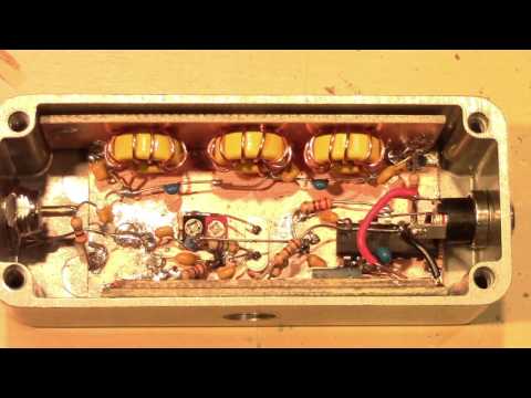
Over on YouTube user devttys0 (Craig) has uploaded a video that thoroughly explains the theory behind creating a home brew 28.8 MHz TCXO out of a standard non-temperature controlled 19.2 MHz oscillator. The build involves halving the frequency, and then filtering and using the third harmonic as the clock signal (19.2/2 * 3 = 28.8 MHz), as well as creating the temperature compensation circuitry.
If you wanted to make something a little easier to build then we recommend looking at our previous post which shows how an experimenter used an SI5351A voltage controlled oscillator on the RTL-SDR.