Tagged: rtl2832

Building a 28.8 MHz TCXO for the RTL-SDR

For accurate frequency tuning even amongst large temperature in an SDR, a Temperature Compensated Crystal Oscillator (TCXO) should be used as the main oscillator. Standard RTL-SDR dongles used a frequency of 28.8 MHz and do not come with a TCXO, but for some time now we have been selling our own branded dongles that come with a TCXO built in (out of stock at the moment sorry – back in the first half of April!). If you have an older or other dongle that does not have a TCXO it can be an interesting exercise to hack one in yourself. The biggest problem though, is that 28.8MHz TCXO oscillators are not commonly found for sale in low quantities.

Over on YouTube user devttys0 (Craig) has uploaded a video that thoroughly explains the theory behind creating a home brew 28.8 MHz TCXO out of a standard non-temperature controlled 19.2 MHz oscillator. The build involves halving the frequency, and then filtering and using the third harmonic as the clock signal (19.2/2 * 3 = 28.8 MHz), as well as creating the temperature compensation circuitry.

On his blog Craig has also uploaded schematics and a frequency temperature curve he measured from his home brew TCXO.

If you wanted to make something a little easier to build then we recommend looking at our previous post which shows how an experimenter used an SI5351A voltage controlled oscillator on the RTL-SDR.

A GNU Radio Based ISDB-T and RTL-SDR Compatible 1Seg Decoder

In most parts of the world the DVB-T standard is used to air digital HDTV. In the USA the ATSC standard is used, and in China DTMB is used instead. In other countries such as Brazil, Peru, Argentina, Chile, Honduras, Venezuela, Ecuador, Costa Rica, Paraguay, Philippines, Bolivia, Nicaragua and Uruguay a third standard called “ISDB-T International” is used which is based on the Japanese ISDB-T standard. 

Digital broadcast standards used in each country.

Recently a team from Uruguay has been working on creating a ISDB-T receiver in GNU Radio. With this decoder ISDB-T signals can be received with a wide bandwidth SDR (needs to be 6MHz or larger) and then decoded into a video file. Because ISDB-T is so similar to DVB-T they have based much of their code on gr-dvbt which is a GNU Radio based DVB-T decoder.

In addition to the ISDB-T decoder, they have also implemented a 1-seg decoder. 1-seg is a mobile HDTV service that exists in Japan, Argentina, Brazil, Chile, Uruguay and Peru. It runs on the ISDB-T system, and is called “1-seg” because it’s data occupies 1-segment of the 13-segment based ISDB-T bandwidth. It is used in small mobile TV receivers, many of which are now built directly into mobile phones sold in countries that use ISDB-T. Due to it’s much lower bandwidth requirement the 1-seg decoder can be used with an RTL-SDR dongle, and has already been tested to work.

A typical 1-seg capable Japanese mobile phone receiving digital mobile TV.
A typical 1-seg capable Japanese mobile phone receiving digital mobile TV. With the GNU Radio 1-seg decoder these transmissions can be received with an RTL-SDR.

Inspectrum: A New Tool for Analysing Captured Signals

Inspectrum is a Linux and OSX based tool that can be used for analysing captured signals. It is compatible with the IQ files generated from SDRs, such as the RTL-SDR or HackRF.

Over on YouTube user Mike has uploaded a video that demo’s the latest version of Inspectrum. He shows how the tool can be used to quickly browse the waveforms in a captured signal and how it can be used to determine various digital binary signal properties through an overlay that can be dragged to match the bit frequency of the captured signal.

This program looks like it is shaping up to be a very useful tool for those interested in reverse engineering digital signals. The Inspectrum code and installation procedure can be found at https://github.com/miek/inspectrum.

inspectrum tuner demo

RTLSDR4Everyone: Raspberry Pi guide & choosing your first dongle

Over on his blog rtlsdr4everyone author Akos has recently uploaded three new posts. The first post is about the Raspberry Pi minicomputer and the post discusses the merits of using the Raspberry Pi with an RTL-SDR dongle. The second post provides information to help people new to RTL-SDR choose their first dongle, and weighs up options between dongles that cost $10, $20, $25, $35 and $50 dollars. Finally, the third post compares two dongles on HF performance.

Raspberry Pi3 and RTL-SDR dongles.

Creating a FSK SSDV data system for High Altitude Balloons

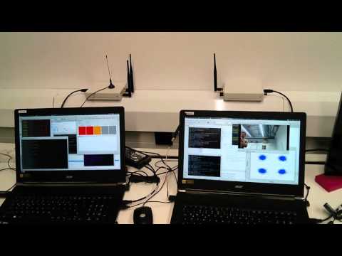
David and Mark are building a 115 kbit/s FSK SSDV (slow scan digital video) data system for high altitude balloons. In their system, on the balloon transmit side they use a Raspberry Pi, Raspberry Pi camera and a RFM22B wireless transceiver modulator board to transmit the SSDV FSK signal. On the receive side they use an RTL-SDR dongle, low noise preamplifier and a GNU Radio program to demodulate the SSDV images. The first video below demonstrates the hardware and GNU Radio program and shows them receiving the SSDV signal. In the second video they demonstrate that the images can be received at low signal levels (-106dBm) as well, by heavily attenuating the signal.

115.2kbaud FSK Modem Test

115.387kbaud FSK Modem Test - Part 2

If you are interested, all their code for the SSDV system has been uploaded to https://github.com/projecthorus/HorusHighSpeed.

While testing the RTL-SDR for use in this system they also measured the noise figure of an R820T RTL-SDR dongle. The noise figure at maximum gain comes out at around 5.6 dB. By adding a low noise amplifier they reduce the measured noise figure down to 2 dB.

Testing the attenuated SSDV signal reception with an RTL-SDR.

Building a simple NOAA APT Antenna out of an Umbrella

In order to optimally receive NOAA weather satellite images a special satellite antenna tuned for 137 MHz should to be built. Generally either a QFH or turnstile antenna is recommended as these receive signals coming from the sky very well. If you are interested in receiving weather satellite images from NOAA satellites with an RTL-SDR dongle then we have a tutorial available here.

While QFH and turnstile antennas are not difficult or expensive to build, they still do require a small amount of electrical and construction skills. Over on YouTube user Wanderlinse shows us a possible alternative NOAA antenna that is simply made out of an old umbrella (the video is narrated in German, but it is easy to understand from the visuals). He uses a short BNC cable with crocodile clips, and connects one clip to the spines of the umbrella, and the other to the central metal shaft. For some reason this seems to create a good antenna that receives NOAA APT signals very well. To prevent wind issues he also cuts out some holes in the umbrella fabric.

Wanderlinse also shows that he can receive other signals with this umbrella antenna too, such as long wave, medium wave, shortwave, aircraft radio and ham radio.

Regenschirm Antenne NOAA APT Umbrella Antenna (quick n dirty)

Finding GPS Signals from within the Noise Floor with an RTL-SDR

If you were to try to simply spot a GPS signal at 1.575 GHz in the spectrum on a waterfall in a program like SDR# you would probably fail to see anything. This is because GPS signals are very weak, and operate below the thermal noise floor. Only through clever processing algorithms can the actual signal be recovered.

Previously GPS and SDR enthusiast “e.p.” showed us on his blog how to use an RTL-SDR and the GNSS-SDRLIB and RTKLIB software to receive GPS and get a position lock.

Now more recently e.p. has uploaded a post that explains a bit about how GPS signals are actually detected from below the noise floor. In his post he uses GPS data collected by his RTL-SDR dongle, and a fairly simple GNU Radio program consisting of a Fast AutoCorrelation Sink block.

With real data passed through the fast autocorrelation block he is able to observe GPS signal peaks that occur every millisecond. E.p. explains the reason for this:

Why every millisecond? The coarse/acquisition code for GPS (C/A) has a period of 1023 chips which are transmitted at a rate of 1.023 MBit/s. This results in period of 1 millisecond. BAM!

In a later post e.p. has also uploaded some sample GPS data collected with his RTL-SDR so anyone can play around with GPS decoding.

Autocorrelation of a GPS signal resulting in peaks every millisecond.

Review: FlightAware 1090 MHz ADS-B Antenna and Filter

In this post we will review the FlightAware ADS-B Antenna and their 1090 MHz band pass filter. The FlightAware ADS-B antenna is claimed to have 5.5 dBi of gain, a rugged weatherproof radome and N-type female connector. It costs $44.95 USD on Amazon for US customers and $54.95 USD on eBay for international customers (plus shipping). They write that they are selling this antenna at cost in order to improve FlightAware coverage.

The FlightAware ADS-B filter is a bandpass filter with a pass range of 980MHz - 1150MHz, ~1.5dB insertion loss and more than 40dB attenuation of unwanted frequencies. It costs $19.95 USD on Amazon for US customers and $24.99 USD on eBay for international customers (plus shipping). Generally it is much cheaper than other ADS-B filter options on the market.

FlightAware.com is a company that specializes in aggregating ADS-B data from contributors around the world. People can contribute by using the FlightAware official hardware, or with a simple SDR, like an RTL-SDR dongle. They display the data on their website as it can be used to help track flight arrival times. A similar company is flightradar24.com.

If you are interested in getting started with ADS-B reception with your RTL-SDR then we have a tutorial here.

FlightAware ADS-B Antenna

The FlightAware antenna is about 64cm in length and about 2cm in diameter. It uses an N female connector and comes included with mounting brackets and U-bolts. It is painted olive green.

In the photo below we compare the size of the antenna against a reference monopole antenna, an RTL-SDR dongle and the FlightAware ADS-B filter. The antenna appears to be very solidly built and of a high quality finish. The antenna is wareproofed with some silicon caulking used around the seams of the endcaps.

Size comparison
Size comparison

The FlightAware ADS-B antenna is a collinear type antenna. Collinear antennas are omnidirectional (receives equally from all directions) and have a higher gain compared to most other omnidirectional antennas, but their radiation pattern is flattened and directed more towards the horizon. This is a good thing for receiving planes that are far away as they will be at lower elevations, but aircraft at higher elevations relative to your antenna may be received poorer. Although, it is likely that any aircraft at high elevations to your position will be closer to you anyway, and thus have a stronger signal making the reduced gain at higher elevations less important. Judging by it's ~60cm length and it's specified gain of 5.5dBi, the FlightAware antenna is likely to be a 4 element collinear.

A 4 element collinear generally has positive gain from 0 - 20 degrees of elevation, whereas a simple dipole or ground plane may have positive gain from between 0 - 40 degrees of elevation. A typical commercial jet flys at about 10km. At a distance of 100km this jet would be at a 5.7 degree elevation, and at 10km 45 degrees. Smaller aircraft fly at about 3km maximum, and at 100km would have an elevation of 1.7 degrees, and at 10km 16.7 degrees, so the collinear covers most cases.

A reader wrote in to us to let us know that the internals of the FlightAware antenna had actually previously been posted in an old thread on their forums. From the image it looks like the antenna may be a sleeved dipole + whip + impedance matching design, or something similar. This design is somewhat of a collinear design thanks to the additional whip which also gives a flatter radiation pattern with more gain direction out towards the horizon. These antennas are omnidirectional (they receive equally from all directions) and have a higher gain compared to most other omnidirectional antennas, but their radiation pattern is flattened and directed more towards the horizon. This is a good thing for receiving planes that are far away as they will be at lower elevations, but aircraft at higher elevations relative to your antenna may be received poorer. Although, it is likely that any aircraft at high elevations to your position will be closer to you anyway, and thus have a stronger signal making the reduced gain at higher elevations less important.

The internals of the FlightAware antenna.

If you live in a valley, or have multiple obstacles such as trees or buildings blocking your view of the horizon then the higher gain design may work worse than a dipole/quarter wave ground plane/folded monopole type antenna. In this situation you'd mainly only be able to receive ADS-B signals from higher elevations, so an antenna with a less flat radiation pattern would work better. See the end of this post for some example radiation pattern diagrams.

Continue reading