Category: Applications

A Guide to Listening to CB Radio with an RTL-SDR Dongle

In the June edition of The Spectrum Monitor, SDR enthusiast and ham Mario Filippi N2HUN published an article titled “Your New CB ‘Good Buddy’, the SDR Dongle”. While the CB radio heyday is well and truly over, Mario discusses how an RTL-SDR dongle can be used to have some fun listening to CB without needing to go out and buy a full CB radio. If you don’t know what CB radio is, Mario explains what it is, and its rise and fall in these excerpts:

In the mid-1970’s an early form of social media was sweeping across the country known as CB (Citizens Band) radio. In those years the FCC required CB radio operators to obtain a license, easily gotten by filling out FCC form 505, paying the fee ($20 or $4 depending on what year you applied), and waiting very patiently, usually two to three months for your license to arrive by mail with your call sign.

The concept of wirelessly communicating with others without studying for a licensing exam somehow caught on and was embraced by the American public. As a result, in the mid-70’s CB sets started flying off the shelves by the millions to appease this new insatiable appetite of Americans to talk over the air with their “good buddies” (CB slang for friend). Other major factors played into the oncoming tsunami of CB’ers: gasoline was getting scarce as a result of the recent oil embargo, prices were quickly escalating at the pump, and the Interstate Highway maximum speed was lowered to 55 MPH prompting drivers with heavy feet to communicate the whereabouts of radar-enabled local police (CB slang: Smokies or Smokey Bears) or the cheapest place to fill up. In addition, traffic information such as road conditions, accidents, speed traps and the best greasy spoon location was now available to the commuting public by simply turning on the CB radio and tuning to the trucker’s Channel 19, the epicenter for the latest road-related poop.

By the late ‘70’s there were so many CB’ers congregating on the air causing non-stop channel chatter and ignoring FCC regulations (C.F.R. Part 95) that Uncle Charlie (CB slang for the FCC) eventually dropped the license requirement. The American public now ruled the airways with expanded 40 channel radios and pandemonium. Call signs were replaced by nicknames or “handles” and everyone prided themselves with their own, unique self-descriptive moniker when “ratchet-jawing” (slang for talking a lot) on their CB radio. But when the early 80’s rolled around the public’s fleeting romance with this mode of communication had dwindled markedly and only the diehards remained on the air in happy solitude.

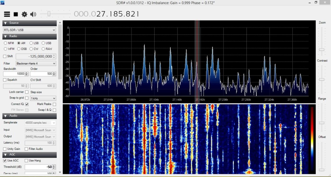
The article goes over several points which may be useful to those who did not play around on CB back in its popular days. He explains how CB radio exists on frequencies between 26.965 MHz to 27.115 MHz and how you should use an appropriate (large) CB antenna, such as an 43 foot S9 vertical antenna. He also notes how CB radio conditions can be affected by ionospheric conditions, and how on a good day (CB is usually open during the day as opposed to the night for the lower frequencies) you can actually receive CB radio from all over the world including Europe, the Caribbean and the US. 

As the article is a part of The Spectrum Monitor magazine it is not free to read, but each monthly edition only costs $3 USD, and comes with multiple articles from other authors too, which makes it quite a good bargain read every month. You can find the June edition at http://www.thespectrummonitor.com/june2015tsm.aspx.

CB Radio coming in with an RTL-SDR and CB antenna on SDRSharp.

Decoding a Garage Door Opener with an RTL-SDR

After listening to dock workers with his RTL-SDR for a few days, RTL-SDR.com reader Eoin decided that he wanted to try a more practical experiment. He decided to see if he could reverse engineering the wireless protocol on his garage door opener. Upon opening his remote he discovered a bunch of DIP switches, which are presumably used to program the remote to a particular garage door. Eoin’s next step was to determine at what frequency the garage door opener was transmitting at. He made an assumption that it would be in the 433 MHz unlicenced ISM band as this is where many handheld remotes transmit at. He was right, and found the signal.

The garage door remote showing the DIP switches.

His next step was then to record the signal audio in Audacity. From the audio waveform he could see a square wave which looked just like binary bits. By manually eyballing the waveform and translating the high/low squarewave into bits he was able to get the binary data. He then confirmed this data with the dipswitch positions and discovered that a 010 binary code matched with the UP position on the dip switch and 011 matched with the DOWN position.

Having decoded the signal manually fairly easily, Eoin decided his next challenge would be to automate the whole decoding in GNU Radio. In the end he was successful and managed to create a program that automatically determines the position of the DIP switches from the signal. His post goes into detail about his algorithm and GNU Radio program.

Showing the decoded DIP switch positions from his GNU Radio program.

Updates on using an RTL-SDR for GPS on a High Powered Rocket

Back in April we posted about Philip Hahn and Paul Breed’s experiments to use an RTL-SDR for GPS logging on their high powered small rockets. As GPS is owned by the US military, a standard GPS module cannot be used on a rocket like this, as they are designed to fail if the GPS device breaches the COCOM limit, which is when it calculates that it is moving faster than 1,900 kmph/1,200 mph and/or higher than 18,000 m/59,000 ft. The idea is that this makes it harder for GPS to be used in non-USA or home made intercontinental missiles. As SDR GPS decoders are usually programmed in open source software, there is no need for the programmers to add in these artificial limits.

In their last tests they managed to gather lots of GPS data with an RTL-SDR, but were only able to decode a small amount of it with the GNSS-SDR software. In this post Philip discovers a flaw in the way the GNSS-SDR performs acquisition and retracking that GNSS-SDR decodes in such a way that makes it difficult to obtain a location solution with noisy high-acceleration data. By using a different GPS implementation coded in MATLAB, he was able to get decoded GPS data from almost the entire ascent up until the parachutes deploy. Once the parachutes deploy the GPS has a tough time keeping a lock as it sways around. His post clearly explains the differences in the way the code is implemented in GNSS-SDR and in the MATLAB solution and shows why the GNSS-SDR implementation may not be suitable for high powered rockets.

In addition, they write that while the flight was just under the artificial COCOM GPS fail limits for speed and height, the commercial GPS solution they also had on board failed to collect data for most of the flight too. With the raw GPS data from the RTL-SDR + some smart processing of it, they were able to decode GPS data where the commercial solution failed.

GPS data acquired from the RTL-SDR on the rocket.
GPS data acquired from the RTL-SDR on the rocket (blue line shows solution from MATLAB code, yellow shows GNSS-SDR solution, and red shows commercial GPS receiver solution).

LuaRadio: New Flowgraph Based Digital Signal Processing Framework for SDR

LuaRadio is a new Digital Signal Processing (DSP) framework for software defined radios such as the RTL-SDR. It is similar to GNU Radio in that the flowgraph is composed of graphical blocks that can be visually connected to one another in an editor. However compared to GNURadio it aims to be very lightweight in terms of disk space used (1 MB footprint) and the number of dependencies required (zero dependencies required unless you need real time highly optimized libraries). It is also written purely in the Lua programming language. The authors of LuaRadio write “LuaRadio is more inclined towards scripting and prototyping than GNU Radio, and emphasizes fast block development.”

On their website there are already several example application flowgraphs uploaded, such as decoders for WBFM Mono/Stereo, NBFM, AX.25, POCSAG, RDS, AM and SSB. Looking and building such flowgraphs is extremely helpful for learning DSP, and DSP languages like this are excellent for prototyping new signal decoders. In addition, if you are new to SDR they also have a very useful page that explains basic SDR and radio concepts.

A LuaRadio based POCSAG decoder flowgraph.

Building an ESP8266 Based Plane Spotter with an RTL-SDR Feeder

Living near Zurich airport, Daniel Eichorn wanted an easy way to show his house guests what planes are flying near him. Usually he opens up his Flightradar24 app on his phone, but he wanted a more permanent always on display. To do this Daniel has built an ESP8266 based OLED display which automatically displays the ADS-B flight information of aircraft outside his window. The ESP8266 is a very cheap and highly popular WiFi module which can give a microcontroller access to WiFi networks.

Daniel feeds his locally received ADS-B data to adsbexchange.com using a Raspberry Pi and RTL-SDR. While actually feeding ADS-B data with an RTL-SDR is not required to make the ESP8266 module work, this step ensures that he has good local coverage of his area. The ESP8266 module then queries the adsbexchange.com database via WiFi for information about planes in his area and displays the information on the OLED screen.

In previous posts we also showed how the ESP8266 could be used to transmit data like NTSC TV in a similar way to Rpitx.

ESP8266 + OLED screen displaying ADS-B data.

An RTL-SDR to RTL-SDR QSO with RTL-TRX: Transmit RTTY with the RTL-SDR

Back in 2014 oh2ftg discovered that the RTL-SDR could actually be used to transmit data by modulating leakage from its internal local oscillator. Now it seems that tejeez and oh2ftg have released a new program that makes transmitting with the RTL-SDR easy. The program is called rtl-trx. It runs on Linux and allows you to to transmit RTTY or a simple beacon with the RTL-SDR. The software is available on GitHub at https://github.com/tejeez/rtl-trx. About how it works, the readme says:

Local oscillator leakage from an RTL-SDR dongle can be used as a very low power FSK transmitter. This program transmits RTTY and also makes it easy to use the same dongle to receive RTTY in between transmissions. The goal is to make it possible to have a two-way QSO between two dongles.

Over on YouTube oh2ftg has also uploaded a video that demonstrates the software in action by doing a 1270 MHz RTTY QSO between two modified RTL-SDR dongles. He uses fldigi to decode the RTTY signal and the signal is sent with the following settings: 425 Carrier shift, 45.45 Baud rate, 5 Bits per character, none Parity, 2 Stop bits. 

This previous post shows the hardware modification that can be done to improve the output power. Again, as with the Raspberry Pi transmitters, the output power is very low and probably won’t cause any trouble, but still please do take care if you intend on actually transmitting anything as the output spectrum is probably not very clean.

RTL2RTL QSO! on 1270MHz

Sniffing ANT-FS with an RTL-SDR and MMDS Downconverter in Pothos

ANT-FS is a wireless file transfer protocol that is designed specifically for transferring files wireless between two devices. It is designed for ultra low power devices and typically runs on devices operated by a coin sized battery. It is commonly used in applications like fitness tracker devices, which store data to later be downloaded to a PC.

Over on YouTube user sghctoma has uploaded a video showing a teaser of him receiving and decoding ANT-FS packets with blocks developed for the POTHOS graphical language. As ANT-FS is usually transmitted at 2.4 GHz, he had to use a MMDS downconverter which allowed his RTL-SDR to receive the packets. Sghctoma writes that the video is simply a teaser, and that a live demo with real deivce, and the full code + details will be released during his talk at DEFCON titled “Help, I’ve got ANTs!!!”.

ANT-FS sniffing with RTL-SDR, an MMDS downconverter and Pothosware

Building a Quad RTL-SDR Receiver for Radio Astronomy

Amateur radio astronomer Peter W East has recently uploaded a new document to his website. The document details how he built a quad RTL-SDR based receiver for his radio astronomy experiments in interferometry and wide-band pulsar detection (pdf – NOTE: Link Removed. Please see his website for a direct link to the pdf “Quad RTL Receiver for Pulsar Detection”. High traffic from this post and elsewhere has made the document go offline several times). Interferometry is a technique which uses multiple smaller radio dishes spaced some distance apart to essentially get the same resolution a much larger dish. Pulsars are rapidly rotating neutron stars which emit radio waves, and the strongest ones can be observed by amateur radio telescopes and a receiver like the RTL-SDR.

The Quad receiver has four RTL-SDR’s all driven by a single TCXO, mounted inside an aluminum case with fans for air cooling. He also uses a 74HC04 hex inverter to act as a buffer for the 0.5 PPM TCXO that he uses. This ensures that the TCXO signal is strong enough to drive all four RTL-SDRs.

The Quad RTL-SDR with air cooling.

Whilst all the clocks are all synced to a single master clock, synchronisation between the RTL-SDR’s is still difficult to achieve because of jitter introduced by the operating system. To solve this he introduces a noise source and a switch. By switching the noise source on and off, correlation of the signal data can be achieved in post processing.

Noise Source and Switch Calibration Unit.
How correlation with the pulsed noise source works.

In the document Peter shows in detail how the system is constructed, and how it all works, as well as showing some interferometry results. The system uses custom software that he developed and this is all explained in the document as well.