In our last postAdam Alicajic showed us on YouTube how to determine the frequency response of an RF filter using just a wideband noise source an LNA and an RTL-SDR dongle.
In his latest video Adam shows how the SWR of an antenna can be measured using almost the same low cost equipment. One additional piece of hardware required to measure the SWR is a directional coupler which can be bought on Ebay for about $10 USD.
SWR stands for "standing wave ratio" and is a measure that can be used to tune an antenna for a particular frequency. The closer the SWR is to 1:1 at the designed antenna frequency, the better the antenna will receive (and transmit).
In his video Adam shows how he measures the SWR of an ADS-B antenna which he has built and is selling. His results show that the antenna has an SWR of 1:1.02 at 1090 MHz which is quite good.
DIY Characterize the antenna Retrurn Loss / SWR with the DVB-T SDR
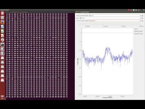
Over on YouTube RTL-SDR experimenter Adam Alicajic has uploaded a video showing how it is possible to use the RTL-SDR as a tool to measure the frequency response of an RF filter. To do this he uses a noise source circuit which produces wide band white noise connected to an LNA4ALL, connected to the RF filter and finally connected to the RTL-SDR. Then using the Touchstone spectrum analyzer software he does a 300 MHz bandwidth sweep over a section of the spectrum which shows the response of the filter.
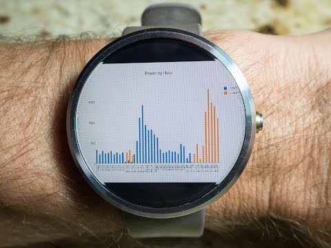
To gather the power usage data he used an RTL-SDR connected to a PC running rtlamr, which is software that can read data from ERT compatible power meters that transmit in the 900 MHz ISM band. He also uses some custom code he wrote that automatically plots the data over time and allows him to integrate it with his home automation system. In addition to his post he also uploaded a video shown below that shows his system in action.
Monitoring house power using a $20 RF RTLSDR USB stick
Over a year ago we wrote a tutorial on how to analyze GSM cellular phone signals using a RTL-SDR, a Linux computer with GNU Radio, Wireshark and a GSM decoder called Airprobe. With this combination it is possible to easily decode GSM system messages. Setting up Airprobe is can be difficult as it is unmaintained and incompatible with the new version of GNU Radio without patches.
Now a new software package called gr-gsm has been released on GitHub which seems to be a newer and improved version of Airprobe. The gr-gsm software is also much easier to install, uses the newer GNU Radio 3.7 and seems to decode the system data with much less trouble than Airprobe did. We will soon update our tutorial to use gr-gsm, but the instructions on the GitHub are already quite good. The author of gr-gsm also appears to be actively adding new features to the software as well. The video below shows gr-gsm in action.
Sniffing GSM data with gr-gsm and cheap RTL-SDR receivers
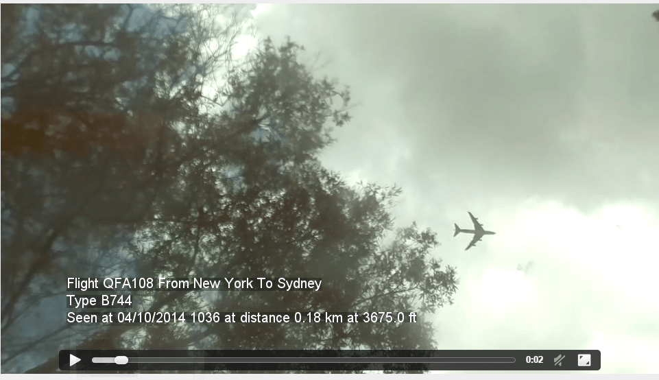
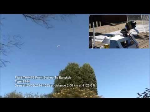
Simon’s project works by using the RTL-SDR connected to the Raspberry Pi as an ADS-B receiver. From the ADS-B signals the current coordinates of nearby aircraft can be determined. Then by using some coordinate math, the Raspberry Pi can be told to point its camera in the direction of the aircraft. As well as videoing the passing aircraft, the Raspberry Pi also overlays text on to the video showing information such as flight number, source and destination airports, aircraft type, elevation and distance and date of observation.
In addition to all that, his software also automatically uploads the recorded videos onto his website. Here you can see the latest and closest video captures his system has performed.
NOTE: There is now a plugin available for SDR# that will decode TETRA fairly easily. It is still in beta and misses a few features found in telive. Check it out in this post.
TETRA is a trunked radio communications system that stands for "Terrestrial Trunked Radio". It is used heavily in many parts of the world, except for the USA. Recently, a software program called Tetra Live Monitor (telive) was released on GitHub. This software can be used along with the (patched) Osmo-TETRA software to monitor and listen to unencrypted TETRA communications.
Below we show a tutorial on how to listen to TETRA communications using a RTL-SDR RTL2832U software defined radio. This tutorial is based heavily on the telive_doc.pdf file that is written by the author of telive and included in the telive git download. Please refer to that pdf file for further details on how the software works. We have modified their tutorial slightly to make it a little easier to understand. As this code is still under heavy development if you have trouble please check their PDF file for modifications to the procedures.
Most of this tutorial is performed in Linux and we assume that you have some decent Linux experience. We also assume you have some experience with the RTL-SDR dongle and have a decent antenna capable of picking up TETRA signals in your area. If you don't have a RTL-SDR dongle yet see our Buy RTL-SDR dongles page.
Note: As of October 2016 there is now a Windows port of the Telive decoding software available. This may be an option for you if you prefer to run in Windows. More information here.
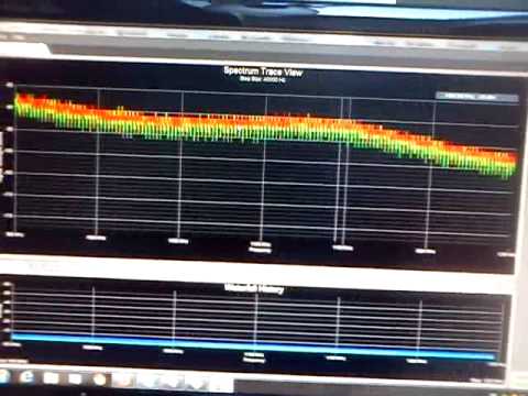
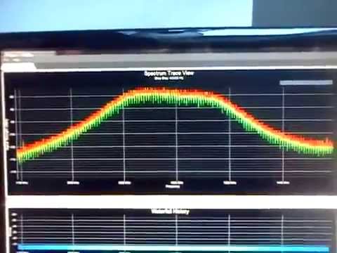
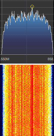
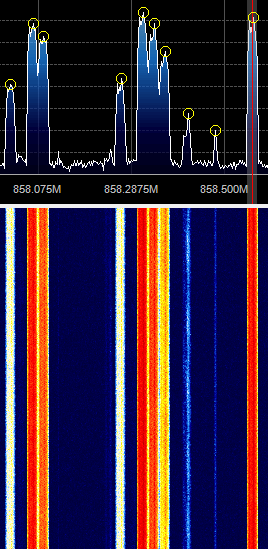
First, we will need to find some TETRA signals. The easiest way to do this is to open SDR# or another program like GQRX and look for them. TETRA signals are continuously broadcasting with a bandwidth of around 25 kHz. In most European countries they can be found at 390 - 470 MHz. In some countries they may be found around 850 MHz or 915 - 933 MHz. There may be several TETRA signals grouped in close proximity to one another. See the example images below.
A Zoomed in TETRA Signal
A Grouping of TETRA Signals Zoomed Out
An example audio clip of a TETRA signal recorded in NFM mode is shown below.
Once you have found some TETRA signals, record their frequencies. Now close SDR#, or whatever software you were using and boot into Linux. In this tutorial we use a 32-bit Ubuntu 14.04 virtual machine running on VMWare Player as our Linux system. Some of the commands may vary if you are using a different system.
Over on YouTube we’ve discovered a video from earlier in the year showing the RTL-SDR being used as a passive aircraft radar. This is different to ADS-B which is a type of active radar. A passive radar works by using a very strong radio signal from a readily available source such as a TV or FM radio transmitter and detecting the reflections from aircraft.
A RTL-SDR based passive radar system can be built by connecting two RTL-SDR dongles to a single clock source and by using two directional antennas.
We’ve also posted about RTL-SDR based passive radar being used to track aircraft here and here in the past. Another post about coherent multichannel RTL-SDR receivers can be found here.
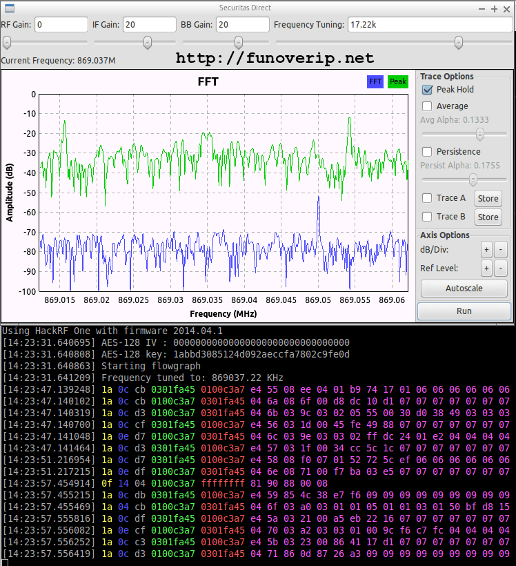
First, he took his HackRF software defined radio and monitored the 433 MHz and 868 MHz ISM bands whilst pushing keys on his alarms remote control. In the 868 MHz band he found a corresponding signal that had two spikes in the RF spectrum, indicating that it was likely a 2-FSK (frequency shift keyed) signal.
Next he created a GNU Radio program to demodulate the 2-FSK signal into a binary sequence. He then used Audacity to view and analyze the binary sequence, decoding it into 0’s and 1’s and determining the sync word (or access code). With further analysis he also determined the symbol rate and samples per symbol. With all this information gathered, he was then able to expand his GNU Radio program to automatically detect and decode packets sent by the various wireless devices connected to the alarm system.
His post goes into good detail about the steps that he took and is a great aide in understanding how to reverse engineer wireless protocols.