Category: Digital Signals

Review: Outernet LNA and Patch Antenna

Recently we posted news that Outernet had released their 1.5 GHz LNA, Patch Antenna and E4000 Elonics RTL-SDR + E4000/LNA Bundle. When used together, the products can be used to receive the Outernet L-band satellite signal, as well as other decodable L-band satellite signals like AERO and Inmarsat STD-C EGC. Outernet is a new satellite service that aims to be a free “library in the sky”. They continuously broadcast services such as news, weather, videos and other files from satellites.

EDIT: For international buyers the Outernet store has now started selling these products at http://store.outernet.is.

A few days ago we received the LNA and patch antenna for review. The patch antenna is similar to the one we received a while ago when writing our STD-C EGC tutorial, although this one is now slightly larger. It is roughly 12 x 12 cm in size, 100g heavy and comes with about 13 cm of high quality RG316 coax cable with a right angled SMA male connector on the end. The coax cable is clamped on the back for effective strain relief.

The Outernet patch antenna and LNA

The LNA is manufactured by NooElec for Outernet. It amplifies with 34 dB gain from 1525 – 1559 MHz, with its center frequency at 1542 MHz. It must be powered via a 3 – 5.5V bias tee and draws 25 mA. The package consists of a 5 x 2.5 cm PCB board with one female and one male SMA connector. The components are protected by a shielding can. Inside the shielding can we see a MAX12000 LNA chip along with a TA1405A SAW filter. The MAX12000 (datasheet here) is an LNA designed for GPS applications and has a NF of 1 dB. It has a design where there are two amplifiers embedded within the chip, and it allows you to connect a SAW filter in between them. The TA1405A SAW filter appears to be produced by Golledge (datasheet here), and it has about a 3 dB insertion loss.

The Outernet L-Band LNA
Inside the Outernet LNA

We tested the patch and LNA together with one of our V3 RTL-SDR Blog dongles, with the bias tee turned on. The LNA was connected directly to the dongle, with no coax in between. The patch antenna was angled to point towards the Inmarsat satellite. A 5 meter USB extension cord was then used to interface with a PC. The images below demonstrate the performance we were able to get.

Outernet Signal
Outernet Signal with 4x Decimation
AERO
STD-C EGC
Outernet Signal Outernet Signal with 4x Decimation AERO STD-C EGC

The Outernet team writes that a SNR level of only 2 dB is needed for decoding to work on their signal. With the patch and LNA we were able to get at least 12 dB so this is more than good enough. Other signals such as AERO and STD-C EGC also came in very strongly. Even when not angled at the satellite and placed flat on a table it was able to receive the signal with about 5 dB’s of SNR.

In conclusion the patch and LNA worked very well at receiving the Outernet signal as well as AERO and STD-C EGC. We think these products are great value for money if you are interested in these L-Band signals, and they make it very easy to receive. The only minor problem with the patch antenna is that there is no stand for it, which makes it difficult to mount in a way that faces the satellite. However this issue can easily be fixed with some sellotape and your own mount.

In the future once the Outernet Rpi3 OS and decoder image is released we hope to show a demonstration and tutorial on receiving Outernet data.

Review: Outernet LNA and Patch Antenna

Recently we posted news that Outernet had released their 1.5 GHz LNA, Patch Antenna and E4000 Elonics RTL-SDR + E4000/LNA Bundle. When used together, the products can be used to receive the Outernet L-band satellite signal, as well as other decodable L-band satellite signals like AERO and Inmarsat STD-C EGC. Outernet is a new satellite service that aims to be a free “library in the sky”. They continuously broadcast services such as news, weather, videos and other files from satellites.

EDIT: For international buyers the Outernet store has now started selling these products at http://store.outernet.is.

A few days ago we received the LNA and patch antenna for review. The patch antenna is similar to the one we received a while ago when writing our STD-C EGC tutorial, although this one is now slightly larger. It is roughly 12 x 12 cm in size, 100g heavy and comes with about 13 cm of high quality RG316 coax cable with a right angled SMA male connector on the end. The coax cable is clamped on the back for effective strain relief.

The Outernet patch antenna and LNA

The LNA is manufactured by NooElec for Outernet. It amplifies with 34 dB gain from 1525 – 1559 MHz, with its center frequency at 1542 MHz. It must be powered via a 3 – 5.5V bias tee and draws 25 mA. The package consists of a 5 x 2.5 cm PCB board with one female and one male SMA connector. The components are protected by a shielding can. Inside the shielding can we see a MAX12000 LNA chip along with a TA1405A SAW filter. The MAX12000 (datasheet here) is an LNA designed for GPS applications and has a NF of 1 dB. It has a design where there are two amplifiers embedded within the chip, and it allows you to connect a SAW filter in between them. The TA1405A SAW filter appears to be produced by Golledge (datasheet here), and it has about a 3 dB insertion loss.

The Outernet L-Band LNA
Inside the Outernet LNA

We tested the patch and LNA together with one of our V3 RTL-SDR Blog dongles, with the bias tee turned on. The LNA was connected directly to the dongle, with no coax in between. The patch antenna was angled to point towards the Inmarsat satellite. A 5 meter USB extension cord was then used to interface with a PC. The images below demonstrate the performance we were able to get.

Outernet Signal
Outernet Signal with 4x Decimation
AERO
STD-C EGC
Outernet Signal Outernet Signal with 4x Decimation AERO STD-C EGC

The Outernet team writes that a SNR level of only 2 dB is needed for decoding to work on their signal. With the patch and LNA we were able to get at least 12 dB so this is more than good enough. Other signals such as AERO and STD-C EGC also came in very strongly. Even when not angled at the satellite and placed flat on a table it was able to receive the signal with about 5 dB’s of SNR.

In conclusion the patch and LNA worked very well at receiving the Outernet signal as well as AERO and STD-C EGC. We think these products are great value for money if you are interested in these L-Band signals, and they make it very easy to receive. The only minor problem with the patch antenna is that there is no stand for it, which makes it difficult to mount in a way that faces the satellite. However this issue can easily be fixed with some sellotape and your own mount.

In the future once the Outernet Rpi3 OS and decoder image is released we hope to show a demonstration and tutorial on receiving Outernet data.

An AIS Decoder for MATLAB and the RTL-SDR

RTL-SDR.com reader Mike wrote in to us today to let us know that he has released his AIS decoder for MATLAB and the RTL-SDR. MATLAB is a technical computing language used by many scientists and engineers in the world. Mike writes the following about his work:

Automatic Identification System (AIS) is a communication standard that is used by commercial and recreational maritime vessels to report a ship’s ID, position, course and other information. This data is used for collision avoidance, search and rescue and many other applications. AIS has the following characteristics:

  • Access protocol: Self-organizing Time Division Multiple Access (SOTDMA)
  • Transmission frequencies: 161.975 MHz and 162.025 MHz
  • Transmit Power: 2 W or 12.5 W
  • Modulation: Gaussian Minimum Shift Keying (GMSK)
  • Data Rate: 9600 bits per second

An AIS decoder that uses the RTL-SDR and MATLAB to capture AIS transmissions is posted on MATLAB Central, the MathWorks file sharing exchange. The decoder has three main components

  1. Software to connect MATLAB to the RTL-SDR and bring IQ data directly into the MATLAB workspace (http://www.mathworks.com/hardware-support/rtl-sdr.html)
  2. Demodulation and decoding algorithms to convert the IQ samples into bits and decode the AIS data (http://www.mathworks.com/products/communications/)
  3. A user interface to configure the RTL-SDR, launch the capture and decoding process, and display the decoded messages (http://www.mathworks.com/matlabcentral/fileexchange/57600-ais-decoder)

The MATLAB Central post includes MATLAB source code for the AIS decoder, captured data files from Boston and San Francisco, an app for easy configuration and operation of the decoder, and instructions for installing the RTL-SDR Hardware Support Package and AIS Decoder app.

If you want to learn how AIS works, and how to write a decoder, then a MATLAB example like this is an excellent resource.

Using a Yardstick One, HackRF and Inspectrum to Decode and Duplicate an OOK Signal

Over on his YouTube channel user Gareth has uploaded a video that shows a full tutorial on quickly decoding an On Off Keyed (OOK) signal with a HackRF (or RTL-SDR) and the Inspectrum software. Once decoded he then shows how to use a Yardstick One to duplicate the signal.

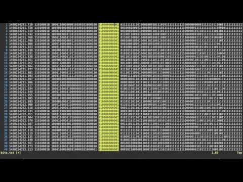
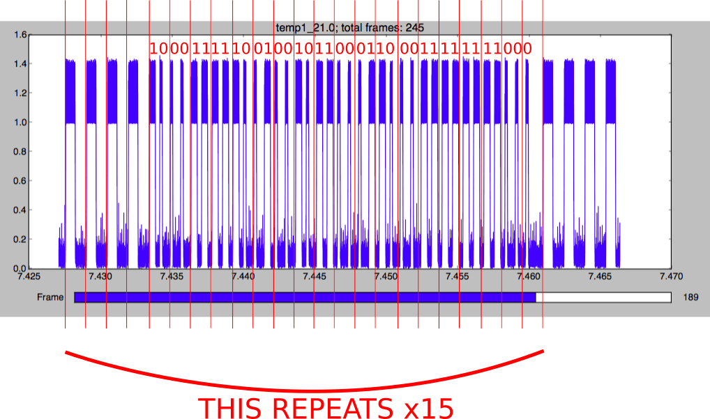
Inspectrum is a Linux based program that allows you to easily determine various parameters of a digital modulated signal by positioning an overlay over the waveform of a signal recorded with an SDR. Basically Gareth’s process is to first extract signal level values using Inspectrum, then secondly use a simple Python program to turn these values into binary bits, which gives him the data packet. He is then finally able to write another quick Python program to interface with the Yardstick One and retransmit the string.

The Yardstick One is a multipurpose radio (not a SDR) for transmitting modulated signals like OOK.

My quickest and easiest method for OOK signal decoding & replication in 2016

Receiving DAB with a Raspberry Pi 3 and RTL-SDR

Over on his blog Michael Carden has produced a tutorial showing us how to use SDR-J on the Raspberry Pi 3 for receiving Digital Audio Broadcast (DAB) radio. DAB is a type of digital broadcast radio used in several countries outside of the USA for general broadcast radio programs. It usually provides clearer digital audio compared to FM broadcast.

His post starts from scratch, showing how to create a Raspberry Pi image file and configure the Pi, then shows how to install and use SDR-J.

SDR-J is also available for Windows and is compatible with the RTL-SDR and other radios such as the Airspy and SDRplay.

SDR-J Running on Windows.

Building an S-Band Antenna for the HackRF

Mario Filippi, a regular contributor to our blog and to the SDR community recently wrote in with an article showing how he built an S-Band (2 – 4 GHz) antenna for use with the HackRF. Of course the antenna can be used with any other SDR that can receive in this range, or with an RTL-SDR and downconverter. We post his article below.

S -Band Antenna for use with the HackRF One
Author: Mario Filippi, N2HUN

Ever since purchasing a HackRF One, which receives from 1 MHz – 6.0 GHz I’ve always wanted to explore the world above 1 Gig, specifically the 2.0 – 2.7 GHz portion of the S-band. This portion of the band is populated with satellite communications, ISM, amateur radio, and wireless networks. A good, homebrew antenna for S-band was needed, so with parts mostly from the junk box, a 2250 MHz S-band right hand circularly polarized omni-directional antenna was built. Below is a step by step tutorial on building this antenna. Plans were from UHF-Satcom’s site.

The final S-band antenna

Continue reading

Decoding a Garage Door Opener with an RTL-SDR

After listening to dock workers with his RTL-SDR for a few days, RTL-SDR.com reader Eoin decided that he wanted to try a more practical experiment. He decided to see if he could reverse engineering the wireless protocol on his garage door opener. Upon opening his remote he discovered a bunch of DIP switches, which are presumably used to program the remote to a particular garage door. Eoin’s next step was to determine at what frequency the garage door opener was transmitting at. He made an assumption that it would be in the 433 MHz unlicenced ISM band as this is where many handheld remotes transmit at. He was right, and found the signal.

The garage door remote showing the DIP switches.

His next step was then to record the signal audio in Audacity. From the audio waveform he could see a square wave which looked just like binary bits. By manually eyballing the waveform and translating the high/low squarewave into bits he was able to get the binary data. He then confirmed this data with the dipswitch positions and discovered that a 010 binary code matched with the UP position on the dip switch and 011 matched with the DOWN position.

Having decoded the signal manually fairly easily, Eoin decided his next challenge would be to automate the whole decoding in GNU Radio. In the end he was successful and managed to create a program that automatically determines the position of the DIP switches from the signal. His post goes into detail about his algorithm and GNU Radio program.

Showing the decoded DIP switch positions from his GNU Radio program.

LuaRadio: New Flowgraph Based Digital Signal Processing Framework for SDR

LuaRadio is a new Digital Signal Processing (DSP) framework for software defined radios such as the RTL-SDR. It is similar to GNU Radio in that the flowgraph is composed of graphical blocks that can be visually connected to one another in an editor. However compared to GNURadio it aims to be very lightweight in terms of disk space used (1 MB footprint) and the number of dependencies required (zero dependencies required unless you need real time highly optimized libraries). It is also written purely in the Lua programming language. The authors of LuaRadio write “LuaRadio is more inclined towards scripting and prototyping than GNU Radio, and emphasizes fast block development.”

On their website there are already several example application flowgraphs uploaded, such as decoders for WBFM Mono/Stereo, NBFM, AX.25, POCSAG, RDS, AM and SSB. Looking and building such flowgraphs is extremely helpful for learning DSP, and DSP languages like this are excellent for prototyping new signal decoders. In addition, if you are new to SDR they also have a very useful page that explains basic SDR and radio concepts.

A LuaRadio based POCSAG decoder flowgraph.

Sniffing ANT-FS with an RTL-SDR and MMDS Downconverter in Pothos

ANT-FS is a wireless file transfer protocol that is designed specifically for transferring files wireless between two devices. It is designed for ultra low power devices and typically runs on devices operated by a coin sized battery. It is commonly used in applications like fitness tracker devices, which store data to later be downloaded to a PC.

Over on YouTube user sghctoma has uploaded a video showing a teaser of him receiving and decoding ANT-FS packets with blocks developed for the POTHOS graphical language. As ANT-FS is usually transmitted at 2.4 GHz, he had to use a MMDS downconverter which allowed his RTL-SDR to receive the packets. Sghctoma writes that the video is simply a teaser, and that a live demo with real deivce, and the full code + details will be released during his talk at DEFCON titled “Help, I’ve got ANTs!!!”.

ANT-FS sniffing with RTL-SDR, an MMDS downconverter and Pothosware