DragonOS is a ready to use Linux OS image that includes many SDR programs preinstalled and ready to use. The creator Aaron also runs a YouTube channel that has multiple tutorial videos demonstrating software built into DragonOS.
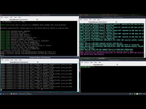
In a recent video Aaron shows how you can set up a GSM basestation within minutes by using the latest DragonOS version together with a USRP b205mini-i software defined radio. As the required software (osmo-BTS, osmo-bts, osmo-bts-trx) is all preinstalled, setting up the basestation is a simple matter of opening three terminal windows and running a few commands. We note that this latest DragonOS version is due to be released this Thursday.
In a previous video Aaron also shows a more detailed setup procedure showing how all the software was installed.
DragonOS Focal Running a GSM network in minutes (osmo-bts, osmo-bsc, osmo-bts-trx, USRP b205mini-i)
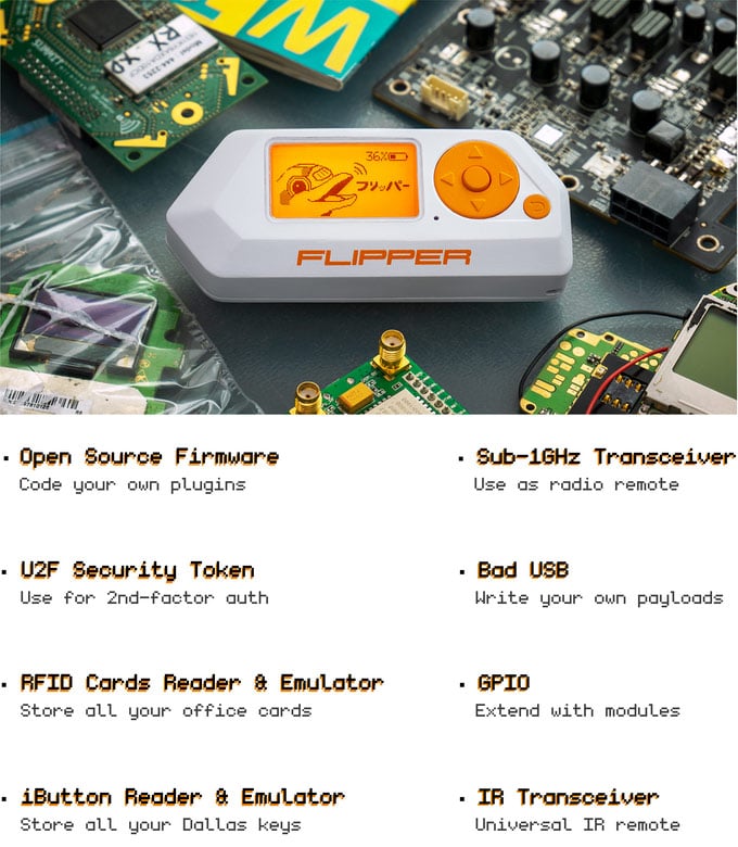
Flipper Zero isn't an SDR, but it is an interesting RF capable pentesting tool that is currently being crowdfunded, and we think it deserves a post. Based on a TI CC1101 transceiver chip, the Flipper Zero has a sub 1-GHz radio capable of doing things like emulating a garage door remote, transmitting digital signals like OOK/ASK/FSK/GFSK/MSK at 315/433/866 MHz, analyzing and decoding popular remote control algorithms like Keeloq, and reading and emulating 125 kHz RFID tags. And as the crowd funding stretch goals have already been reached, the hardware will also include a Bluetooth and NFC module.
In addition to the RF features, it has a 1-wire iButton/TouchMemory/Dallas key reader, can function as a U2F security token, has an infrared transceiver with learning feature for emulating IR remotes and has 12 5V tolerant GPIO pins available for expansion with modules such as interfaces, sensors, wireless modules and cellular modems. It can also emulate a USB slave device like a keyboard allowing you to deploy a keyboard payload.
Flipper Zero currently costs US$119 however it will soon jump to US$129 once the early bird special runs out. At the time of this post they already have 13,000 backers and have raised in excess of 2.5 million dollars. There is still 25 days left in the campaign.
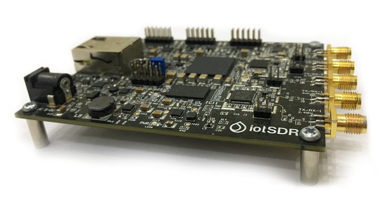
A new SDR has recently launched on the CrowdSupply crowdfunding platform. This one is called "iotSDR" and is designed to be a software defined radio to help developers and enthusiasts design custom Internet of Things (IoT) algorithms and protocols.
It has a 2-channel AT86RF215 transceiver chip which is capable of tuning to all major IoT frequencies as well as a 13-bit ADC with sample rate of up to 4 MSPS. In addition is a MAX2769B chip which is used for the GNSS reception of GPS, GLONASS, Galileo and Beidou positioning satellites. An onboard ZYNQ XC7Z010 / XC7Z020 FPGA can be used for any hardware computing required.
iotSDR currently costs US$399 for the Zync XC7Z010 FPGA version, and US$599 for the Zynq XC7Z020 FPGA version. At the time of this post there are 37 days left in the campaign.
Embedding SDR in IoT
iotSDR provides a platform that allows SDR developers and enthusiasts to design innovative algorithms and cutting-edge products. While wide-band SDRs are more versatile, narrow-band transceivers perform better for many IoT-related applications. Accordingly, iotSDR hosts two narrow-band Microchip AT86RF215 transceivers that provide their own base-band cores and have the ability to handle their own I/Q signal streaming. The result is an extremely powerful tool for anyone who is looking to simplify the task of developing, testing, and deploying high-complexity frameworks.
A Powerful FPGA and a GNSS Chip to Round It Out
iotSDR’s Microchip transceivers are backed by a Zynq SoC—which provides an FPGA and a processing system in a single package—as well as a MAX2769 GNSS chip capable of streaming live signal records. That GNSS chip can be used for custom GPS, Galileo, BieDou, and GLONASS receiver development, and is perfect for projects in the location-based services (LBS) domain such as those related to navigation and surveying.
Use Existing Software, Design a Protocol, or Build a Gateway
You can drive the hardware described above using a wide variety of popular open source software, including the Xilinx PYNQ Python framework, Jupyter Notebooks, and GNU Radio.
And if your work is further down the stack, don’t worry. iotSDR still has you covered. If you want to design and implement a physical layer IoT protocol, for example—a protocol like LoRa, SigFox, WightLess, Bluetooth, BLE, 802.15.4, ZigBee, or something of your own design—this board is for you. It’s also a great place to start if you want to build a custom IoT gateway along the lines of The Things Network, LPWAN, or Google’s Thread.
Radio has long been a pillar of modernization and technology, and this remains true in the era of software-defined radio. The Internet of Things, in particular, stands to benefit from the latest advancements in SDR technology. With iotSDR, you can be part of the community that makes that happen.
In their example Sage use a dipole antenna and analysis frequency of 30 MHz. The notebook doesn't offer much additional information, but provides Python Numpy and Scipy code which can be used to detect and plot the lightning pulses.
Back in April we posted a video from Tech Minds where he showed us how to use special software combined with an SDRplay RSPdx to detect and report VDSL interference on the HF bands. VDSL or Very High Speed Digital Subscriber Line is an internet connection technology that runs over old copper phone wires allowing for a fast broadband connection. The frequencies used by VDSL are between 25 kHz to 12 MHz, and for VDSL2 up to 30 MHz. Unfortunately the frequencies used can result in high amounts of radio interference from RFI radiating from the copper phone lines which is a major problem for HF amateurs and short wave listeners.
Recently John Rogers (M0JAV) presented a talk via the UK amateur radio organization RSGB. In the talk he explains how VDSL works, why it causes RFI and how to check for VDSL RFI using an SDR and the Lelantos software. He also shows how he drove around with a magnetic loop antenna looking for VDSL RFI sources in his neighbourhood. He then goes on to call out for more volunteers in the UK to submit RFI reports to Ofcom as they responded that they won't do anything about the interference unless there are more complaints.
The RSGB EMC Committee (EMCC) has been investigating VDSL interference since 2014. As the number of installations has risen to over 30M the interference level at amateur radio stations has also increased. The majority of radio amateurs are now impacted by this problem.
In the May 2020 RadCom we outlined how to detect and estimate the level of interference. This can be done by inspection of an SDR spectrum display or by taking a recording and then using a SW package—developed by Martin Sach of the EMCC—which identifies the VDSL signature in the recording and shows how many different VDSL lines are causing the problem and what their relative strengths are.
This talk demonstrates what to look for and how to use the tools to find out if you have a problem yourselves. We hope this will help you respond to our call for action and complain to Ofcom about the level of RFI you are subjected to.
John Rogers, M0JAV Chair EMCC
RSGB Tonight @ 8 - How to check for VDSL RFI with John Rogers, M0JAV
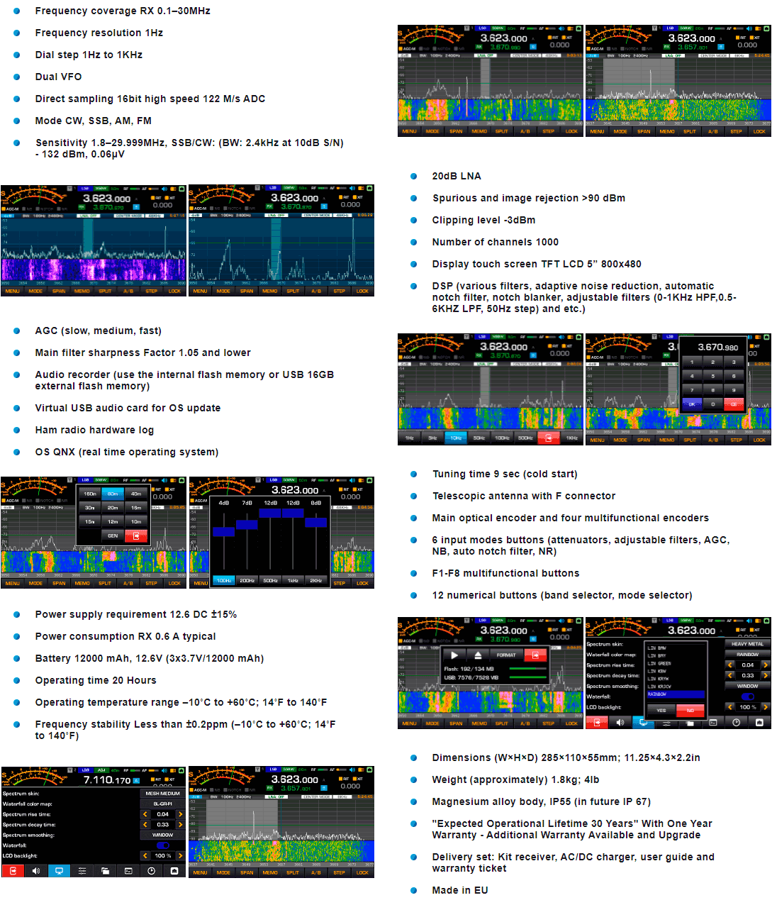
Thanks to Thomas' SWLing Blog for bringing to attention the Silphase R1 SDR receiver. This is an upcoming high performance HF SDR receiver being manufactured in the EU by a Polish company called Silphase. The R1 appears to be targeting premium SWLer customers with a price of US$1199. However, they note that by the end of 2020 they will have a 25W transceiver option, and later a 100W transceiver option. The SDR is currently available for preorder only and the sign up form can be found at the bottom of their website.
The Silphase R1 comes with a 5" touch screen that shows a spectrum display, has dual VFO's, four speakers and a metal alloy enclosure. It also comes with a built in telescopic antenna, but external antennas can be connected with the F connector. The tuning range is just the HF bands from 0.1 - 30 MHz and the ADC resolution is 16 bits.
Rendering of the upcoming Silphase R1 HF SWLing SDR
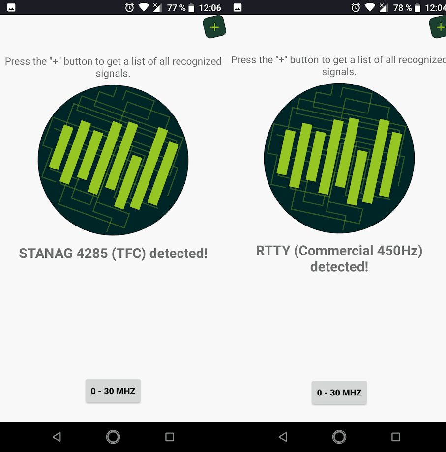
SignalID is a new Android app available on the Google Play store which offers Shazam-like radio signal identification. Just like Shazam does for music, you simply tune to an unknown signal with your SDR, play the raw audio, and let the app listen to it for five seconds. It then computes an audio fingerprint and checks to see if it knows what the signal is.
We tested the app but unfortunately we were unable to get it to detect any signals. Please write in the comments if you have success. As it uses audio fingerprinting, the app is probably highly dependant on choosing the correct demodulator (AM/FM/SSB etc), and also the tuning and signal quality. We note that most of the signal sources seem to come from our sister site the Signal ID Wiki. Searching through the wiki is a good alternative if automated solutions fail.
However the the app is new and we expect improvements and more signals to be added in the future. Currently the following signals can be recognized:
We note that this app reminds us of a Python based signal identification app for the PC called "audio_recognition_system" which we posted about earlier this year.
SignalID: Shazam-like audio based signal identification for Android.
In this episode of Frugal Radio's series of SDR beginners guide videos he discusses some antenna basics. He shows the most common types of antennas, provides several tips to help improve reception, and shows how to properly tune antennas using online calculators.
Near the end of the video he shows our multipurpose dipole antenna kit and shows how to adjust the telescopic elements for best reception. He demonstrates that simply extending the elements to the maximum length does not result in the best tuning, rather you need to tune the element length for the frequency being received to get the best results.
2020 SDR Guide Ep 4 : Antenna Basics for SDR Beginners inc RTL-SDR / Nooelec NESDR SMArt bundle