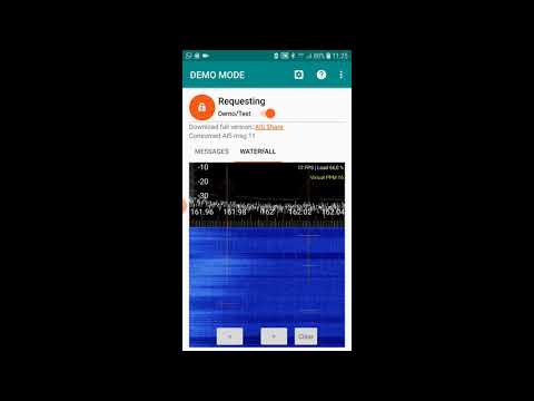
Thank you to Christian, author of the RTL-SDR AIS Android App for letting us know that he's updated his app and it now includes a waterfall display for tuning the AIS frequency. Tuning the AIS frequency is not required on higher end RTL-SDR dongles that come with a TCXO (Temperature Compensated Oscillator), but cheaper RTL-SDRs will have significant frequency offsets that will require the offset to be determined after a few minutes of warm up time. The easiest way to do this is with a waterfall display as that allows you to tune the frequency manually.
AIS stands for Automatic Identification System and is used by ships to broadcast their GPS locations in order to help avoid collisions and aide with rescues. An RTL-SDR with the right software can be used to receive and decode these signals, and plot ship positions on a map.
SDRplay have recently released an update on how the Coronavirus is impacting their supply lines. In short, they note that their fulfillment is currently normal, but there may be delays in the logistics distribution network. In terms of stock levels, they have enough to cover a few more weeks of normal buying, but beyond that the supply chain is not certain and there may be restocking delays.
Dear customer,
We have been fortunate that our suppliers have been able to source the components needed to fulfil our current backlog commitments. In particular the demand for the new RSPdx exceeded our expectations, and that has caused shortages up until now.
However we now have enough product available to continue supply of all three SDRplay production RSPs for a few more weeks at traditional buying levels. Beyond that, we will be dependent on our subcontract manufacturing partners’ ability to source components. As the coronavirus situation unfolds it is likely that restocking will take significantly longer than usual and we are working with both suppliers and our distributors to do our best to plan for the uncertain future.
Meanwhile, regarding orders placed in the next week or so, SDRplay and its fulfilment centres are currently working as normal, BUT please be aware that logistical delays in the distribution network are likely – so please be patient if your shipment takes longer than expected.
We’d also like to take the opportunity to send our best wishes to all our customers and their friends and families as this emergency situation develops.
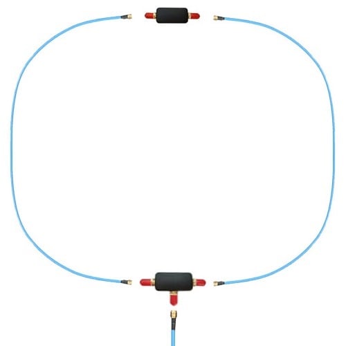
We have recently been able to obtain a small number of YouLoop HF/VHF portable receive only passive antennas that were produced by the owner of Airspy. The YouLoop is available in our store priced at US$34.95 including free worldwide shipping. It comes with the balun "tee" connector, coax inverter, 2x 1m semi-rigid coax cables for a ~60cm loop, and 1x 2m semi-rigid coax for the feedline. Note that US customers may wish to purchase from airspy.us as they have local US stock. We are focusing on non-US orders for this product and we only have very limited stock at the moment - UPDATE: Now out of stock. We have reordered more and should be back in stock by end of March.
YouLoop Portable Passive Magnetic Loop Antenna for HF and VHF
If you don't know what a "YouLoop" is, it is a simple passive magnetic loop antenna design which consists of a ring of coax cable and a low loss 1:1 or 4:1 balun. The design was recently popularized by Youssef (prog) the owner of Airspy, and he has put up a page explaining how the design works here. Many users on Twitter have been reporting good results with HF reception with the design. It appears to be especially useful in urban environments where there is lots of local noise.
Left Discovery with YouLoop Antenna, Rigth Discovery with HF Hoxin Vertical Antenna.
Same configuration in sdr#, both in roof with 25m RG213 cable.
A lot of noise in the vertical antenna, Barcelona noisy city. pic.twitter.com/NNYdpsmNTo
Being passive, it has no amplification and so it works best with a low noise SDR like an Airspy HF+. However we have also found decent results with SDRplay SDRs, and a standard RTL-SDR Blog V3 running in direct sampling mode, although RTL AGC mode needs to be turned on for an extra boost. Improved results can be obtained by using a low cost HF amplifier on the front end, and even our wideband LNA which is advertised as working down to 50 MHz still does actually give a decent boost from 5 MHz and up.
Also the design has some advantages in that it has very low electrical interference pickup, and has no electronics that can overload from signals that are too strong. Overloading from strong signals is something that can easily affect cheap magnetic loop antennas like the MLA-30, and even higher end loop antennas too. Being a magnetic loop, it also naturally filters out electric field interference which is extremely common in urban environments, and is the reason why e-field antennas like miniwhips often perform poorly.
The antenna is designed to be extremely portable, being lightweight and easy to assemble/disassemble. As such it is not designed to be weatherproof, so if you do decide to mount it permanently please make use of weatherproofing tape.
Unlike fixed magnetic loops, the YouLoop design is also easy to experiment with. By using longer coax cables you can easily create a larger loop which can result in stronger signals. We found that replacing the 1m loop cables with 2m lengths gave quite nice results for us. If you have the space you could try even larger loops too.
The design also doubles as a great VHF antenna with reception up to 300 MHz possible when used in a folded dipole configuration. To do that, simply flatten the loop into a dipole shape.
Finally, if you prefer the YouLoop can also be constructed by yourself. The Twitter post below shows the basic design. Search Twitter for "YouLoop antenna" for more discussion on the design too.
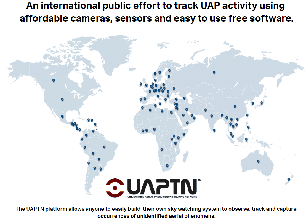
The Unidentified Aerial Phenomenon Tracking Network (UAPTN) is an effort to set up crowd sourced Raspberry Pi powered cameras all over the world in order to record videos of "unidentified aerial phenomena" AKA UFOs. In order to rule out false positives from known aircraft, they are recommending that contributors install a FlightAware RTL-SDR in their system for aircraft tracking.
For this purpose doing your own ADS-B flight tracking would be required as most commercial flight tracking sites censor military and private jets. The only site that does not censor data is ADS-B Exchange. However, of course military aircraft conducting operations are always able to turn ADS-B off if required for the mission which is what the UAP network will probably detect the most.
If UFO tracking does not interest you, then you might instead be interested in creating a RTL-SDR based GhostBox to talk to spirits!
A few days ago we posted about the release of the new NooElec Ham-It-Up Nano upconverter which sells for US$49.95 on their store and Amazon. Upconverters enable SDRs that cannot tune in the HF bands to receive HF by shifting the low HF frequencies "up" into a range receivable by most VHF/UHF capable SDRs.
In his latest video Techminds reviews the Nano together with an E4000 tuner based RTL-SDR with built in bias tee. In the video he demonstrates it working with the SDR# software, and shows how to set the Shift parameter to ensure that the correct frequency offset it set. He goes on to demonstrate reception through the various HF bands confirming that the unit works as expected.
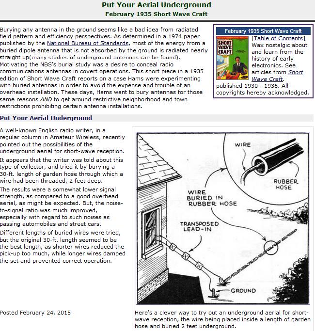
Thank you to Jean-Marie Polard (F5VLB) for letting us know about his work in creating underground "earth probe" antennas that work for both RX and TX between 0 - 14 MHz, and are especially good at VLF and below. He writes:
Can't install an antenna at home? Madame refuses the masts, taut son? One solution, The Earth probes antenna.
Our group (https://www.facebook.com/groups/earthprobes/) started in January 2019. At first everyone made fun of me, the professionals called me crazy and today with more than seven hundred members, we installed underground antenna systems and the results are there.
Between 0 and 14MHz, in transmission and reception, it works!
This system dates from 1914/1918 but has been brought up to date.
It doesn't take much to get started, just the urge to try.
To access the Earth Probes and VLF.ULF.ELF groups you'll need a Facebook account. The groups contain a number of research papers documenting the concept, and the photos section. From the photos, an earth probe antenna appears to consist of two long grounding rods spread over a distance, or a grounding rod and long buried wire, combined with a balun.
An example of an underground antenna setup from a 1935 shortwave magazine.
CENOS are a company specializing in 3D modelling and simulation software for induction heating applications. However, they are now branching out and are creating software for antenna design and simulation. Final pricing of the software is not yet advertised, but they write that it has been made affordable thanks to "open source algorithms". Hopefully it will be affordable to hobbyists, but judging by the heat simulation software pricing it may not be (although they offer to software free to students, researchers and teachers).
However, it appears that they will soon be running a beta testing program that should hopefully be free to use during the testing phase. You can sign up to their email list and wait for their announcement on their website.
Hamvention, the largest yearly amateur radio event has been cancelled this year due to concerns over the spread of the Coronavirus (COVID-19). It was due to be held during May 15 - May 18, 2020. Chairman Jack Gerbs writes:
The Hamvention Executive Committee has been monitoring the COVID19 pandemic. We have worked very closely with our local and state health Departments.
It is with a very heavy heart the Hamvention Executive Committee has decided to cancel Hamvention for this year. This decision is extremely difficult for us but with around two months until the Great Gathering we felt this action necessary. More specific details regarding the closure will soon be posted here.
Thank you for your understanding in this time of International Crisis.
According to the ARRL cancelled events tracker, a number of other amateur radio events across the USA have also been cancelled, and we're seeing similar reports for most other countries too. At this stage we expect that most events will be cancelled over the next few months.
RTL-SDR Blog V3 Stock & Shipments
Due to manufacturing delays and slowdowns related to the Coronavirus our multipurpose dipole antenna set, and set including antenna and dongle is currently out of stock on our international webstore. We expect to be able to restock by the end of the month. There remains sufficient stock of the dongle itself. Our wideband LNA will also be back in stock next month.
Amazon USA is still stocked with all products, however there may be a short out of stock period within 1-2 weeks as we await for the arrival of replenishing stock in the USA.
In regards to international shipments please expect that there could be delays. At the moment we are seeing most mail still getting through in a timely manner, however this could change over the coming weeks as more travel restrictions come into play.
It is expected that other radio related products could also soon be out of stock, or delayed due to the situation.
Other Coronavirus Posts
N0SSC has provided a good post outlining the risks to the amateur radio population and why amateur radio event cancellations are a good idea.
We thought it would be nice to put out a special edition of the podcast to help listeners keep up their morale during this difficult time. So we’ll do our regular kind of show, but we’ll try to emphasize things you can do to stay busy and keep up morale while stuck at home.
Over on The SWLing Blog Thomas has put out a post about social distancing and how to keep occupied without leaving the house, and another post about how shortwave broadcasters are now adding regular Coronavirus information and news to their broadcasts.