On The Thought Emporium YouTube channel a new video has been uploaded showing the full disk images of the earth that they've been able to receive from GOES geosynchronous weather satellites. Over the past couple of years GOES satellite reception has become much easier for hobbyists to achieve with the release of the NooElec SAWbird LNA+Filter, information on how to use a cheap 2.4 GHz WiFi grid antenna for reception and the release of free open source decoder software. It was also shown that an RTL-SDR dongle is sufficient for receiving these images as well. With all these new developments it is now possible to build a GOES receiving station for under $100.
The Thought Emporium video blurb reads:
In the fall of 2016 I saw my first rocket launch and little did I know that the satellite on that rocket would come to shape and fill my thoughts for many years. We're no strangers to getting data out of space on this channel, but GOES-16 is special, and not just because I was there when it left earth. Unlike the satellites we looked at in the past, GOES is in geostationary orbit and has an amazing suite of cameras and sensors on board. While it's a bit harder to receive data from GOES the extra effort is absolutely worth it, especially because it can see then entire globe all at once and send out those images in stunning high resolution. And it even comes with the added bonus of rebroadcast data from other satellites giving us a view of the opposite side of the planet as well.
In this video we go through the hardware and software needed to receive these gorgeous images and what is contained in the signals we receive.
Pulling Clear Images Directly Off Satellites | GOES-15,16,17 and Himawari 8 HRIT
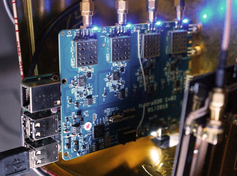
KerberosSDR is our upcoming low cost 4-tuner coherent RTL-SDR. With four antenna inputs it can be used as a standard array of four individual RTL-SDRs, or in coherent applications such as direction finding, passive radar and beam forming. More information can be found on the KerberosSDR main post. Please remember to sign up to our KerberosSDR mailing list on the main post or at the end of this post, as subscribers will receive a discount coupon valid for the first 100 pre-order sales. The list also helps us determine interest levels and how many units to produce.
In this post we'll show an experiment that we performed which was to pinpoint the location of a transmitter using KerberosSDR's coherent direction finding capabilities. RF direction finding is the art of using equipment to determine the location of a transmitting signal. The simplest way is by using a directional antenna like a Yagi to try and determine the bearing based on signal strength. Another method is using a pseudo-doppler or coherent array of antennas to determine a bearing based on phase information.
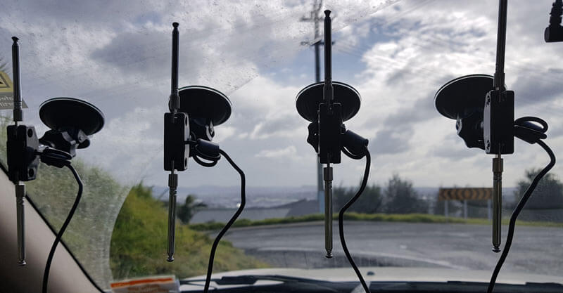
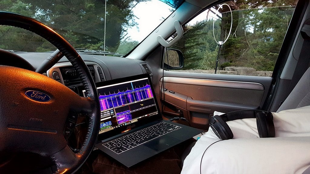
For the test we tuned the KerberosSDR RTL-SDRs to listen to a signal at 858 MHz and then drove to multiple locations to take direction readings. The antennas were set up as a linear array of four dipole antennas mounted on the windshield of a car. To save space, the dipoles were spaced at approximately a 1/3 the frequency wavelength, but we note that optimal spacing is at half a wavelength. The four dipole antennas were connected to KerberosSDR, with a laptop running the direction finding demo software.
Low cost direction finding array mounted to vehicle windshield.
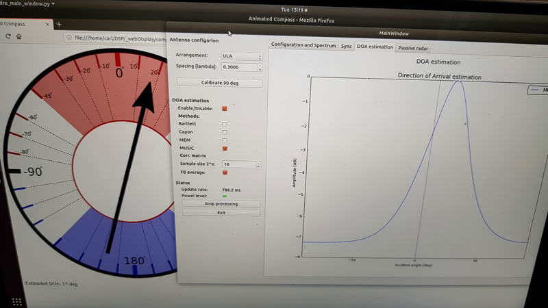
Our open source demo software (to be released later when KerberosSDR ships) developed by Tamás Peto gives us a graph and compass display that shows the measured bearing towards the transmitter location. The measured bearing is relative to the antenna array, so we simply convert it by taking the difference between the car's bearing (determined approximately via road direction and landmarks in Google Earth) and the measured bearing. This hopefully results in a line crossing near to the transmitter. Multiple readings taken at different locations will end up intersecting, and where the intersection occurs is near to where the transmitter should be.
KerberoSDR SDR Directing Finding DOA Reading
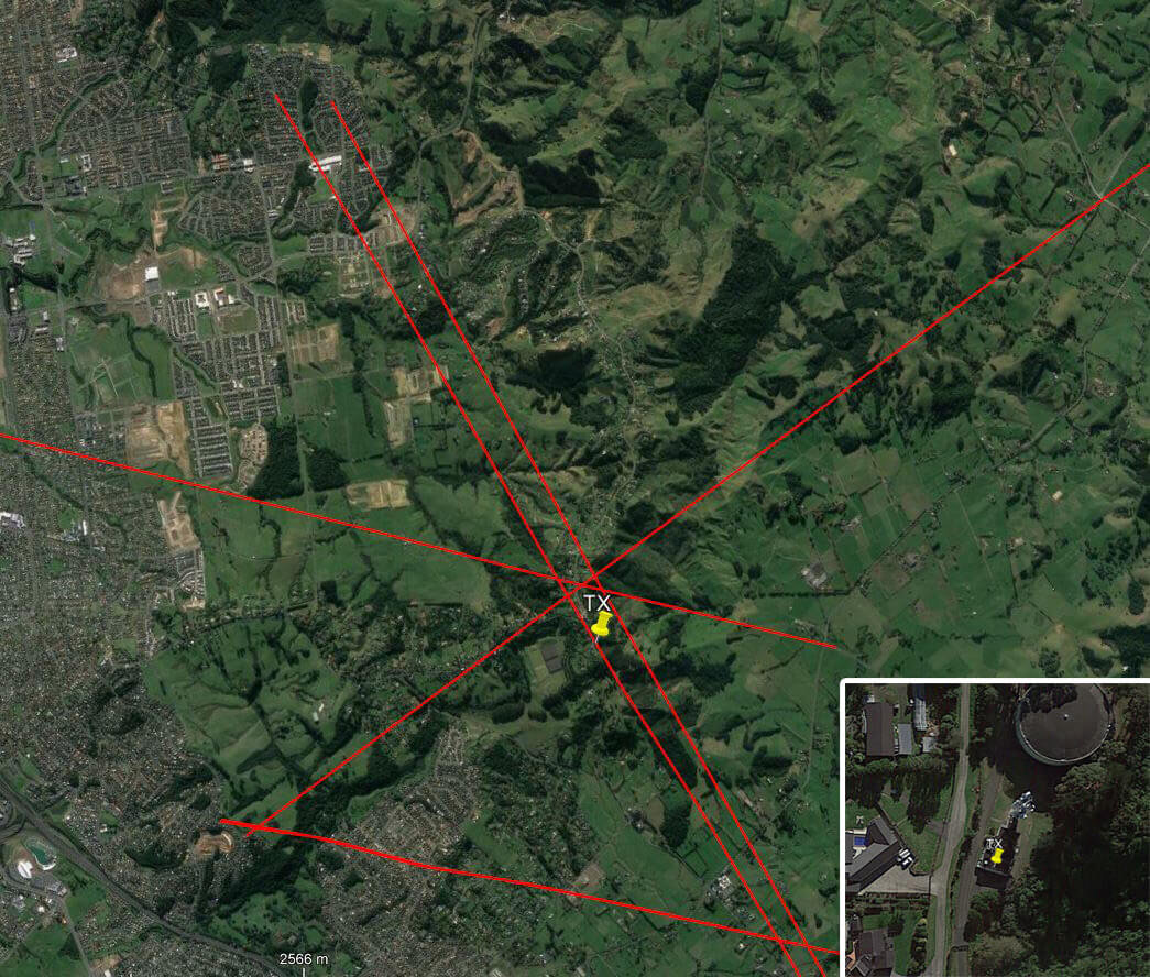
In the image below you can see the five bearing measurements that we made with KerberosSDR. Four lines converge to the vicinity of the transmitter, and one diverges. The divergent reading can be explained by multipath. In that location the direct path to the transmitter was blocked by a large house and trees, so it probably detected the signal as coming in from the direction of a reflection. But regardless with four good readings it was possible to pinpoint the transmitting tower to within 400 meters.
In the future we hope to be able to automate this process by using GPS and/or e-compass data to automatically draw bearings on a map as the car moves around. The readings could also be combined with signal strength heatmap data for improved accuracy.
This sort of capability could be useful for finding the transmit location of a mystery signal, locating a lost beacon, locating pirate or interfering transmitters, determining a source of noise, for use during fox hunts and more.
KerberosSDR pinpointing a transmitters locationKerberosSDR Prototype
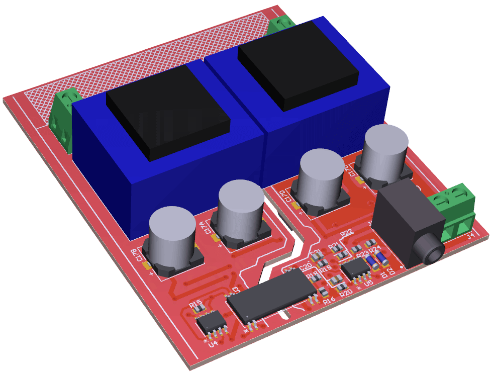
Over on Hackaday and Hackaday.io we've seen an interesting project by David Scholten called "Grid-2-Audio". The project's goal is to build a safe device for monitoring the mains electrical grid waveform via a power jack and PC soundcard. This is essentially an SDR, with the soundcard acting as the ADC for the 50Hz grid signal, and Grid-2-Audio acting as a safety isolator and signal preconditioner. About why you might want to monitor the mains power signal, David writes:
There is a lot to be observed from the waveform of the electrical mains. Harmonics, transient changes, periodic fluctuations, frequency shifts, impedance, power line communications - These all give clues as to the state of the country's electrical transmission system (or what loads your neighbour has connected). Platforms like MATLAB allow for the easy analysis of waveforms through powerful software tools, but only once the signal has been acquired.
The final product will be a black box with mains plug and a 3.5mm audio jack ready to plug into your soundcard. In order to make the device safe, mains isolation transformers are used as well as good PCB design practices that isolate live and safe areas on the PCB. In the design care is also taken to maintain signal integrity and to not introduce noise by ensuring that the power supply draws minimal sinusoidal current, and is in phase with the voltage.
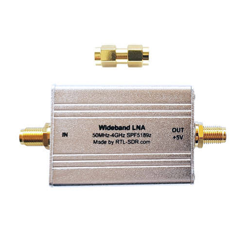
We've just released two new products in our store. The first is a low cost general purpose wideband LNA and the second is some spare RTL-SDR V3 aluminum enclosures. The wideband LNA is currently available for shipping from our Chinese warehouse and will be available on Amazon in a few days time. It costs US$17.95 including worldwide free shipping. The spare aluminum enclosure is only available from our Chinese warehouse and costs US$5.95.
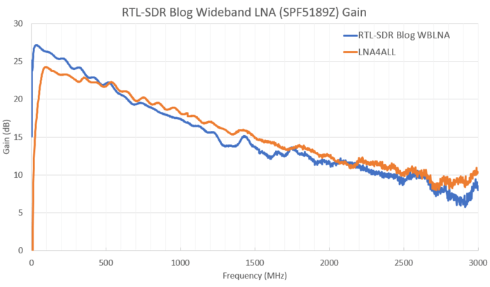
The Wideband LNA is based on the Qorvo SPF5189Z LNA chip (datasheet pdf) which has the following declared specs:
Frequency range of 50 MHz to 4000 MHz
Noise figure = 0.6dB @ 900 MHz
OIP3 = 39.5 dBm @ 900 MHz
P1 Saturation = 22.7 dBm @ 1960 MHz
Gain = 18.7 dB @ 900 MHz
Compared to most of the other SPF5189Z LNAs found on eBay, our wideband LNA comes standard with a full conductive metal case, includes ESD protection on the antenna input, and is by default powered via 3 - 5V bias tee power. Our RTL-SDR Blog V3 dongles have a 4.5V bias tee built in, so they can be used to power this LNA. Direct power can be enabled simply by changing a jumper position, and removing the metal case.
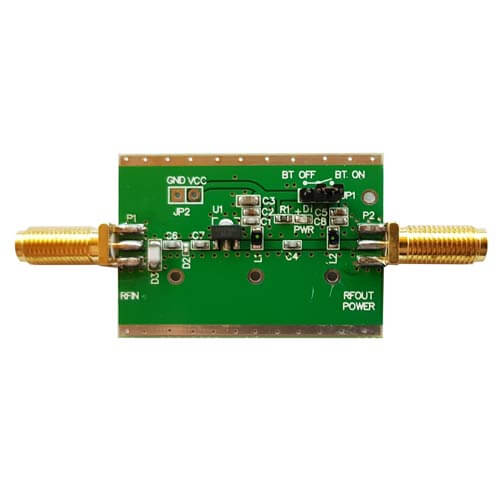
This is a general purpose wideband LNA. It is useful for reducing the noise figure and thus increasing SNR, and for overcoming coax loss on all supported frequencies between 50 - 4000 MHz. However, because it is wideband you may need additional filtering if you have strong overloading signals in your area. If you're mostly interested in improving ADS-B reception, then we instead recommend our Triple Filtered ADS-B LNA which is also available at our store. The specs of the SPF5189Z are similar to that of PGA-103+ or PSA4-5043+ based LNAs. In the image slider below we compare the gain with the LNA4ALL which is a PSA4-5043+ based LNA.
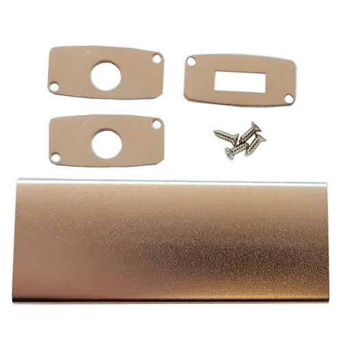
Spare Aluminum Enclosure
The second product is some spare RTL-SDR Blog V3 aluminum enclosure. A few readers of this blog contacted us as they found RTL-SDR V3 enclosures to be a good fit (after being cut down to size) for home made filters, other LNAs and for FlightAware dongles. Our spare enclosures come with two SMA side panels, and one USB side panel. There is only limited stock of this product at the moment. Note that we're not including a thermal pad, since FlightAware dongles do not require additional cooling since they operate at 1.09 GHz. Additional cooling via thermal pad is only needed for stable operation when using RTL-SDRs above ~1.5 GHz.
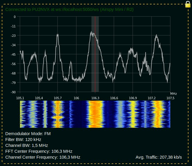
Over the last few months Lucas Teske (author of the Open Satellite Project) has been working on a piece of software called "SegDSP". The idea appears to create a web GUI based SDR receiver for SpyServer streams which can be used to create a cloud of channel demodulators, essentially segmenting the DSP computation burden over multiple computers.
SpyServer is a SDR server application that is compatible with Airspy products and RTL-SDRs. It allows you to connect to these SDRs remotely over a network or internet connection. The SDR server computer sends the radio IQ data over the network allowing you to perform processing remotely. A major advantage of SpyServer compared to other SDR server applications is that it only sends the raw IQ data for the portion of the spectrum that you're interested in which can save a lot of bandwidth.
One key application that Lucas envisions for SegDSP is using it with cloud clusters of single board computers (SBC) like the Raspberry Pi 3. The philosophy is that there will be specific roles for each SBC machine. For example you might have some SDR machines running SpyServers, some processing machines for demodulating and decoding multiple channels, and a storage machine for recording data. Then you can dynamically spawn / despawn workers when needed (for example only spawning a machine when a LEO satellite with data to decode passes over).
SegDSP development is still in the early stages, and appears to only have the web GUI set up at the moment with a few demodulators. But keep an eye on his Twitter @lucasteske for updates too. Lucas also did a talk at the last CyberSpectrum meetup. His talk can be found at 1:30:00 in the recording.
The idea behind the article is to introduce people to SDR from a shortwave listening point of view, so high performance HF SDRs like the Airspy HF+, Elad FDM-S2 and WinRadio Excalibur are discussed. Thomas notes that these SDRs can perform as well as traditional DX-grade receivers that can cost two to three times more. He also explains what advantages SDR's bring to the shortwave radio listening hobby. This may be a good article to show those still using older hardware radios that haven't yet converted to the SDR world.
The article is currently part one of a three part series, with parts two and three to be released in October and November.
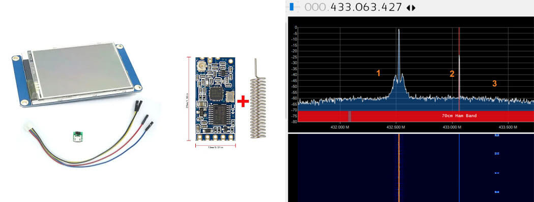
Thanks to Steve K2GOG of The Hudson Valley Digital Network (HVDN) for submitting his post on how to create a wireless display for Pi-Star. Pi-Star is a pre-built Raspberry Pi image for amateur radio users experimenting with digital voice communications like D-STAR and DMR. They write that it can be used for applications such as a "single mode hotspot running simplex providing you with access to the increasing number of Digital Voice networks, [or a] public duplex multimode repeater".
Pi-Star is compatible with serial based LED displays with built in GUIs like the Nextion. The displays are usually connected directly to the Raspberry Pi, but Steve wanted to use the display remotely. To do this he used a simple and inexpensive 70cm band HC-12 wireless serial port adapter. With the wireless adapters connected to the Pi he was able to see the pulses in SDR# via his RTL-SDR to confirm that the wireless serial signal was being sent. He then connected the second wireless adapter to the Nextion display via a few diodes to drop the voltage, and was able to get the display updating as if it was connected directly.
In the post Steve mentions that HVDN are also giving away an HC-12 and RTL-SDR to the first person to submit some progress with this idea.
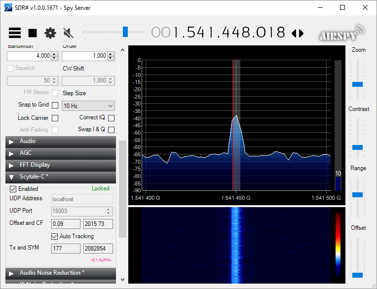
Microp11, the programmer of Scytale-C a standalone Inmarsat decoder has just released a new Inmarsat decoder SDR# plugin. The plugin is currently in the "pre-alpha" stages, so is still missing some functionality and may be buggy. However, it does appear to be functional at this point in time. It can be used with RTL-SDRs, and any other SDR# compatible SDR including units running on remote SpyServers. Microp11 writes:
I ran it with SDR# version v1.0.0.1761.
If it crashes you SDR# I apologize in advance.
The auto-tracking (default on) will alter your SDR# frequency and follow the signal’s CF. When the SNR is very low, please disable it and manually tune the SDR# to try to get the CF as close to 2000 as possible.The demodulator still has plenty ideas of its own.
Use USB mode with 4000 Hz bandwidth.
For now the interface is missing the usual scatter plots.
UDP Address and UDP Port are for sending the decoded frames to the Scytale-C UI.
Offset and CF are the difference from zero error and the CF frequency of the demodulated BPSK signal.
Tx and SYM are the transmitted over UDP frames and SYM is showing the number of demodulated symbols.
A bunch of libraries are attached as extra files. Please be gentle and accept the package as it. Will clean-up in the future.
Use in conjunction with the Scytale-C UI from the archive: “x64-UI1.6-Decoder1.4.zip” (link below)
The magic line is included in the archive: “SDRSharp.ScytaleC-1.0-alpha.zip”