Thanks to RTL-SDR.com reader 'flatflyfish' for submitting information on how to get Martin Marinov's TempestSDR up and running on a Windows system. If you didn't already know by definition "TEMPEST" refers to techniques used by some spy agencies to eavesdrop on electronic equipment via their unintentional radio emissions (as well as via sounds and vibrations). All electronics emit some sort of unintentional RF signals, and by capturing and processing those signals some data can be recovered. For example the unintentional signals from a computer screen could be captured, and converted back into a live image of what the screen is displaying.
TempestSDR is an open source tool that allows you to use any SDR that has a supporting ExtIO (such as RTL-SDR, Airspy, SDRplay, HackRF) to receive the unintentional signal radiation from a screen, and turn that signal back into a live image. This can let you view what is on a screen without any physical connections. If a high gain directional antenna is used then it may be possible to receive images from several meters away as well.
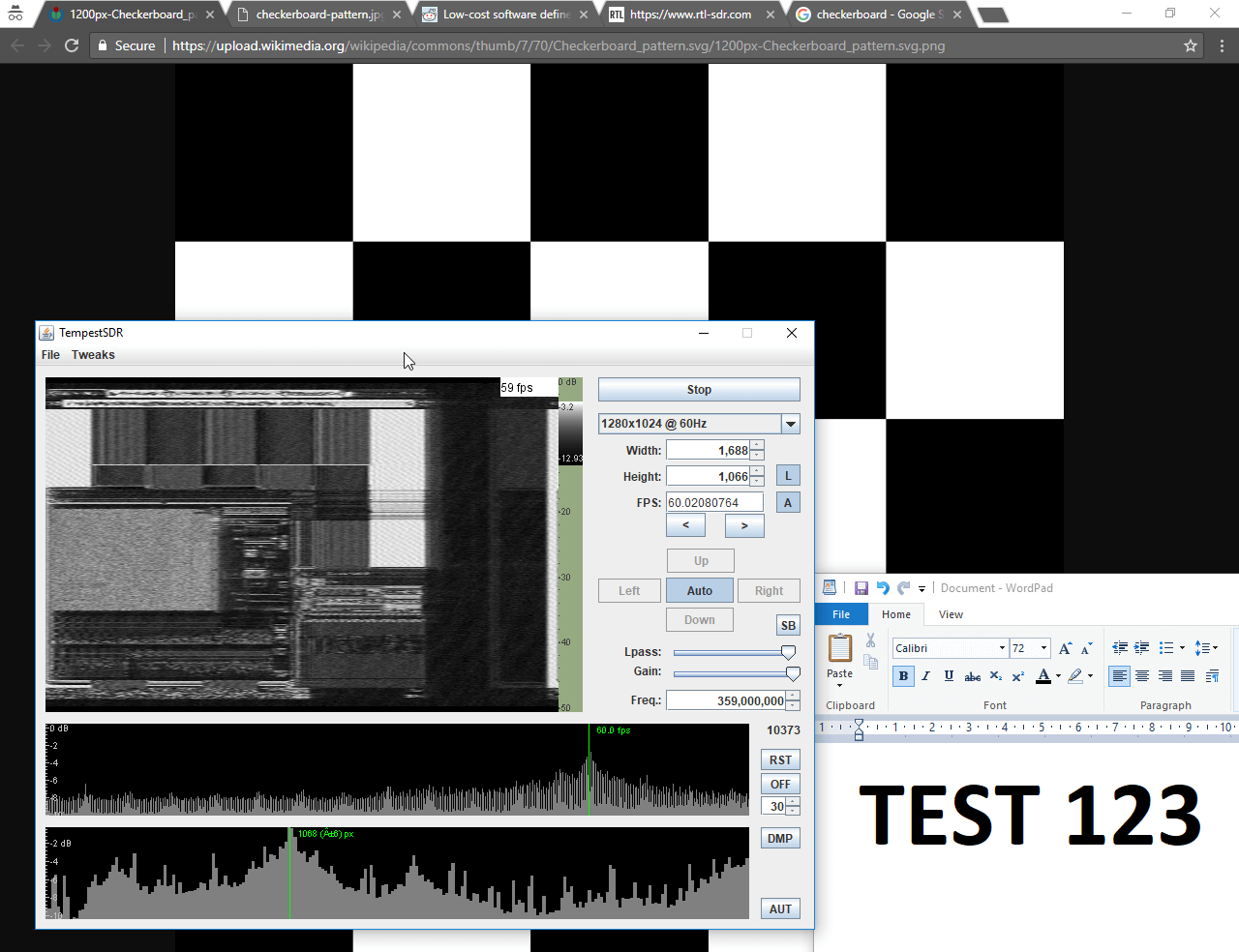
TempestSDR showing what's on the screen via unintentional RF radiation from the monitor.
Although TempestSDR has been released now for a number of years it hasn't worked properly in Windows with ExtIO interfaces. In his email flatflyfish showed us how to compile a new version that does work.
1. You need to install a 32-bit version of the Java runtime. The 64-bit version won't work with extio's possibly because they are all 32-bit. Also install the JDK.
2. You need to install MingW32 and MSYS and put their bin folders in your Windows PATH.
3. Then when compiling I was seeing a lot of CC command unknown errors. To fix that I just added CC=gcc to the top of all makefiles. I also removed the Mirics compilation line from the JavaGUI makefile to make things easier as we're not using that sdr.
4. Originally my JDK folder was in Program Files. The makefile didn't like the spaces in the folder, so I moved it to a folder without spaces and it fixed the errors.
5. Lastly to compile it you need to specify the ARCHNAME as x86 eg "make all JAVA_HOME=F:/Java/jdk1.7.0_45 ARCHNAME=X86"
After doing all that it compiled and I had a working JAR file. The extio's that are used normally with HDSDR work fine now and I get some images from my test monitor with an rtlsdr.
We tested compilation ourselves and were successful at getting a working program. To help others we've just uploaded a fork of the code with the makefile changes done, as well as a precompiled release ZIP available on the releases page so no compilation should be required to just use it. Note that to use the precompiled JAR you still need to install MingW32, and also don't forget to install the MingW /bin and msys /1.0/bin folders into the Windows PATH. You also do need to have the 32-bit Java runtime installed as the 64-bit version doesn't seem to work. On at least one Win 10 machine we also had to manually add a 'Prefs' folder to the Java path in the registry.
We've tested the software with the ExtIO for RTL-SDRs (available on the HDSDR downloads page) and confirmed that it works. Images from one of our older DELL monitors using DVI are received nicely, although they are a bit blurry. We also tried using an Airspy or SDRplay unit and this significantly improved the quality of the images a lot due to the larger bandwidth. The quality was good enough to make out large text on the screens. ExtIO's for the Airspy are available on this page, and for the SDRplay on the official SDRplay website. Note that for the SDRplay we were unable to go above 6 MHz, and on the RTL-SDR 2.8 MHz was the limit - anything higher on these SDRs did not produce an image possibly due to dropped samples.
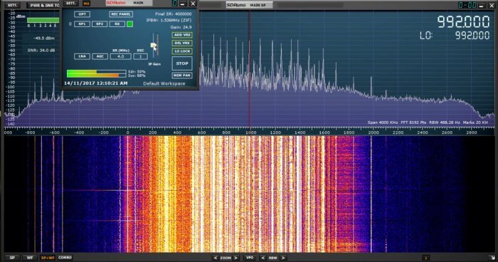
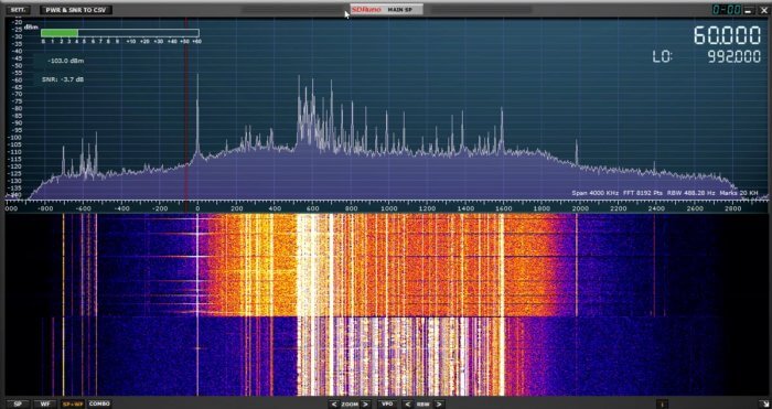
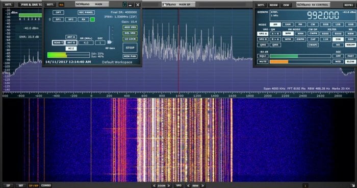
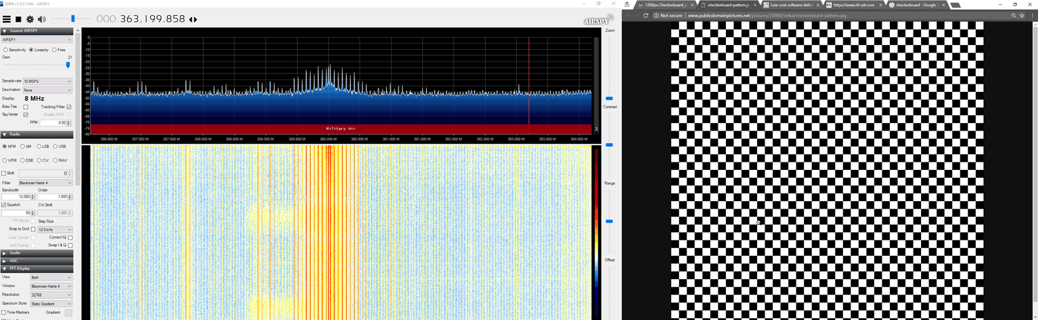
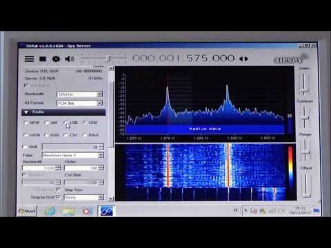
To use the software you should ideally know the resolution and refresh rate of your target monitor. But if you don't there are auto-correlation graphs which actually help to predict the detected resolution and frame rate. Just click on the peaks. Also, you will need to know the frequency that your monitor unintentionally emits at. If you don't know you can browse around in SDR# looking for interference peaks that change depending on what the image of the screen is showing. For example in the image below we show what the interference might look like. A tip to improving images is to increase the "Lpass" option and to watch that the auto FPS search doesn't deviate too far from your expected frame rate. If it goes too far, reset it by re-selecting your screen resolution.
Unintentionally radiated RF signal from computer screen shown in SDR#
The best results were had with the Airspy listening to an older 19" DELL monitor connected via DVI. A newer Phillips 1080p monitor connected via HDMI had much weaker unintentional signals but images were still able to be recovered. A third AOC 1080p monitor produced no emissions that we could find.
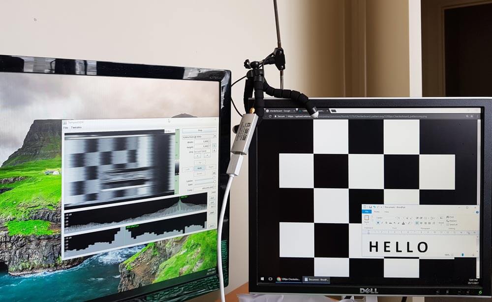
Clear images were obtained with an antenna used in the same room as the monitor. In a neighboring room the images on the DELL monitor could still be received, but they were too blurry to make anything out. Possibly a higher gain directional antenna could improve that.
An example set up with RTL-SDR antenna and monitors
Below we've uploaded a video to YouTube showing our results with TempestSDR.
TempestSDR - Remotely Eavesdropping on Monitors via Unintentionally Radiated RF
Airspy have just tweeted a Black Friday deal for their products sold on iTead Studio. Simply use the coupon "AIRSPYBLACK" when checking out. It looks like the coupon is giving 15% off the Airspy Mini and Airspy R2. No discounts yet for the Airspy HF+ or SpyVerters.
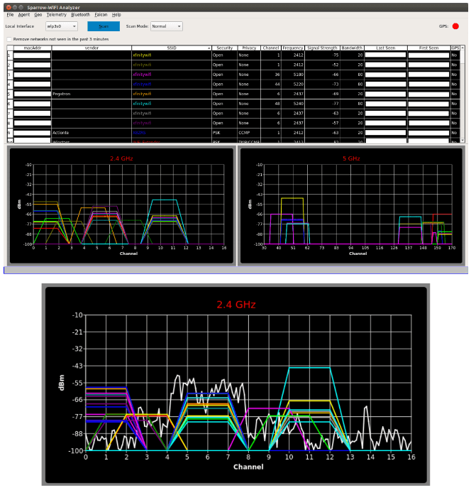
Thanks to Mike (ghostop14) for submitting another interesting article this time about his work with spectral fusion on the WiFi and Bluetooth bands. In the article Mike describes his new Sparrow-WiFi tool, which is a tool that allows you to visualize the WiFi and Bluetooth signal spaces all in one spectral display. The hardware consists of a WiFi and Bluetooth dongle as well as optionally an SDR like the HackRF. The software displays all data simultaneously on the same display, so you can easily tell if there is some channel clashes occurring, or if there is some other source of interference. In Addition Sparrow-WiFi also works remotely and even with a Raspberry Pi mounted on a drone.
From the article he writes:
Thinking about the 2.4 and 5 GHz bands, my biggest issues with traditional wifi tools were always that apps such as inSSIDer which are great on the Windows side didn’t have a nice polished Linux GUI equivalent so I’d have to run a Windows system or virtual machine to visualize the signal space. On the flip side, some of the great Linux-only capabilities didn’t have a nice polished integrated UI and I’d have a lot of textual data, some of which the Windows tools didn’t provide, but it was harder to visualize. Then there’s the fact that wifi tools can’t “see” Bluetooth (and vice versa), and SDR historically didn’t have enough instantaneous bandwidth to show the whole 2.4 GHz or 5 GHz spectrum at one time. And, did I mention the tools don’t integrate or talk to each other so I can’t get a “single pane of glass” perspective of all the different ways to look at the same RF space simultaneously? It would be great if I could get one single view of the most common protocols and see the actual spectrum all in one place at the same time.
Now enter the era of the Internet-of-Things, new SDR receivers, and even drones and my old wifi tools seem to have been left a bit behind. Why do I say that? I can’t “see” all of the chatter from wireless networks, Bluetooth, ZigBee, NEST devices, remotes, etc. scattered all over my wireless bands in one view. Sure, I can run 3 or 4 tools independently to find the signals and try to see what they are, but it becomes tough to get a single integrated perspective. Especially when I can’t see my RF spectrum overlaid on top of the wifi SSID’s and Bluetooth advertisements to sort out what may be related to a a signal I know about and what may be something else. Ultimately, it means that I can’t clearly explain why I have poor wifi connections in one area versus another even though I may not have overlapping channels (I know, use 5 GHz and sparrow-wifi supports that too). The reason for this is simple; current tools don’t have true spectral awareness based on the most common possibilities in one integrated solution.
Now, let’s ask even harder questions. What if I want to step up my wifi “wardriving” and start “warflying”? Or, what if I need a mobile platform that can be sent into an area on a rover? Can I bring the same spectral awareness in a small enough platform to fly for example as an under-350-gram payload complete with power, wifi, spectral scans, and even pull GPS for anything we see? And, can I interact with it remotely for real-time visibility or have it work autonomously? Okay, now you’re just asking a lot. These were all goals of a new tool I just released called “Sparrow-wifi” which is now available on GitHub (https://github.com/ghostop14/sparrow-wifi.git). Sparrow-wifi has been purpose-built from the ground up to be the next generation 2.4 GHz and 5 GHz spectral awareness and visualization tool. At its most basic, it provides a more comprehensive GUI-based replacement for tools like inSSIDer and linssid and runs specifically on Linux. In its most comprehensive use cases, Sparrow-wifi integrates wifi, software- defined radio (HackRF), advanced Bluetooth tools (traditional and Ubertooth), GPS via gpsd, and drone/rover operations using a lightweight remote agent and GPS using the Mavlink protocol in one solution.
Sparrow-Wifi Spectral Fusion. Wifi & Bluetooth dongle data + Live spectrum from a HackRF.
A full list of the possible scenarios that Sparrow-WiFi was designed for is pasted bleow.
Basic wifi SSID identification.
Wifi source hunt - Switch from normal to hunt mode to get multiple samples per second and use the telemetry windows to track a wifi source.
2.4 GHz and 5 GHz spectrum view - Overlay spectrums from Ubertooth (2.4 GHz) or HackRF (2.4 GHz and 5 GHz) in real time on top of the wifi spectrum (invaluable in poor connectivity troubleshooting when overlapping wifi doesn't seem to be the cause).
Bluetooth identification - LE advertisement listening with standard Bluetooth, full promiscuous mode in LE and classic Bluetooth with Ubertooth.
Bluetooth source hunt - Track LE advertisement sources or iBeacons with the telemetry window.
iBeacon advertisement - Advertise your own iBeacons.
Remote operations - An agent is included that provides all of the GUI functionality via a remote agent the GUI can talk to.
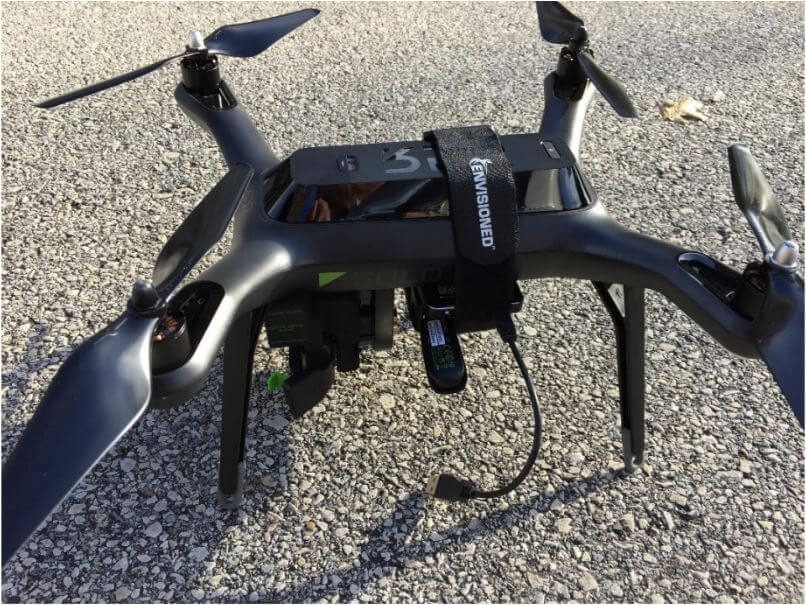
Drone/Rover operations - The agent can be run on systems such as a Raspberry Pi and flown on a drone (it’s made several flights on a Solo 3DR), or attached to a rover in either GUI-controlled or autonomous scan/record modes. And yes, the spectrum output works over this connection as well.
The remote agent is HTTP JSON-based so it can be integrated with other applications
Import/Export - Ability to import and export to/from CSV and JSON for easy integration and revisualization. You can also just run 'iw dev <interface> scan' and save it to a file and import that as well.
Produce Google maps when GPS coordinates are available for both discovered SSID's / Bluetooth devices or to plot the wifi telemetry over time.
Over on YouTube user IW2DZX has uploaded a video showing him using an old EeePC 900 to receive HF with an RTL-SDR V3 running in direct sampling mode on a Raspberry Pi 3 which is running a SpyServer. An EeePC 900 is an old netbook that was released in 2008 which is lightweight, portable and was fairly cheap. Second hand Eeepc's can now be found on eBay for less than $60 US.
By running the RTL-SDR on a Raspberry Pi 3 with SpyServer the need to have the dongle connected to the netbook is eliminated. Instead the radio data from the RTL-SDR is efficiently sent over a network connection and received via the WiFi on the Eeepc.
In his area of Barajas, Spain the meteorological agency recently switched to the newer RS41-SGP radiosondes. To decode these Daniel uses the open source "RS" software which is capable of decoding various radiosondes including RS41. He notes that for now it is better to use his fork of "RS" as the base version contains a bug. He also shows how the received data can be plotted in Viking, which is a program used for plotting things like GPS tracks on a map.
Finally he shows how to feed the radiosonde data to the APRS-IS network. APRS is a packet radio system used by hams which works via radio and the internet, allowing for worldwide communication by radio. Feeding the data into APRS-IS allows anyone to see the flightpath on a site like aprs.fi.
RS41 Radiosonde Flight Path recorded by Daniel Estevez
An antenna rotator can be used to automatically point a high gain directional antenna such as a Yagi at a low earth orbit satellite which passes overhead relatively quickly. Such as antenna can be easily connected to an SDR like the RTL-SDR to receive data such as HRPT weather satellite images from satellites.
Manuel's antenna tracker is inspired by the SatNOGs rotator, but he writes that his one was designed to slightly to be smaller and more powerful. For the driving motors he uses NEMA23 steppers which are mounted in a frame made out of 2020 aluminum extrusions. An Arduino Nano with optical end stops controls two TB6600 stepper drivers which control the motors. The rest of the parts such as brackets and gears are all 3D printed.
Attached to the antenna rotator is Manuel's home made carbon Yagi antenna. He also attempted to use his 1.2m dish but found that the rotator could not handle the weight.
Moments ago we posted our own review of the RSP1A. But other radio bloggers, YouTubers and websites have also recently released reviews. Below is a summary of those other reviews.
But what of this SDR’s performance? In a nutshell: as of today, I’d contend that the RSP1A will simply be the best SDR value on the market. End of story. There is nothing I know in the $99 price bracket that can beat it.
NN4F.com
In his post NNF gives a quick review of the new unit from the perspective of an average user. He notes that spurious signals that were visible on HF with the RSP1 as now gone, at that the RSP1A is on par with the RSP2, if not better.
HamRadioScience
Here the author of hamradioscience.com compares his RSP1A with the RSP1 and RSP2. He notes better sensitivity with the RSP1A compared to the RSP1, but comparable performance with the RSP1A vs the RSP2. He has also uploaded a video demonstrating a comparison between the RSP1 and RSP1A.
RSP1A First Look
Laboenligne.ca
Over on YouTube user Laboenligne.ca (aka Pascal Villeneuve VA2PV) has uploaded an interview that he did with Jon Hudson of SDRplay. The interview discusses the RSP1A product as well as the development around it.
NEW SDRplay RSP1A 14 bit SDR receiver - Interview with Jon Hudson
Yesterday the SDRplay team released the $99 US RSP1A, which is a revision of the RSP1A. In this post we present a review comparing its performance against the older RSP1 and the currently selling $169.95 US RSP2. We aim to mainly show demonstrations of improvements that we've found on the RSP1A in areas where we discovered problems on the RSP1 or RSP2.
Discussion of Improvements
First we present a discussion on the improvements made.
TCXO: The first noticeable improvement is that the RSP1A now comes with a 0.5PPM TCXO. This was one of the main criticisms of the RSP1 as the RSP1 only came with a standard oscillator which can drift as the temperature changes. But as mentioned in our previous review that included the RSP1, the drift was fairly small after warmup due to the good heat dissipation of the large PCB, and the relatively low power usage and thus less heating of the Mirics chips used on RSP units. Nevertheless, a TCXO is a good upgrade and brings it back in line with most low cost SDRs on the market now.
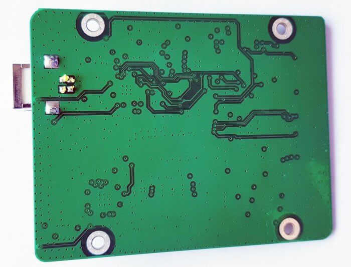
Enhanced RF Preselectors + Notches: Strong out of band signals can overload an SDR causing problems like imaging and reduced sensitivity. Preselectors are RF filters which help to filter out unwanted signals for the band that you are listening to.
The RSP1 had 8 preselector bands and the RSP1A brings this number up to 12, which is even more than the 10 preselectors on the RSP2.
In testing we found that the new preselectors certainly do help out a lot. The new 2 MHz low pass and 2 - 12 MHz certainly help to reduce interference from the MW broadcast AM band. Changes in the VHF filters reduce problems from strong broadcast FM and DAB stations. The filters have also been sharpened considerably making the existing filters even more effective. The RSP-1 in some cases suffered quite severely from out of band signal interference, and the RSP-2 made it a bit better, but the RSP-1A solves the interference problem much more.
The new FM/AM and DAB notch filters also do a good job at notching out these often problematic very strong signals.
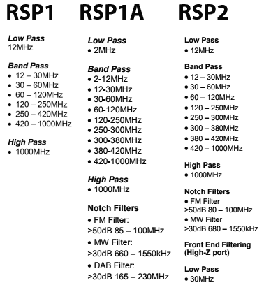
Preselectors on the RSP1, RSP1A and RSP2
Improved LNA Architecture: In the RSP1 the front end LNA could only be turned on or off. Turning it on reduces the noise figure and improves performance, especially at UHF frequencies. The single gain step was problematic as often the LNA could overload on strong signals if turned on. The RSP1A introduces a gain control block which allows the LNA to have variable gain steps.
This new architecture helps to maximise the dynamic range of the RSP1A, thus reducing overloading.
Extended frequency coverage down to 1kHz: The lower limit of the RSP1 was 10 kHz, so really low LF reception is now available on the RSP1A.
Bias-T: Just like with the RSP2, the bias-t allows you to power external devices over the coax cable. Such as remote LNAs, switches etc. Running a good LNA next to the antenna is optimal, as this helps push signals through the coax cable losses.
RF Shielding: Like the RSP2 the plastic case is now spray painted with metallic paint on the inside. This works almost as well as a full metal case to shield from unwanted signals entering directly through the PCB, instead of through the antenna. We do still notice some leakage making its way in through the coax shield, but it is relatively minor with the shielding.
ADC Resolution Increased to 14-bits: The RSP1A uses the same ADC chip as the RSP1, but now has unlocked 14-bit ADC capability for bandwidths below 6 MHz thanks to onboard decimation and oversampling. So now 14-bit data comes directly into the PC if using a bandwidth below 6 MHz. Further decimation can still be achieved within software like SDRuno.
A higher bit ADC can improve dynamic range, meaning that strong signals are less likely to overload the SDR.
We asked SDRplay how 14-bits was achieved with the same chips used by the RSP1 and they explained that it is through oversampling and decimation onboard the chip. They also wrote the following technical reply which is a very good read (collapsed as the reply is quite long, click on "Read the Reply" to expand):
[expand title = "READ THE REPLY"]
The ADCs on the MSi2500 use a sigma-delta topology where a highly oversampled multi-bit ADC uses decimation filtering to provide the desired resolution. As the original spec for the MSi2500 called for 12 bit resolution, the fact that the converter was capable of delivering 14 bits for final sample rates of less than 6.048 MHz was ignored. Working with the Mirics team, we have been able to unlock the extra two bits of resolution that the MSi2500 was always capable of delivering. Using sample rates above 6.048 MHz, the ADC defaults back to 12 bit resolution.
They also explained:
If we take an 8 bit ADC for example, we can expect around 48 dB of instantaneous dynamic range. This will most likely be far lower than that achievable from the RF front end whose dynamic range will be influenced by factors such as noise figure, intermodualtion, cross modulation and synthesizer phase noise (reciprocal mixing). A decent tuner front end should be capable of delivering 65-70 dB of instantaneous dynamic range, which is also roughly what you can expect from a 12 bit ADC. In other words, we believe that in the RSP1, the instantaneous dynamic range of the tuner and ADCs were approximately the same. The limitation that the RSP1 had was because of the single gain step in the LNA, it was not always possible to utilise the available dynamic range in the most effective way. The RSP1A gives much greater (and finer) control over the RF gain and this allows for better alignment of the signal level into the tuner to better exploit the available dynamic range. In our tests in the broadcast FM band, we believe that the RSP1A gives around 10 dB more ‘usable’ dynamic range than the RSP1. In other words, if we combine multiple controlled modulated signals (for RF signal generators), with real weak off-air signals, the RSP1A is capable of handling interferers that are around 10 dB greater than the RSP1. Benchmarking against other products, in our tests, the RSP1A seems to give better performance now than anything else in the same price range, both in terms of sensitivity and in terms of in-band overload performance.
The RSP1 always gave very good sensitivity but in optimising it in this way, we gave up some performance in terms of in-band overload performance. Our objective with the RSP1A was to address this without sacrificing sensitivity.
Now, going back to the issue of 14 bits vs 12 bits and instantaneous dynamic range. If we increase the ADC dynamic range from 12 to 14 bits, then the ADC dynamic range should no longer influence the performance of the receiver. Indeed, it is our view, that for any receiver that needs to use a tuner as part of the front end (and any receiver that operates across the frequency range of the RSP will have to use a tuner for the foreseeable future), there is little benefit to be gained with ADC resolutions in excess of 14 bits, as to utilise the extra dynamic range that a higher resolution ADC can give, a much higher performance tuner would be required. Tuner technology has come a very long way in the last 10-15 years and the performance of modern integrated devices is actually very good. To get 12 dB of better dynamic range from a tuner is extremely difficult and can really only be achieved by using very much greater levels of power and esoteric semiconductor technologies. One possible area where you might see better performance is where you have multiple strong interfering signals to the extent that the RF gain needs to be turned down to such a level that the ADC quantisation noise effectively limits the noise floor of the receiver. In this case, you ought to see improved performance in 14 bit mode when compared to 12 bit mode, but please note that the improvement may only be a few dBs in the weak signal reception. If the noise floor of the receiver is still limited by the external LNA, then improved ADC dynamic range will give no perceptible improvement whatsoever.
A direct sampling receiver that does not use a tuner should in principle allow greater dynamic range than one that does, but in practice any direct sampling ADC needs some form of external low noise amplification to ensure a reasonable noise figure and the dynamic range (noise, intermodulation performance etc) of this external amplification block becomes a limiting factor. This is certainly true at VHF and above. At HF, as you will be well aware, the receiver noise figure is not really very important because the atmospheric noise floor is so high. In principle, you might therefore think that our best approach would be to bypass the tuner and use the decimated 16 bit performance of our ADCs. This would still give an effective receiver bandwidth of 375 kHz with 16 bit performance. The reality though is that the real dynamic range of signals coming into the antenna is limited by propagation conditions and atmospheric noise. It is rare to find signals that are above the atmospheric noise floor that vary by more than 60 dB. In practical terms, we believe that equivalent performance can be achieved, simply by the addition of RF pre-selection and AM-band notch filters and in this way we avoid some of the other compromises of direct sampling systems.
So, in a nutshell, when transitioning from 12bit mode to 14 bit mode, don’t expect to see 12 dB more dynamic range. In the real world, it doesn’t work this way. This is why 12 bit devices can give quite favourable performance to higher end 16 bit SDRs such as the Elad FDM-S2, particularly when you consider the difference in cost. We fully expect the Elad to be better, but the difference will not be 24 dB or anything close to it.
Without wishing to labour the point about myths and misunderstandings, it is worth adding a bit of clarification regarding the term ‘dynamic range’. This is a much misunderstood term which can mean very different things depending upon the circumstances and type of signal being received. There is also a difference between ‘dynamic range’ and ‘instantaneous dynamic range’. If you ask 10 different radio engineers what they mean by the term dynamic range, you are sure to get more than one different answer! Another important point to note is that ADC dynamic range is NOT the same as receiver dynamic range. When referring to ADCs, the term dynamic range generally refers to the Spurious Free Dynamic Range (SFDR). This is measured using a CW tone and refers to the ratio between the maximum RMS signal that the ADC can handle and the largest spur or level or quantisation noise within the ADC bandwidth. This is a measure of both noise and linearity of an ADC. As a case in point, it is worth noting that a 16 bit ADC may not necessarily have a higher SFDR than a 12 bit ADC despite having a greater resolution. The greater resolution will generally result in a lower level of quantisation noise, but not necessarily a lower level of harmonic distortion and spurs. In a multi-channel/multi-signal SDR system a lower level of quantisation noise is generally helpful, even if the SFDR is not better, but is not guaranteed to give better performance if the weak signal of interest happens to fall on top of an ADC spur. Where a single signal occupies the entire ADC bandwidth, it is ONLY the SFDR that matters and not the resolution or quantisation noise. Sometimes you will hear people refer to the Effective Number Of Bits ENOB. ENOB is related to the SFDR in that it is a measure of the maximum SINAD that can be attained with an ADC at a give sample rate and so is also a measure of both linearity and noise performance. ENOB is actually = (SINAD – 1.76)/6.02 In the ADC subsystem used in the RSP, whilst the ADCs are 12 bit at 8 MHz sampling the ENOB is 10.4 (for both I and Q). At lower sample rates, the ENOB improves and gets closer to the idealised performance of the converter.
In a receiver system as a whole, the term dynamic range will generally be interpreted to mean the difference (in dB) between the minimum discernible signal and the maximum level of signal that can be handled. But this is different from the term instantaneous dynamic range, which generally refers to the difference between the minimum discernible signal in the presence of the largest signal that can be handled at the same time. What this ‘number’ is in each case will depend upon the type of signal. So for example, a receiver with a given noise figure and linearity performance will have a different instantaneous dynamic range when receiving a 8 MHz wide 256-QAM CATV signal than when receiving a FM signal that is a few kHz wide. This is simply because the SINR (Signal to Interference + Noise Ratio) requirement for a given BER for a 256-QAM signal is very different than that required for a FM signal and also the peak to average ratio of the two signals is very different.
[/expand]
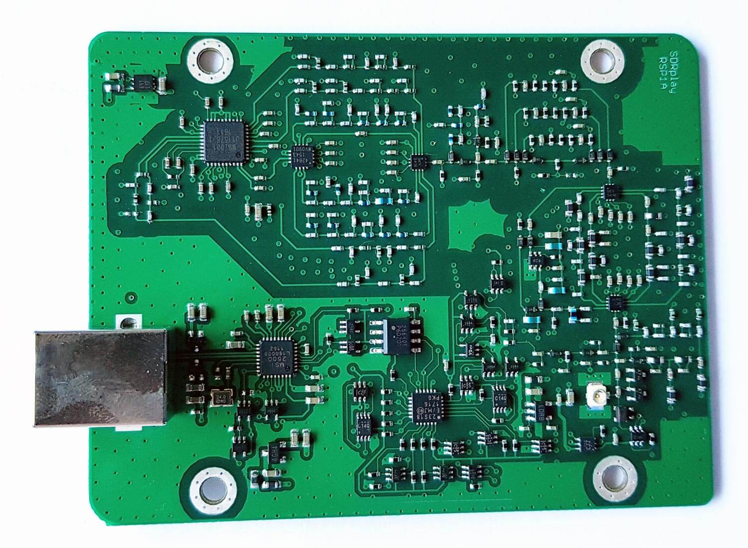
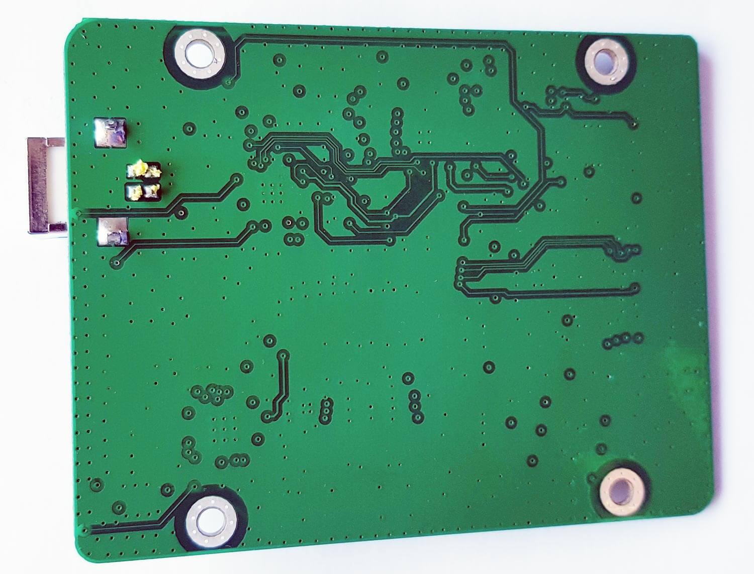
PCB Photos
Compared to the RSP1 the RSP1A PCB is significantly more populated due to the additional filter banks.
Testing the RSP1A
Below we show some screenshots of tests that we made to compare the three RSP units. We focused on bands where the RSP1 or RSP2 had issues, and try to show how much improvement you can get from the RSP1A.
Medium Wave Broadcast AM Band
In the screenshots below we compare the three SDRs on the broadcast AM band which has some very strong signals. The RSP1 definitely shows signals of overloading and turning the gain down did not reduce the interference shown between 0 - 500 kHz.
The RSP1A on the other hand does not overload that easily. In the third screenshot we turn the MW notch on half way through the waterfall. The notch does not cover the entire AM band and signals at around 500 - 700 kHz are attenuated less. But turning it on does seem to do enough to solve most imaging problems as will be seen in the next tests.

![[EN subs] DIY AZ/EL Antennen Rotor / Sat Tracker](https://www.rtl-sdr.com/wp-content/plugins/wp-youtube-lyte/lyteCache.php?origThumbUrl=https%3A%2F%2Fi.ytimg.com%2Fvi%2FIhUJTr5AOW4%2F0.jpg)