Using National Weather Service Stations for Forward Scatter Meteor Detection

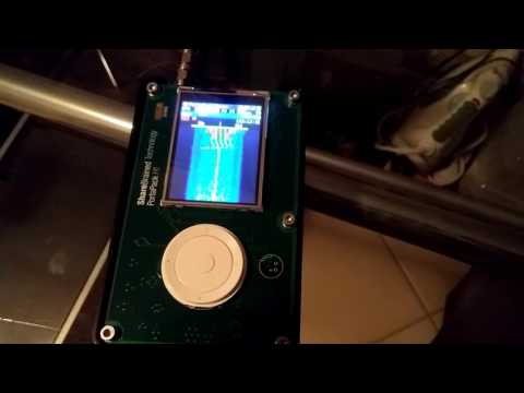
Over on his blog Dave Venne has been documenting his attempts at using National Weather Service (NWS) broadcasts for forward scatter meteor detection with an RTL-SDR. Forward scatter meteor detection is a passive method for detecting meteors as they enter the atmosphere. When a meteor enters the atmosphere it leaves behind a trail of highly RF reflective ionized air. This ionized air can reflect far away signals from strong transmitters directly into your receiving antenna, thus detecting a meteor.

Typically signals from analog TV and broadcast FM stations are preferred as they are near the optimal frequency for reflection of the ionized trails. However, Dave lives in an area where the broadcast FM spectrum is completely saturated with signals, leaving no empty frequencies to detect meteors. Instead Dave decided to try and use NWS signals at 160 MHz. In the USA there are seven frequencies for NWS and they are physically spaced out so that normally only one transmitter can be heard. Thus tuning to a far away station should produce nothing but static unless a meteor is reflecting its signal. Dave however does note that the 160 MHz frequency is less than optimal for detection and you can expect about 14 dB less reflected signal from meteors.

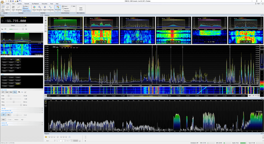
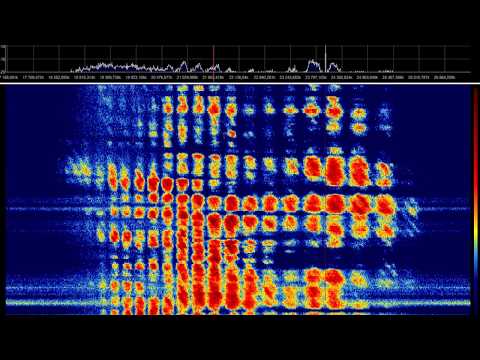
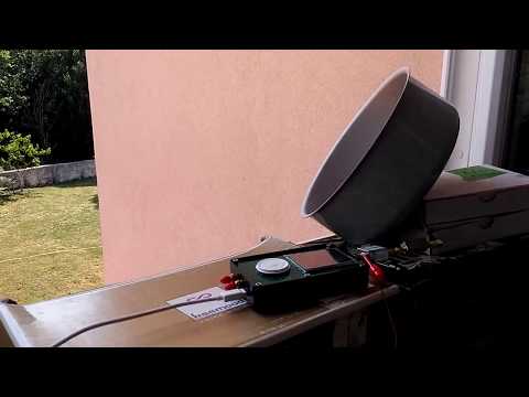
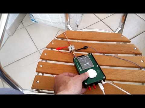
So far Dave has been able to detect several ‘blips’ with his cross-dipole antenna, RTL-SDR and SDR#. He also uses the Chronolapse freeware software to perform timelapse screenshots of the SDR# waterfall, so that the waterfall can be reviewed later. Unfortunately, most of the blips appear to have been aircraft as they seem to coincide with local air activity, and exhibit a Doppler shift characteristic that is typical of aircraft. He notes that the idea may still work for others who do not live near an airport.

A possible meteor detection in SDR#.
Aircraft detection doppler

We note that if you are interested in detecting aircraft via passive forward scatter and their Doppler patterns, then this previous post on just that may interest you.

Talking to Ghosts with an RTL-SDR Dongle

Back in November of last year we posted about Doug Haber’s gqrx-ghostbox which is software that turns your RTL-SDR into an electronic voice phenomenon (EVP) tool, or in other words a ‘ghost box’ or ‘spirit box’. A ghost box is essentially a device that rapidly tunes between broadcast radio stations, creating mismashed audio of multiple stations. Paranormal researchers believe that such a tool can be used to communicate with ghosts or spirits. Over on Amazon commercial ghost boxes/spirit boxes seem to retail for anywhere from $70 USD to $140 USD so an RTL-SDR can be a budget way to get into paranormal research.

Over on her blog paranormal investigator shielaaliens has uploaded a post and video demonstrating an RTL-SDR based ghost box in action. Sheila actually doesn’t use the grqx-ghostbox software, but instead she just uses SDR# with a frequency scanner plugin set to rapidly scan through the broadcast band. In the video she asks the SDR# ghost box a few control questions such as “can you say kitty cat” and “can you say Nantucket”. In response the SDR# ghost box appears to respond with those exact words. Her Facebook post with the video can be found here.

Of course this might all sound pretty far fetched for most readers of this blog, but it is an application that the RTL-SDR is now being used for nonetheless!

Software Defined Radio (SDR) Ghost BOX

SDR-Console V3 Latest Update: Signal History & Receiver Panes

SDR-Console is a popular RTL-SDR compatible multi purpose SDR software package which is similar to programs like SDR#, HDSDR and SDRuno. Currently SDR-Console V2 is the stable version and SDR-Console V3 is in a beta state. A few days ago SDR-Console V3 Preview 6 was released. It comes with some very interesting new features including a built in Airspy server, a recording scheduler, a new feature called signal history and a new receivers pane.

Over on his blog Nils Schiffhauer (DK8OK) has been reviewing the new release of SDR-Conosle V3 and writes the following information about some of the new features:

  • “Signal History” takes the signal strength of the given bandwidth each 50 milliseconds, which can be saved in a CSV file. It is also shown in three different speeds on a display.
  • “Receivers’ Pane” shows up to six combos of spectrum/spectrogram of the complete up to 24 parallel demodulators (they additionally can be shown in the Matrix, as in former versions).

“Signal History” offers many applications, to name just three:

  • analyze fading and its structure with an unsurpassed time resolution of 50 ms
  • document fade-in and fade out
  • measure signal-to-noise ratio of signals

In addition Nils has also uploaded a very useful 19 page PDF where he writes step by step instructions and shows numerous examples of the new signal history tool.

DK8OK's SDR-Console V3 P6 Screenshot. Showing multiple receiver panes and the new signal history feature.
DK8OK’s SDR-Console V3 P6 Screenshot. Showing multiple receiver panes and the new signal history feature.
DK8OK's screenshot of the signal history toolbox.
DK8OK’s screenshot of the signal history toolbox.

Receiving Jupiter Noise Bursts with an SDRplay RSP1

Over on YouTube user MaskitolSAE has uploaded a video showing him receiving some noise bursts from Jupiter with his SDRplay RSP1. The planet Jupiter is known to emit bursts of noise via natural ‘radio lasers’ powered partly by the planets interaction with the electrically conductive gases emitted by Io, one of the the planets moons. When Jupiter is high in the sky and the Earth passes through one of these radio lasers the noise bursts can be received on Earth quite easily with an appropriate antenna 

In his video MaskitolSAE shows the 10 MHz of waterfall and audio from some Jupiter noise bursts received with his SDRplay RSP1 at 22119 kHz. According to the YouTube description, it appears that he is using the UTR-2 radio telescope which is a large Ukrainian radio telescope installation that consists of an array of 2040 dipoles. A professional radio telescope installation is not required to receive the Jupiter bursts (a backyard dipole tuned to ~20 MHz will work), but the professional radio telescope does get some really nice strong bursts as seen in the video.

Jupiter 2017.02.04 RSP 1 UTR-2

The UTR-2 Radio Telescope. Photo Attr. Oleksii Tovpyha (Link)

Receiving NOAA 19 HRPT with a HackRF, LNA4All and Cooking Pot Antenna

Over on his YouTube channel Adam 9A4QV has uploaded a video that shows him receiving the NOAA 19 HRPT signal at 1698 MHz with his HackRF, LNA4ALL and the simple circularly polarized cooking pot antenna that we saw in his last videos.

HRPT stands for High Resolution Picture Transmission and is a digital protocol that is used on some satellites to transmit much higher resolution weather images when compared to the APT signal that most people are familiar with receiving. The HRPT signal is available on NOAA19, which also transmits APT. However, unlike APT which is at 137 MHz, HRPT is at 1698 MHz, and is typically a much weaker signal requiring a higher gain motorized tracking antenna.

However in the video Adam shows that a simple cooking pot antenna used indoors is enough to receive the signal (weakly). The signal is probably not strong enough to achieve a decoded image, but perhaps some tweaks might improve the result.

Over on his Reddit thread about the video Adam mentions that a 90cm dish, with a proper feed and two LNA4ALLs should be able to receive the HRPT signal easily. User devnulling also gives some very useful comments on how the software side could be set up if you were able to achieve a high enough SNR.

GNU Radio has HRPT blocks in the main tree (gr-noaa) that work well for decoding and then David Taylor has HRPT reader which will generate an image from the decode GR output. http://www.satsignal.eu/software/hrpt.htm

http://usa-satcom.com has a paid HRPT decoder that runs on windows that has some improvements for lower SNR locking and works very well.

– devnulling

On a previous post we showed @uhf_satcom‘s HRPT results where he used a motorized tracking L-band antenna and HackRF to receive the signal. Some HRPT image examples can be found in that post.

NOAA-19 HRPT 1698MHz with HackRF + LNA4ALL + Pot antenna

New Raspberry Pi image preloaded with software available for the SDRplay

Over on their forums the SDRplay team have just released a new Raspberry Pi image which comes preloaded with the drivers and a bunch of ready to use software. They write

We have released a Raspberry Pi 3 image that has a number of SDR applications pre-built and tested that support the RSP. Periodically, we will update the image with software updates and new software.

The current list of software included on the image is:

SoapySDR/SoapySDRPlay, SoapyRemote, ADS-B (dump1090), CubicSDR and SDR-J DAB receiver

Please note: This is a complete OS with software image. Writing the image to a micro SD card will wipe the micro SD card of any other data that is on there, so we recommend you make sure you have backed up any data on your existing micro SD card or you use a new micro SD card.

Instructions:

1. Download image. There are two downloads provided, the 7zip version is just a smaller download but not everyone has 7zip which is why we also provide a zip download. The links are here:

http://www.sdrplay.com/software/SDRplay_RPi3_V0.1.zip (2.7 GB)

http://www.sdrplay.com/software/SDRplay … 0.1.img.7z (2.0 GB)

2. Extract the contents of the compressed file. This will extract to a .img file which will be about 7.2 GB

3. Use an image writer such as Win32DiskImager (https://sourceforge.net/projects/win32diskimager) to put the image onto the micro SD card.
WARNING: Please make sure that you use the correct drive letter for the micro SD card. The image writing software will completely remove any data that is on the destination media.

That’s it – put the micro SD card into the Raspberry Pi 3 micro SD card slot and boot the system. Allow the system to fully boot and you will see a GUI that will allow you to run each of the applications or read further information.

We also recommend that you use an active cooling system on your Raspberry Pi 3 to avoid any issues with over heating. In our tests, we have used heatsinks and a fan in a case. The CPU speed will be throttled if the temperature gets too hot, so for optimum use this is really recommended. These cases are available at reasonable prices from many Raspberry Pi stores.

If you are a developer of software that supports the RSP and you would like to be included on the image that we will release periodically, please contact us at [email protected] – currently we’re aiming to update the image every quarter, this will largely depend on software availability and what the demand is.

We are aware of other software that we are looking to get onto the next release such as Pothos and more SDR-J software. We will work with developers on any issues we’ve seen during this process so that we can get them onto future images.

Best regards,

SDRplay Support

Last week we posted about Kevin Loughin’s video where he showed how to get CubicSDR and an SDRplay running on a Raspberry Pi 3. This new ready to go image saves you from needing to perform the install process.

Testing the Outernet Dreamcatcher: Linux Based ARM PC with Built in RTL-SDR

Last week we posted about Outernet's new Dreamcatcher unit which is an RTL-SDR + L-band LNA + computing board all on the same PCB. The Dreamcatcher comes with a new active ceramic L-band patch antenna, costs $99 USD (plus shipping) and can be bought directly from their store. Outernet were kind enough to send us a review unit, and we've been testing it for the past few weeks. This post is a review of the unit.

Background

Outernet is a free data service that uses L-band satellites to beam down information like news, weather updates, Wikipedia articles, books and more.

In the past Outernet have used the $9 USD C.H.I.P computing board, an RTL-SDR dongle and an external LNA as the receiving hardware for their data service. However, popularity of the Outernet service has been severely hindered by the huge supply shortages of the C.H.I.P. Over the past year or so it has been almost impossible to get a hold of a C.H.I.P unit if you did not back the Kickstarter or buy one from Outernet's first initial stock. By manufacturing their own PCB including the computing hardware, Outernet must be hoping to be able to control their stock situation, and not rely on third parties who may not be able to deliver.

At the moment the Dreamcatcher can only be run on their new Armbian image. The older Skylark image has been removed from their servers presumably because the Outernet signal is going to change in the near future and the old demodulator on Skylark may no longer work. The Armbian image is basically just standard Armbian and at the moment does not actually run any Outernet software, and cannot decode their signal, but this is being worked on. Eventually they hope to replace Skylark with a standard decoding app that runs on Armbian.

In this post we'll review the Dreamcatcher with Armbian and consider it as a general purpose receiver (not just for Outernet), and we'll also review the new active ceramic patch antenna as well.

Dreamcatcher Overview

The Dreamcatcher is a single PCB that combines an RTL-SDR, Linux (Armbian) based computing hardware, and an L-band LNA and filter. 

On first impressions we noticed that the PCB is relatively large square at about 12 cm by 12 cm. The most prominent chip is the Allwinner A13 SoC. The RTL-SDR circuitry is positioned in the upper right with the RF sections (R820T and LNA) both covered with RF shielding cans. There is no onboard WiFi circuitry, but a small 'EDUP' branded WiFi dongle is included and plugs into one of the USB ports on the PCB.

We measured the Dreamcatcher to be using about 400 mA - 600 mA while idle and 800 mA while utilizing the RTL-SDR and 100% CPU. Heat is not an issue as the Dreamcatcher stays relatively cool during its operation even at 100% CPU with the CPU only getting up to about 45 degrees C.

Continue reading

Testing the HackRF and Portapack with an LNA4ALL

Over on YouTube Adam 9A4QV has been testing out his HackRF and Portapack with his LNA4ALL. The LNA4ALL is able to be powered inline via the bias tee on the HackRF. In the first video Adam shows that the HackRF and LNA4ALL is capable of receiving L-band satellites easily. The antenna he uses is a homemade circularly polarized antenna with a cooking pot being used as the reflector.

HackRF + LNA4ALL RX mode L-band indoor

In the second video Adam shows the HackRF, Portapack and LNA4ALL receiving a telemetry signal on 442 MHz.

HackRF + Portapack + LNA4ALL w/ Bias-t

Finally in the last video Adam shows himself making a full QSO contact using the HackRF, Portapack and LNA4ALL. The software he uses on the Portapack is Furtek’s ‘Havoc’ firmware which has microphone to TX functionality. The LNA4ALL is able to work in transmit mode without trouble. Adam has written instructions for modifying the LNA4ALL so that it can transmit and use the HackRF’s bias tee power at the same time over on his website lna4all.blogspot.com.

HackRF + LNA4ALL making a QSO on 145 MHz