Reverse Engineering a RF Controlled Ceiling Fan with the RTL-SDR

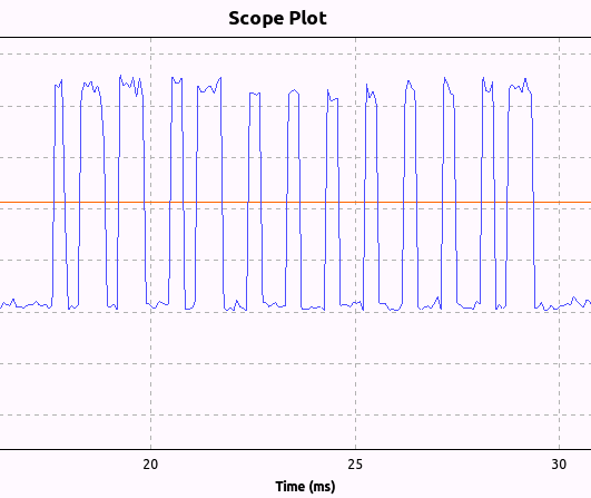
Using an RTL-SDR Clayton Smith was able to reverse engineer his remote controlled ceiling fan. To do this he first used his BladeRF to determine that the remote control was transmitting a signal at 303.747 MHz. He then used a simple GNU Radio flow graph with the RTL-SDR to plot the amplitude of the signal over time which suggested that the signal was using on-off keying. From the plot he was then able to visually determine the bit pattern sent from each button on the ceiling fan remote.

Next he used his bladeRF and another GNU Radio flowgraph to replicate and transmit the the bit pattern which was able to control the ceiling fan from the PC.

Clayton notes that all this reverse engineering was done in half an hour, demonstrating the power of software defined radio.

Ceiling Fan Bit Pattern Recovered with an RTL-SDR and GNU Radio

Direct Sampling Mode with No Hardware Modifcations

Update: There is now a newer driver that allows HF tuning without hardware mods via a different mechanism. The new mod seems to work better than this one. Read about it at https://www.rtl-sdr.com/new-experimental-r820t-rtl-sdr-driver-tunes-13-mhz-lower/.

Over on the Reddit RTL-SDR forums user Jengal has posted a modified RTLSDR.dll dll file for SDR# which allows the direct sampling mode to be used on the R820T without the need for any hardware modifications. The modified dll is compiled from keenerds experimental branch of the RTL-SDR driver, which uses code for the no hardware mod written by tejeez. The no hardware direct sampling code was inspired by Anonofish’s discovery where he found that the E4000 based RTL-SDR could tune to AM radio without the need for the direct sampling mod (though this appears to be now patched in the newer rtlsdr drivers).

The direct sampling mod is a hardware modification to the RTL-SDR which allows it to receive HF frequencies between 0-14.4 MHz without the need for an upconverter. It works by connecting an antenna directly to the RTL2832U chip, thus bypassing the tuner. Teejez’s modification tells the RTL-SDR to bypass the tuner in software, allowing antennas to be connected to the normal antenna port. HF reception with the experimental driver is very poor in comparison to the direct sampling hardware mod or an upconverter, but even so Jengal was able to receive AM Radio, an SSB ham radio signal and an HF weather report with a simple longwire antenna.

To use the modified dll, simply download it from this link, rename it to rtlsdr.dll, and replace the original rtlsdr.dll in the SDR# folder. Then connect an HF antenna to the normal antenna port and in SDR# tune to a frequency between 0-14.4 MHz. Next turn ON the RTL AGC option in the configure menu. Jengal replaced the function of the RTL AGC option with the direct sampling mod. He found that best reception occurred when he set the gain to 48 dB.

No Hardware Mod Direct Sampling in SDR# Receiving AM Radio

The Effect of Noise Produced by the RTL-SDR

Over on YouTube Adam, the creator of the LNA4ALL, LNA4HF and UP100 upconverter has uploaded a video showing that the noise that is produced by the RTL-SDR dongle itself can degrade performance when combined with an LNA and/or upconverter.

Most commonly we’ve seen people mount the RTL-SDR dongle together with an upconverter and/or LNA in the same shielded box right next to each other. However, these results show that the RTL-SDR should be shielded separately from the LNA and upconverter for best performance.

Unshielded DVB-T dongle may cause the problems

SDR# Now with Noise Blanker

The latest version of SDR# has now been updated to include a noise blanker plugin. A noise blanker can reduce impulsive noises like those created by spark gaps and electric motors. Other SDR programs like Linrad and HDSDR have had noise blanker functions for a while so this is a welcome addition to SDR#. Below is a comparison of the noise blanker turned on and off on a noisy CW signal.

To update SDR# to the latest version simply run install.bat again. Take note that updating will remove any plugins you have added to the SDRSharp.exe.Config file so you may wish to save it first.

Noise Blanker Off

[audio https://www.rtl-sdr.com/wp-content/uploads/2014/03/nb_off.mp3]

Noise Blanker On

[audio https://www.rtl-sdr.com/wp-content/uploads/2014/03/nb_on.mp3]

Receiving Weather RTTY and FAX with the RTL-SDR

YouTube user Tiago Sousa shows how he was able to receive weather Radioteletype (RTTY) data using the RTL-SDR, an upconverter and MultiPSK. Weather RTTY is broadcast by weather services such as the Deutscher Wetterdienst (DWD) which is broadcast from Hamburg, Germany. It is intended for people at sea.

Tiago used an RTL-SDR with upconverter and an 11 meter long wire antenna. For the software he used SDR# and piped the audio to MultiPSK.

Weather RTTY - DWD Hamburg heard in Portugal

Tiago has also uploaded a second video showing him receiving Weatherfax with the same setup. Weatherfax is a signal that transmits a fax image showing weather patterns.

Weather Fax - DWD Hamburg heard in Portugal

SDR# now with IF Stage Noise Reduction Algorithm

SDR# has recently been updated to include an IF stage digital noise reduction algorithm. Previously digital noise reduction could be done at the audio output stage, but now it can be done to the IF signal as well. Performing digital noise reduction on the IF stage appears to work much better than at the audio stage. Update SDR# by running the install.bat file again.

Here are some comparison audio files tested on a noisy NFM voice signal for listening.

Original Signal

[audio https://www.rtl-sdr.com/wp-content/uploads/2014/03/IF_NR_OFF.mp3]

IF Noise Reduction (set to -12 dB)

[audio https://www.rtl-sdr.com/wp-content/uploads/2014/03/IF_NR.mp3]

Audio Noise Reduction (set to -80 dB)

[audio https://www.rtl-sdr.com/wp-content/uploads/2014/03/AF_NR.mp3]
sdrsharp_if_nr
SDR# IF Digital Noise Reduction Plugin

Decoding HOT, EOT & DPU Train Data

On YouTube user Curt Rowlett has uploaded a video showing how he was able to decode HOT, EOT & DPU signals from trains using an RTL-SDR. Head of Train (HOT) and End of Train (EOT) signals are used on trains to transmit telemetry data such as brake line pressure and monitor accidental separation of the train. Distributed Power Unit (DPU) signals are control signals that are used to control remote DPU’s on long trains. DPU’s are locomotives which are placed in the middle or rear of a train to help more evenly distribute pushing and pulling power over the entire train.

Curt used the SoftEOT and SoftDPU software programs to monitor and decode these signals. This software can be downloaded from the softEOT Yahoo! Group after requesting and being accepted into membership.

HOT signals can be found on 452.9375 MHz, EOT signals on 457.9375 MHz and DPU signals on 457.9250 MHz.

Decoding HOT, EOT & DPU Train Data

Ham it up Upconverter 3D Printed Case YouTube Giveaway

Over on YouTube Eric William has posted a video about his competition where he is giving away two 3D printed ham-it-up upconverter cases. The ham-it-up is an upconverter that can be used with the RTL-SDR to allow it to receive HF (0-30 MHz) frequencies. To enter the competition you simply need to go to Erics web forum and post about what you use SDR for in the competition thread. The competition is open only for North American viewers and ends on May 19 2014.