A new TETRA voice and multiframe SDS decoder
Recently Marek Sebera of ITDS Consulting wrote in to let us know about two new TETRA decoders that they have released. TETRA is a trunked radio communications system that stands for “Terrestrial Trunked Radio”. It is used heavily in many parts of the world, except for the USA.
The first piece of software released is called TETRA Listener and is from the Brmlab hackerspace in Prague. They write that Tetra-Listener is a new program (based on osmo-tetra) that can decode unencrypted voice and data traffic. They also write that it is very easy to set up and install since it uses Vagrant, which is a system that can be used to automatically set up a VMWare or VirtualBox Virtual Machine that has everything set up and ready to go. The instructions for using the software can then be found in the readme of the main tetra-listener page on GitHub.
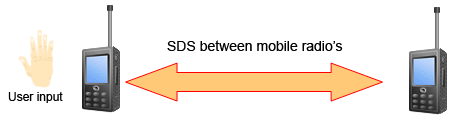
The second software they have written is what they believe is the world’s first open source TETRA Multiframe SDS decoder. SDS stands for short data service and is the TETRA equivalent to SMS text messages used on a GSM network. They write that their solution can assemble long multiframe SDS messages.
Previously we showed how unencrypted TETRA messages could be listened to using telive in our tutorial. It is good to see alternative solutions now coming out, and in the future we hope to test this new software out.