Over on GitHub, user shajen has recently released a new open source program called "sdr-hub," which combines his two prior programs, called rtl-sdr-scanner-cpp and sdr-monitor, into one easy-to-launch project. The result is a powerful RTL-SDR scanner and audio recorder, with a web interface. In the past, we posted about rtl-sdr-scanner-cpp when Tech Minds made a video on it.
The scanner feature allows users to scan for active frequencies across a wide spectrum by rapidly retuning the RTL-SDR. If the transmissions are all within the same instantaneous bandwidth, the user can also record the audio.
The web interface then allows users to easily browse any created spectrum graphs and play back any audio recordings.
The software is available as a Docker image, making it easy to install and run.
SDR-Hub: RTL-SDR Scanner, Recorder and Web UI all in one.
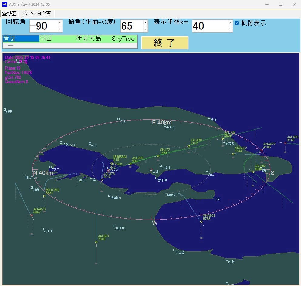
Thank you to Kazuya for submitting an aircraft tracking app that he's created for use with RTL-SDR dongles and dump1090. The program currently exists only as Visual C++ code and is documented in Japanese, so it may be somewhat niche and intended for advanced users to try out. Kazuya writes:
I live near Tokyo Bay, so I enjoy watching the takeoffs and landings at Haneda Airport.
The unique feature of this app is that it visualizes the descent angle, which is difficult to see on a flat map.
This app has not been available for distribution. If you are an intermediate Visual C++ user, you may be able to rebuild or modify the app.
Topographical and landmark information is in text files, allowing you to customize area information in more detail for your airport.
----
(3) Glide_Path Can be built independently.
Execution Environment Copy the folder (ADS_GLIDE_PATH) to C:.
・When using an ADS antenna Install the ADSB antenna and driver software on your PC. (As a mid-way test, you will be able to listen to radio broadcasts on your PC.) Launch dump1090_with_StdinAPL1.bat to ensure that tmp_ADS_B-0000****.txt is continually generated in C:\ADS_GLIDE_PATH\tmpDataFolder.
- Without an ADSB antenna You can use the data in DemoData (approximately 30 minutes, 6,000 entries) to check the software's operation. (Procedure) Launch Glide_Path.exe and, on the parameter change screen, set [S001] Demo Mode to 1. Exit Glide_Path.exe and restart it. The Start Demo button will appear; press it.
(4) Stdin_Apl1 Can be built independently. This is an auxiliary program when using the ADS antenna described above in (3). Stdin_Apl1.exe This program parses the standard output of dump1090.exe, provided by the ADS antenna manufacturer, into a text file and processes the data so that it can be read by Glide_Path.exe.
Thank you to SignalsEverywhere, aka Sarah Rose, for writing in and sharing some updates on what she's been working on recently.
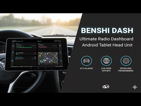
First, Sarah provides an updated video that shows off her Benshi Dash Android application (GithHub, Name-Your-Price Store Download) for VR N76, UV Pro, and other similar handheld radios with Bluetooth connectivity.
Benshi Dash | The Ultimate Radio Dashboard for VR-N76 UV-PRO Etc
Next, she notes that she uploaded a video showing the power of Google's Gemini AI, and how she was able to use it to vibe code a HackRF TV transmitter program on Linux in just a few minutes.
Vibe Coding a TV Transmitter on Linux with a HackRF
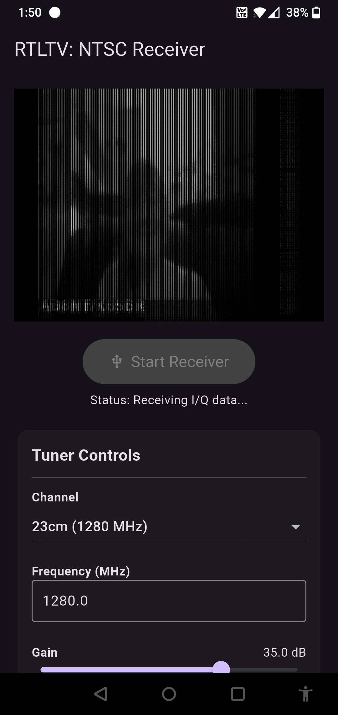
Next, she mentions that she also built an RTL-SDR NTSC Receiver for Android, based on the TVSharp decoder. It is available on GitHub and via her name-your-price store, with a $0.00 minimum spend.
RTL-TV. An NTSC video decoder for Android and RTL-SDR.
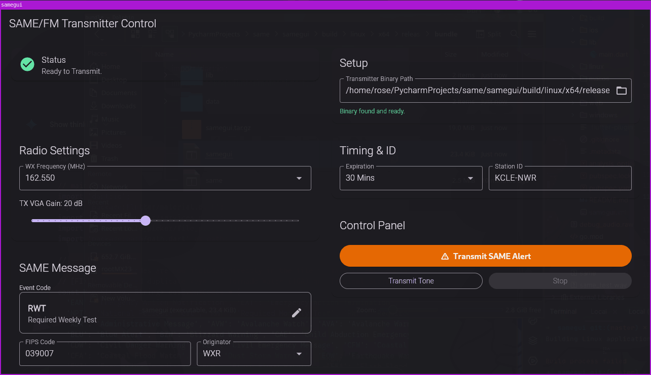
Finally, Sarah writes that she has also created a NOAA SAME weather encoder for use with a HackRF on Linux or Android. This allows users to transmit NOAA SAME (Specific Area Message Encoding) alerts, which are weather alerts typically transmitted on the NOAA Weather Radio frequency, transmitted around 162 MHz. The software is available via GitHub, or via her store for $10 (Linux edition / Android edition).
Thank you to Chris Gianakopoulos for writing in and sharing with us the release of his open-source software-based Automatic Gain Control (AGC) library written in C. The library is hardware agnostic and designed to make it easy for programmers to implement an AGC algorithm into their programs. The AGC library can help automatically optimize the signal-to-noise-ratio (SNR) on SDRs with variable-gain amplifiers (VGA). Chris explains:
I converted my software AGC to C code with the following enhancements:
1. It is radio-agnostic. 2. Itis written in C so that both, C and C++ apps can use it. 3. The app provides two callback functions: one to provide the current amplifier gain setting and one to set the amplifier gain. 4. A signal magnitude is provided as input to the AGC algorithm 5. Among other things,the number of bits to represent the signal magnitude, at init time.
An Automatic Gain Control (AGC) is a feeback system that adjusts the gain of a variable-gain amplifier (VGA) to maintain an operating point such as a voltage magnitude level, current magnitude level, or in the case of a digital radio, the magnitude of signal samples presented to the AGC. Typically, an average magnitude of a block of data is used to perform a smoothing action to the input provided to the AGC.
An attempt was made to make an accurate implementation of what was described in the paper (by Fred Harris and Gregory Smith) in the doc/papers/ directory. For details on design and implementation, refer to that paper.
He goes on to mention why a software AGC is useful:
My motivation for creating an AGC was to give people the ability to run SDR software on radios which conain A/D converters that produce 8-bit output samples. With a 48dB (theoretically, ignoring implementation loss), you don't have much to work with in a radio environment with radically different signal strengths.
With an amplifier, whose output drives an A/D converter, on the rtl-sdr, when I listened to aircraft frequencies, I would hear strong tones when a strong signal would be received. The solution was to reduce the LNA and mixer gains.
I asked myself, why would I want to reduce front-end sensitivity when signal overload was not occuring at the variable gain amplifer input? It was A/D converter overload!
With an AGC, the user can establish a safe operating point that allows enough headroom to avoid overload when a strong signal arrives. When the signal goes away, the gain is increased so that you can hear weak signals.
Hopefully, developers of SDR software will see this and implement it into their software!
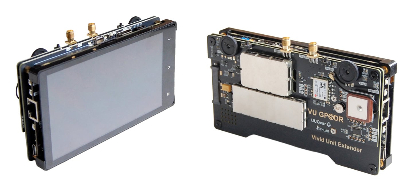
As mentioned in a previous post last week, UUGear have recently released their VU GPSDR expansion board for their Vivid Unit single board computer with touchscreen. Together, this combination results in a handheld Linux system, with built-in RTL-SDR and upconverter.
The VU GPSDR has some interesting features, including:
GPS-assisted 24 MHz clock for improved frequency accuracy and stability
An integrated 108 MHz up-converter for HF (under 30 MHz) reception
Dual programmable rotary encoders for tactile control
A software-controlled frequency output port for experiments
Software features, including OpenStreetMap integration and ADS-B aircraft tracking
Vivid Unit with VU Extender and VU GPSDR
Assembly
We won't repeat the assembly steps as the instructions show everything clearly, but we can say that the assembly steps were clear, and the assembly itself was easy. It was simply a case of plugging in a few jumper wires between the Vivid Unit and VU Extender board, screwing down the extender board, and then slotting in the VU GPSDR into the Extender boards mini-PCIe slot, before finally screwing down the GPSDR. Assembly took less than 10 minutes.
Physical Design Review
The system is put together like a sandwich. You have the screen and Vivid Unit on the top, then the Extender board, and finally the VU GPSDR on the bottom.
The Vivid Unit and GPSDR are essentially bare PCBs that connect to one another via the PCIe slot on the Vivid Extender board. This means that there is no enclosure, and you are essentially handling PCB parts in their raw form. In the future, we would like to see an optional enclosure to protect the unit better.
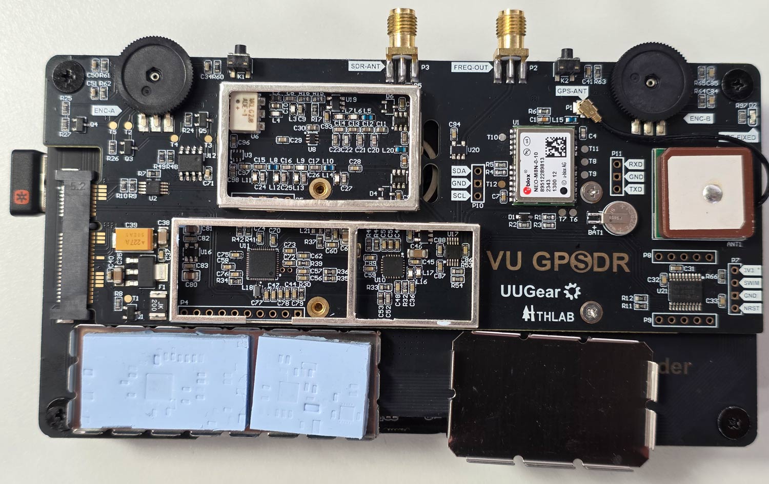
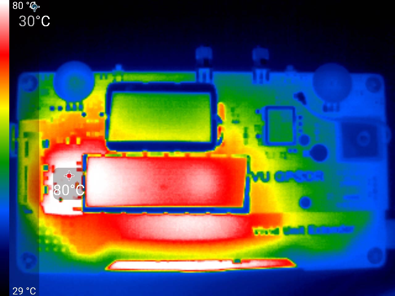
The exposed design results in some flaws that we have to point out. The shielding cans on the VU GPSSDR unit sit on the rear of the system, and during operation, they get very hot to the touch. So much so that handling the unit requires a bit of care to avoid the hot spots. Most of the heat appears to be coming from the AMS1117 LDO on the rear, which gets up to 80 °C, so be careful not to touch it accidentally. From the photos you can see that the RTL2832U and R860 are heatsunk to the shield. This is a good idea to keep the chips cool, but it also means that the metal gets quite hot to the touch. So handling the unit only from the edges is recommended.
Vivid Unit with the shielding cans removed.VU GPSDR Thermals
Secondly, because the Vivid Unit does not have a built-in battery, you need to power it separately via its USB-C port on the side. This makes the ergonomics of handling the unit a little trickier as you also have a cable sticking out. UUGear has noted that they are working on an 18650 battery pack, so this issue may be resolved in the future.
Finally, the "GPS" in the GPSDR comes from the fact that there is a GPSDO with a built-in GPS patch antenna on board. When active, a GPSDO provides excellent frequency stability, meaning that signals will be on frequency and will not drift.
But because of how the system is designed, the GPS patch antenna faces the ground when you look at the screen, even though it should face upward to get a clear view of the sky for satellite signals. However, despite this, we were happy to see that even while upside down, the patch antenna was able to receive several GNSS satellites with sufficient strength in order to obtain a fix when used outdoors.
Indoors, of course, no GPS fix is possible. But the uBlox NEO-M8N GPS module used in the GPSDR also has a fallback TCXO, so even without any GPS fix, the frequency accuracy of the system is good. UUGear also noted that the GPSDO automatically activates once a GPS fix is achieved, so no action is needed when you take the unit outdoors.
Realistically, the design issue with the GPS patch doesn't really matter anyway. For most use cases in handheld operation, the built-in TCXO will be sufficient. Any use case requiring extreme GPSDO precision will probably involve the device being mounted upside down and used remotely.
The screen is clear and bright, the two encoder wheels are non-indented and are in a good spot, and so is the SMA antenna port, although the VU Extender's USB-C plug can block the antenna SMA port if a really fat plug is used (normal-sized USB-C plugs fit OK). The screen is large and has a high resolution, making it possible to use the onscreen keyboard. However, it is still a little fiddly for typing and clicking, so we ended up plugging in a small wireless keyboard.
Over on YouTube, we've seen a talk by Mark Jessop that may be interesting to some readers, as it covers Amateur Radio Direction Finding / Fox Hunting with the KrakenSDR, as well as various other radio tools. If you are unaware, KrakenSDR is our 5-channel coherent RTL-SDR based software defined radio system, designed for coherent applications like radio direction finding.
In the talk, Mark explains the amateur radio fox hunting sport, which involves the organizer hiding a transmitter somewhere in a defined area and having participants search for it using just its radio emissions. He goes on to show the different types of antennas, radio systems and vehicle setups participants used.
Mark further explains that on his particular vehicle, he uses a KrakenSDR as the primary receive system. He explains how the KrakenSDR works, how he integrated it into this vehicle and the custom software and LED display that he is using with it.
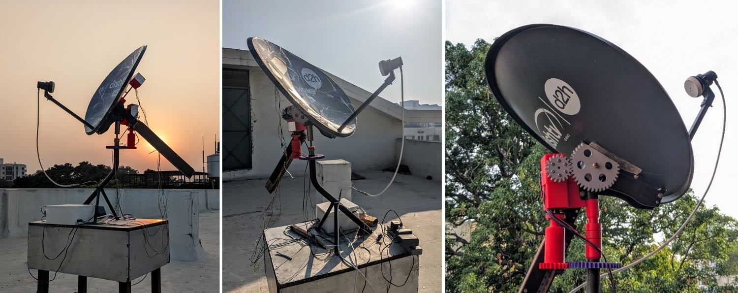
Thank you to Kaustav Bhattacharjee for writing in and submitting to us his project, where he created a small 11.2 GHz motorized radio telescope with a TV dish and an RTL-SDR. A full description of Kaustav's work can be found in a white paper he wrote on behalf of the Department of Physics at the Indian Institute of Technology Roorkee. In summary he writes:
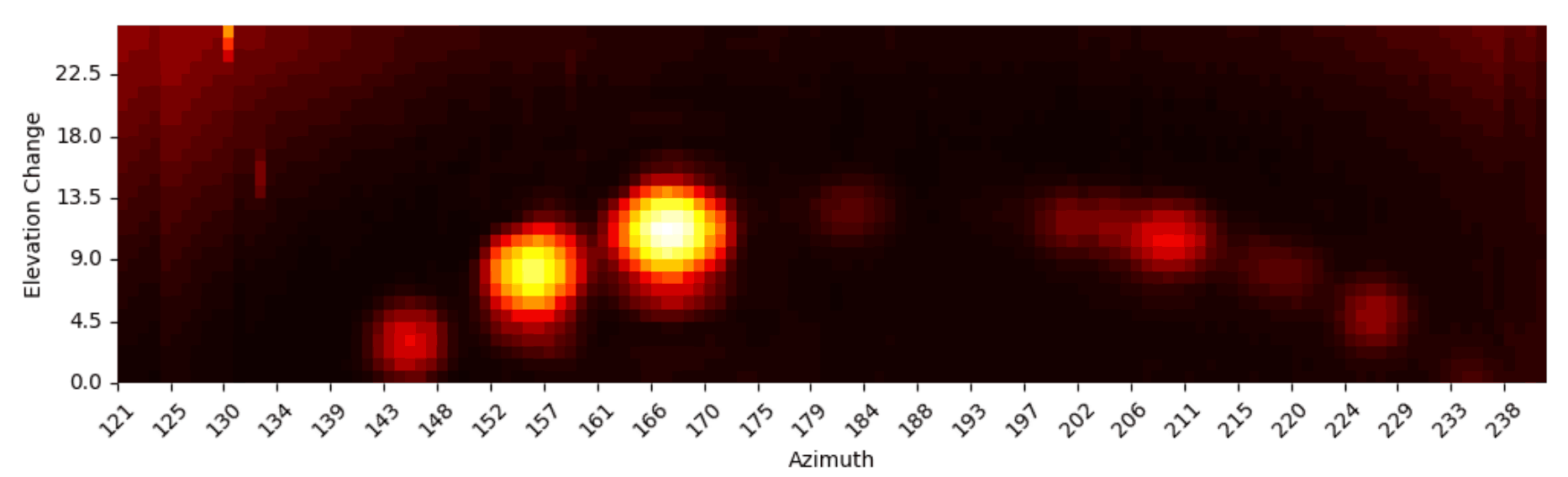
Briefly put, the hardware Setup comprises a 66 cm parabolic dish, a standard Ku-band LNB with bias tee power injection as the frontend, an RTL-SDR V3 tuned to 1.45 GHz (due to downconversion) as the receiver and a Raspberry Pi 5 handling SDR data (via GNU radio) and stepper motor control (using GPIO pins). A heatmap of the southern sky at 0.9° resolution, showing a belt of geostationary satellites, is the primary result of interest!
We also want to point out that his rotor setup involves several 3D printed gears driven by two NEMA17 stepper motors. However, Kaustav notes that the long term resolution is limited due to cumulative backlash errors from the open-loop control scheme.
Kaustav's 11.2 GHz RTL-SDR Radio TelescopeGeostationary satellites visualized with the radio telescope
Thank you to Paul Maine "The SDR Guy" for submitting his latest video showing how to create a simple spectrum analyzer with zoom capability, using an RTL-SDR and GNU Radio. Paul writes:
Zoom capabilities are discussed in the 3rd edition of Richard G Lyons “Understanding Digital Signal Processing” book. This is a novel approach when compared to other YouTube videos about creating a Simple Spectrum Analyzer with an RTL-SDR.
Additionally, in the video, Paul explains what a spectrum analyzer is and what it's used for, as well as explaining the use of attenuators and discone antennas. In the video, Paul uses an RTL-SDR Blog V4, but has mentioned that an RTL-SDR Blog V3 would work well too.
E19 Create a Spectrum Analyzer with Zoom Capabilities