Category: Antennas

Slow Scan Moon Bounce Event for 50th Anniversary of the Moon landing

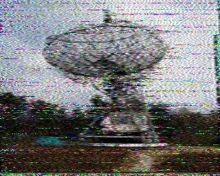
Fifty years ago Neil Armstrong became the first man to step foot on the moon. This weekend on June 20th and 21st 2019 Amateur Radio operators at the [PI9CAM] team have been transmitting Slow-Scan Television images in commemoration of this historic event at the Dwingeloo radio astronomy station in the Netherlands. This station is the oldest rotatable 25-meter radio telescope in the world. 
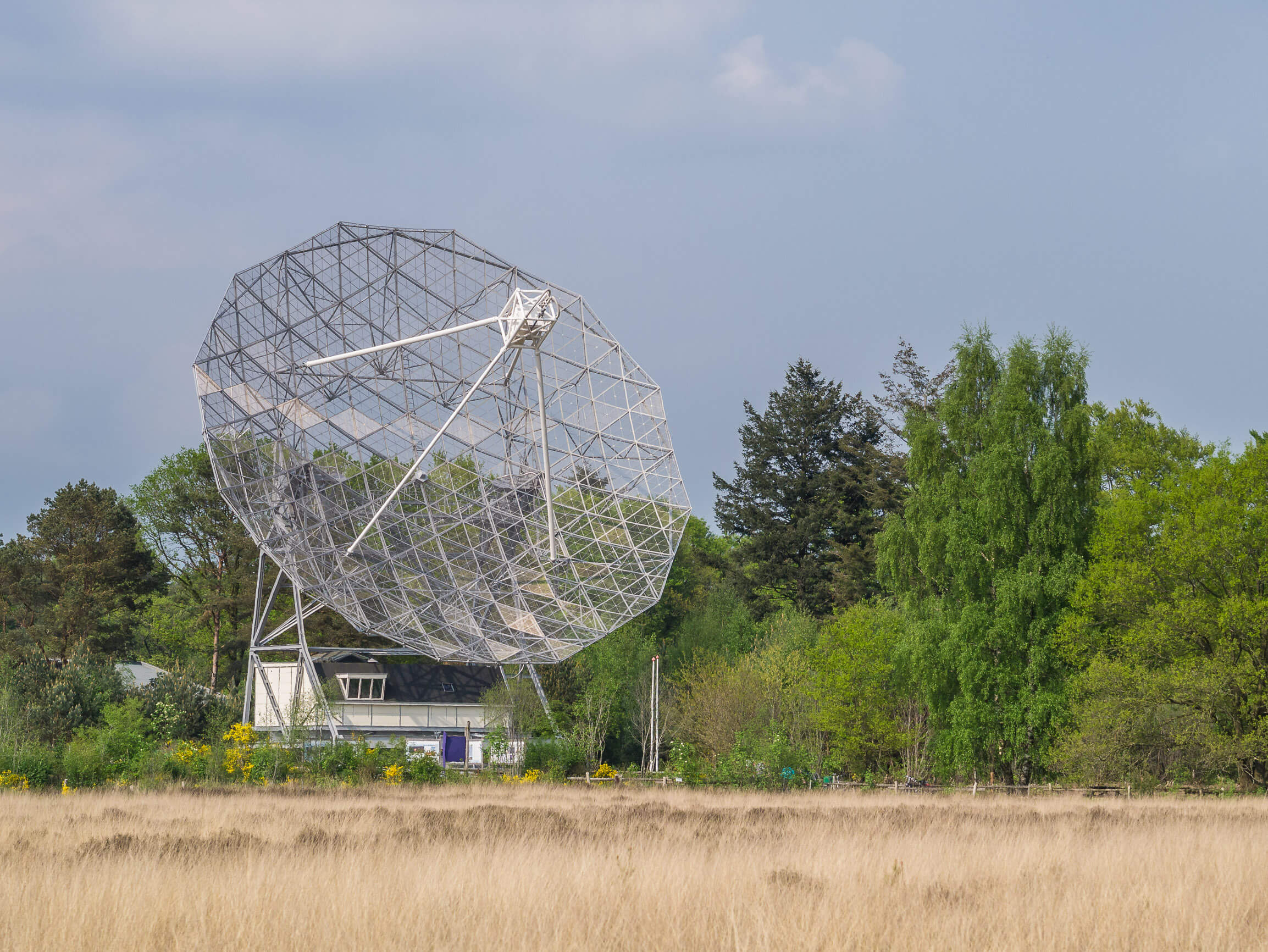
 Dwingeloo radio astronomy station
Dwingeloo radio astronomy station
An EME SSTV Image
An EME SSTV Image

Slow-Scan Television is a method often employed by ham radio operators to send photos over radio waves. You may be familiar with this from some of our previous articles on the SSTV event held by ARISS for the International Space Station.

Station [S1NDP] has previously sent slow-scan EME images between the PI9CAM team and himself. These images can potentially be heard by anyone within line-of-site with the moon during the operation of this event.

The team transmit in the 23cm band at a frequency of 1296.11 MHz, according to the ARRL even a 2.5 to 3meter dish should be enough for reception assuming you have a 23cm feed for your dish. It will be interesting to see what photos are heard by the end of this event.

SignalsEverywhere: Improving HF Reception with Impedance Matching

This week on the SignalsEverywhere YouTube channel host Corrosive explores why impedance matching matters when trying to obtain the best reception possible. To do this he reviews the NooElec 1:9 Balun, which is designed to convert the (roughly) 450 Ohm impedance of a long wire antenna or ladder line dipole back down to 50 Ohms, which is the standard impedance that an SDR expects. Small amounts of impedance mismatch are negligible for RX, but larger mismatches can result in poor reception.

SDR Nooelec 1:9 Balun | Why Impedance Matters in Radio

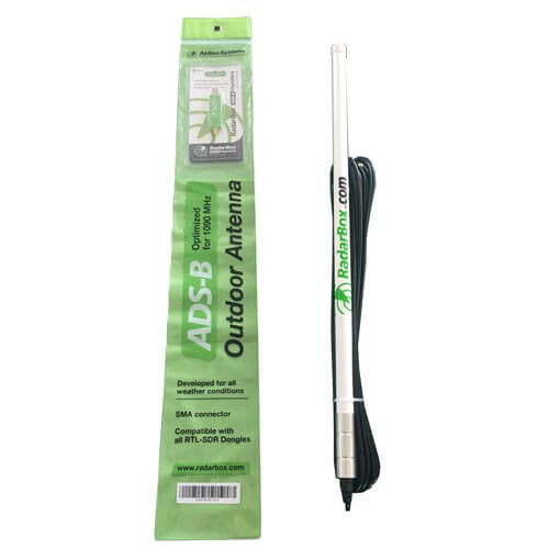
New Products in Store: RadarBox ADS-B Bundle Including Outdoor ADS-B Antenna and ADS-B Optimized RTL-SDR Dongle

A while back we posted about flight tracking company RadarBox.com who had launched their 1090 MHz ADS-B optimized RTL-SDR. Like other ADS-B optimized RTL-SDR's, the dongle contains a 1090 MHz filter and a low noise amplifier that reduces the noise figure, resulting in better SNR, and thus more planes spotted at further distances.

We spoke with RadarBox and asked if they could provide a low cost RTL-SDR + Antenna bundle for us. That bundle is now available in our store for $49.95 + shipping. Shipping takes about 2-3 weeks and costs between $10 - $25 depending on your country. Shipping costs will automatically added to the cart on checkout (please ignore other shipping options and choose free shipping unless you have other items in the cart). Please note that due to the larger size this will be shipped in a cylindrical package from a separate Chinese warehouse, and tracking info will come a few days later in a separate email.

The bundle includes:

  • 1x RadarBox ADS-B 1090 MHz SMA Outdoor Antenna with mounting brackets
  • 1x RadarBox ADS-B Optimized 1090 MHz RTL-SDR

The antenna has 7 dBi gain, 50 (+-5) Ohm impedance, and is made from fiberglass and aluminum. It is fully waterproof and outdoor rated. This is a great set at a great price to get started tracking planes with ADS-B.

To purchase, please click the Add to Cart button below or visit our store at www.rtl-sdr.com/store. Please note we only have limited stock of this product! NOTE: The first shipment of this product will be on July 2nd.

Add to cart
RadarBox Bundle: Includes 1x Outdoor ADS-B Antenna, 1x ADS-B Optimized RTL-SDR


Stratux 1090 MHz + 978 MHz Diplexer Now Available

Recently the company Stratux released a new ADS-B/UAT diplexer PCB. This is useful if you have a single antenna and want to feed two RTL-SDR dongles, with one receiving 1090 MHZ ADS-B and the second receiving 978 MHz UAT. The filter consists of a splitter and two SAW filters.

ADS-B is short for Automatic Dependant Surveillance Broadcast and is used to help track aircraft in the sky. It is transmit at 1090 MHz and the signal contains aircraft data such as the location, speed, altitude and aircraft call sign. ADS-B is utilized worldwide.

UAT is short for Universal Access Tranceiver and is transmit at 978 MHz. Like ADS-B it is used to keep track of aircraft, however UAT is only available in the USA and only for aircraft that fly below 18,000ft. It is a little cheaper and unlike ADS-B, UAT transmissions can also contain weather and traffic data.

US aircraft owners/operators that fly below 18,000ft can choose to install either UAT or ADS-B transmitters in their aircraft, so in the US a complete monitoring solution needs to monitor both 1090 MHz and 978 MHz.

The Stratux Diplexer board is currently available on Amazon for $24.99.

Stratux Diplexer for 1090 MHz ADS-B and 978 MHz UAT.

Vela Pulsar Glitch Detected with RTL-SDR Based Radio Telescope

On February 1st 2019 the HawkRAO amateur radio telescope detected a "glitch" during it's observations of the Vela Pulsar. A pulsar is a rotating neutron star that emits a beam of electromagnetic radiation. If this beam points towards the earth, it can then be observed with a large dish or directional antenna and a radio, like the RTL-SDR. The Vela pulsar is the strongest one in our sky, making it one of the easiest for amateur radio astronomers to receive.

Pulsars are known to have very accurate rotational periods which can be measured by the radio pulse period. However, every now and then some pulsars can "glitch", resulting in the rotational period suddenly increasing. Glitches can't be predicted, but Vela is one of the most commonly observed glitching pulsars.

The HawkRAO amateur radio telescope run by Steve Olney is based in NSW, Australia and consists of a 2 x 2 array of 42-element cross Yagi antennas. The antennas feed into three LNAs and then an RTL-SDR radio receiver. He has been observing the Vela pulsar for 20 months.

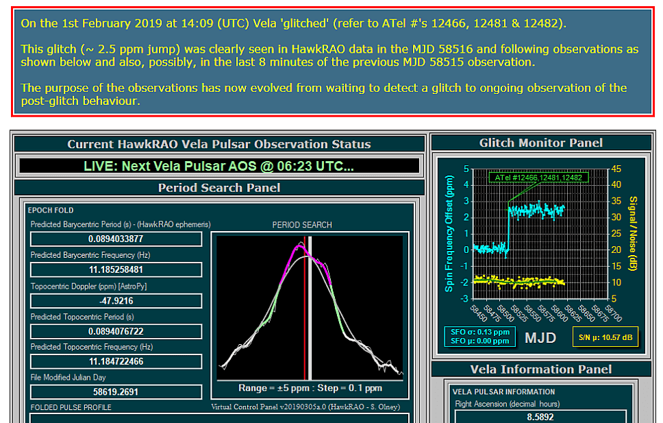
His observations indicate that Vela glitched and spun up by 2.5PPM at 14:09 UTC on Feb 1, 2019. He claims that this glitch detection is a first for amateur radio astronomy as far as he is aware.

If you're interested in Pulsar detection, check out a few of our previous posts on the topic.

The HawkRAO Amateur Radio Telescope Vela Glitch Detection
The HawkRAO Amateur Radio Telescope Vela Glitch Detection (Blue graph on the right indicates the glitch detection)

LimeSDR Angle of Arrival Experiments at 145 MHz

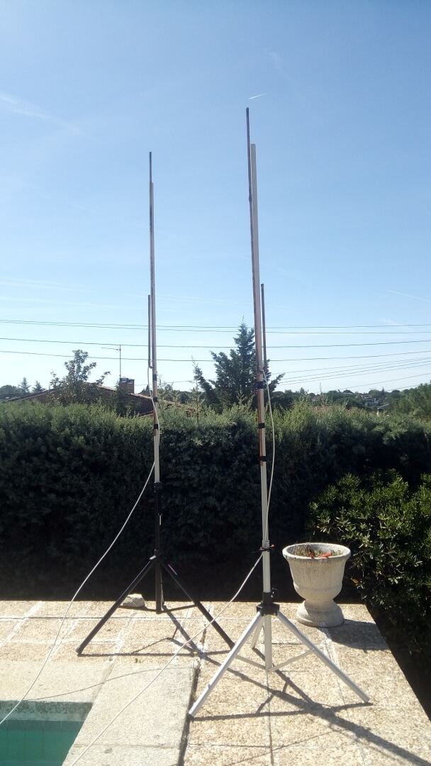
Two J-Poles used in LimeSDR Angle of Arrival Experiments.

Together with some Spanish amateur radio operators, Daniel Estevez performed an experiment with the goal of detecting the angle of arrival of meteor reflections coming from the GRAVES radar at 143.05 MHz.

The GRAVES radar at 143.05 MHz is often used by amateur radio astronomers as a way to detect the echos of meteors entering the atmosphere. The basic idea is that meteors leave behind a trail of ionized air which is reflective to RF energy. This RF reflective air can reflect the signal from the powerful GRAVES space radar in France, allowing the radar signal to be briefly received from far away. Detecting the angle of arrival from these reflections could help determine where the meteor entered the atmosphere.

Their experiments used a pair of J-Pole antennas and a LimeSDR receiver. The LimeSDR has two channels and can receive the signal coherently from both channels. The phase difference in the received signals from the two antennas can then be measured, and the angle of arrival calculated.

In their testing the first tested with 145 MHz amateur radio satellites. Unfortunately due to the low elevation of the antennas and multipath from terrain obstructions an angle could not be calculated. In a second experiment they tried receiving terrestrial APRS signals. With APRS they were successful and were able to determine the angle of arrival from multiple stations. Unfortunately for GRAVES meteor echoes they were not entirely successful, citing multipath issues due to houses, and the need for a clear view of the horizon.

We note that it may be possible to perform similar experiments with our KerberosSDR coherent RTL-SDR unit.

Using an RTL-SDR and OpenCV To Create an EMI Heatmap of Circuit Boards

Over on YouTube and his blog user Charles Grassin has uploaded a short video and blog post showing how he's using an RTL-SDR EMI (electromagnetic interference) probe and OpenCV to create a visual EMI heatmap.

Earlier this month we posted about Dmitris' experiments in which he was able to create a home made EMI/EMC probe out of a loop of semi-rigid coax and an RTL-SDR V3. This type of probe is useful for determining what components or areas on a circuit board are emitting electromagnetic interference. EMI testing for PCBs may be critical for passing compliance tests.

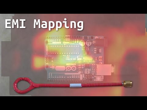
Charles' project takes the RTL-SDR EMI probe idea a step further by combining it with OpenCV. OpenCV is an open source library of code for computer vision applications. With the EMI data generated by the RTL-SDR EMI probe, and a camera pointed at a PCB, Charles is able to overlay a heatmap on top of the visual image which reveals the EMI hot spots on a PCB.

The video below shows the EMI heatmap of an Arduino PCB being mapped out. His blog post shows some other examples like a keyboard and a hairpin RF filter. The code he's created is open source and available on his EMI_Mapper GitHub page.

EMI mapping (OpenCV and RTL-SDR)

SignalsEverywhere: KerberosSDR Direction Finding Video Tutorial

Over on his YouTube channel SignalsEverywhere, Corrosive has uploaded a new video about setting up a KerberosSDR for direction finding. KerberosSDR is our new 4-input Coherent RTL-SDR that was crowdfunded on Indiegogo, and has now shipped to all backers. With KerberosSDR applications like direction finding and passive radar are possible. If you're interested, there are still about 70 units available in this batch. After that a second batch will be available in a few months.

In the video he goes over the full set up procedure, from setting up his chosen computing platform (a Raspberry Pi 3) to connecting up the KerberosSDR, connecting to it's web interface, calibrating, setting up the antennas, and then demonstrating some direction finding with four whip antennas on his car and a HackRF used as a signal source.

Radio Direction Finding Equipment KerberosSDR Coherent 4 x RTL SDR RDF Setup