Using a LimeSDR To Detect Aircraft Reflections from a 2.3 GHz Beacon

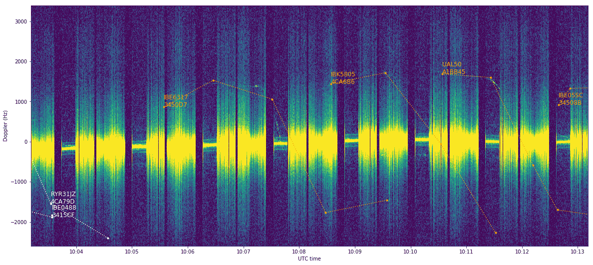
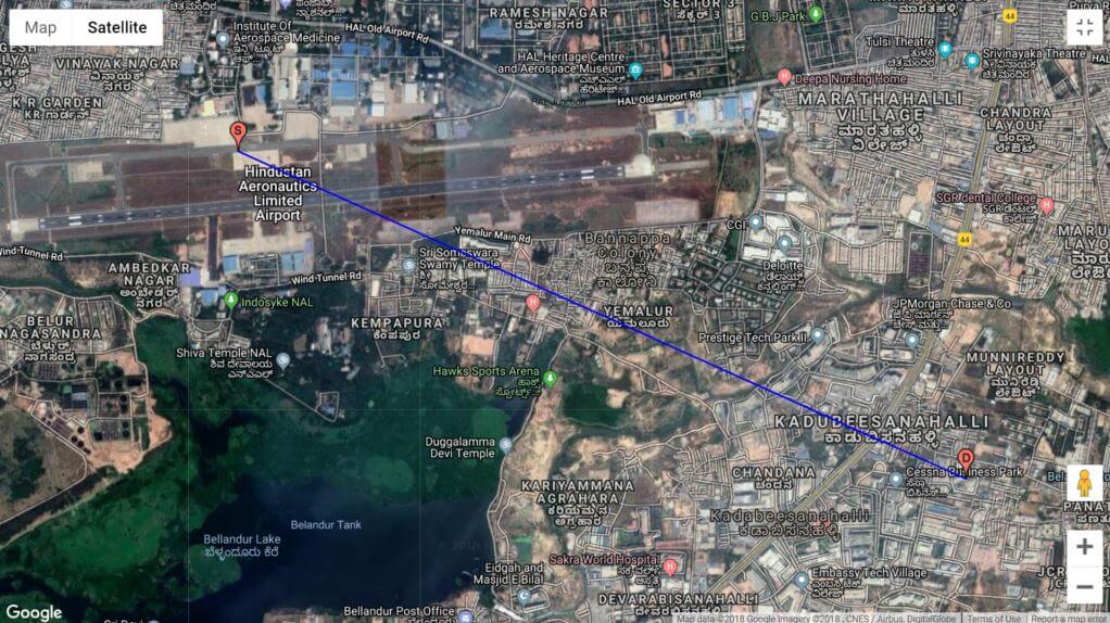
Over on his blog author Daniel Estevez has described how he's been listening to aircraft reflections from a 2.3 GHz 2W beacon. The beacon is 10km away from Daniels location and transmits a tone and CW identification at 2320.865 MHz. As aircraft fly nearby to his location Daniel was able to observe aircraft reflections of the beacon, and was able to match them with ADS-B position and velocity reports.

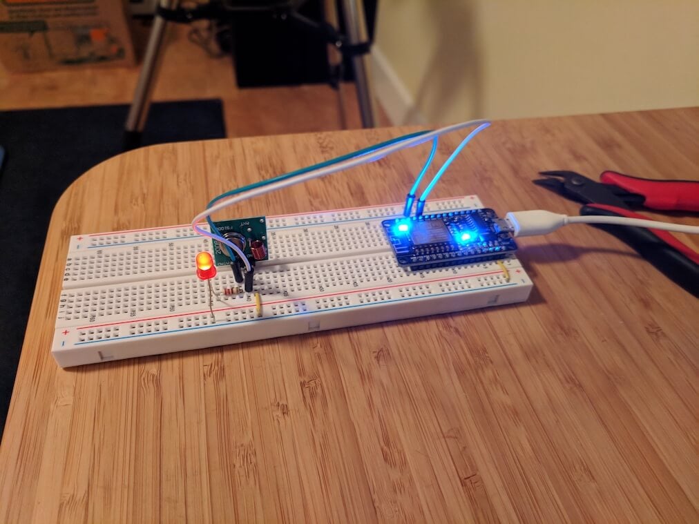
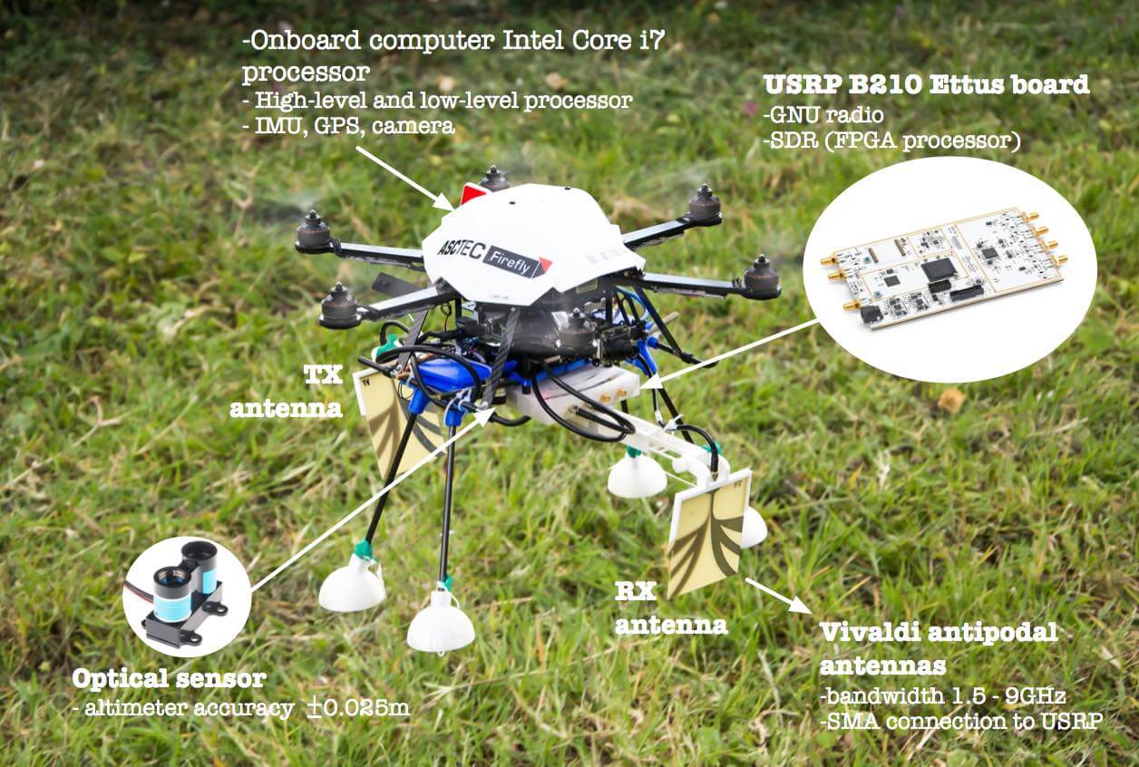
The hardware that he used was a LimeSDR and a 9dBi 2.4GHz planar WiFi antenna patch. By aiming the antenna away from the transmitter, and using his car as a shield to block the transmitter he was able to receive some reflections. Daniel recorded several reflections including one produced by a nearby car.

By combining his results with ADS-B data he was able to superimpose the results, and color aircraft tracks by either a negative or positive doppler shift which was observed from the reflection. By combining the ADS-B data with the time stamps, he was also able to mark the reflections from each aircraft.

Marking Aircraft Reflections at 2.3 GHz against ADS-B Data

YouTube Talk: Evaluating 9 of the Best Single Board Computers for Ham Radio SDR Systems

Over on YouTube the Ham Radio 2.0 channel has recently uploaded a talk that Scotty Cowling (WA2DFI) did at the 2018 TAPR digital communications conference. His talk centers around single board computers and his findings on the nine best single board computers (SBC) for ham radio SDR setups.

Scotty's talk begins by discussing why you'd want to use SBCs in your ham radio SDR setup, and explains why you might want to place them with the SDR close to the antenna, and then distribute the data over ethernet cable. He then reviews 9 boards listed below: 

  • Hardkernel Odroid C1
  • Raspberry Pi 3B
  • Hardkernel Odroid XU4
  • ASUS Tinker S
  • FriendlyElec NanoPC-T4
  • Pine64 RockPro64
  • 96 Boards Mediatek X20
  • 96 Boards HiKey 960
  • UDOO X86 Ultra

The boards are compared against CPU clock speeds, architecture, cache, debut year, RAM, boot ROM, bus speeds, OS support, and more. Scotty also discusses the need for low latency operation, but is yet to compare this on the boards. The best value for money boards that Scotty recommends end up being the Odroid XU4, Tinkerboard, NanoPC-T4 and the RockPro64.

Ham Radio 2.0: Episode 151 - Evaluating 9 of the Best Single Board Computers for Modern SDR Systems

Using an RTL-SDR to decode VOR Aircraft Navigation Beacons in Real Time

VOR stands for VHF Omnidirectional Range and is a way to help aircraft navigate by using fixed ground based beacons. The beacons are specially designed in such a way that the aircraft can use the beacon to determine a bearing towards the VOR transmitter. VOR beacons are found between 108 MHz and 117.95 MHz, and it's possible to view the raw signal in SDR#.

Over on RadioJitter author Arnav Mukhopadhyay has uploaded a post describing how to decode VOR into a bearing in real time using an RTL-SDR dongle. His post first explains how VOR works, and then goes on to show an experimental set up that he's created using a GNU Radio program.  With the software he was able to decode an accurate bearing towards the VOR transmitter at a nearby airport.

Arnavs post is a preview of an academic paper that he's worked on, and the full paper and code is available by request on the radiojitter post. We've also seen on YouTube that Arnav has uploaded a video showing the software working in action, and we have embedded it below.

Bearing to nearby airport VOR transmitter determined with an RTL-SDR and GNU Radio.

Reverse Engineering Wireless Blinds with an RTL-SDR and Controlling them with Amazon Alexa

Amazon Alexa is a smart speaker that can be programmed to control home automation devices via voice commands. For example, Stuart Hinson wanted to be able to control his wirelessly controlled blinds simply by verbally asking Alexa to close or open them. Stuart's blinds could already be controlled via a 433 MHz remote control, so he decided to replicate the control signals on an ESP8266 with 433 MHz transmitter, and interface that with Alexa. The ESP8266 is a cheap and small WiFi capable microchip which many people are using to create IoT devices.

Fortunately replicating the signal was quite easily as all he had to do was record the signal from the remote control with his RTL-SDR, and use the Universal Radio Hacker software to determine the binary bit string and modulation details. Once he had these details, he was able to program the ESP8266 to replicate the signal and transmit it via the 433 MHz transmitter. The remaining steps were all related to setting up an HTTP interface that Alexa could interface with.

If you're interested, we've also previously posted about another Alexa + RTL-SDR mashup which allows Alexa to read out ADS-B information about aircraft flying in your vicinity.

[First seen on Hackaday]

The ESP8266 with 433 MHz Transmitter

More KerberosSDR Passive Radar Demos

KerberosSDR is our upcoming low cost 4-tuner coherent RTL-SDR. With four antenna inputs it can be used as a standard array of four individual RTL-SDRs, or in coherent applications such as direction finding, passive radar and beam forming. More information can be found on the KerberosSDR main postPlease remember to sign up to our KerberosSDR mailing list on the main post or at the end of this post, as subscribers will receive a discount coupon valid for the first 100 pre-order sales. The list also helps us determine interest levels and how many units to produce.

In this post we're showing some more passive radar demos. The first video is a time lapse of aircraft coming in to land at a nearby airport. The setup consists of two DVB-T Yagi antennas, with KerberosSDR tuned to a DVB-T signal at 584 MHz. The reference antenna points towards a TV tower to the west, and the surveillance antenna points south. Two highlighted lines indicate roughly where reflections can be seen from within the beam width (not taking into account blockages from mountains, trees etc).

The second video shows a short time lapse of a circling helicopter captured by the passive radar. The helicopter did not show up on ADS-B. On the left are reflections from cars and in the middle you can see the helicopter's reflection moving around.

We are expecting to receive the final prototype of KerberosSDR within the next few weeks. If all is well we may begin taking pre-orders shortly after confirming the prototype.

Subscribe to our KerberosSDR Announcement

When preorders start subscribers to this list will receive a discount coupon valid for the first 100 pre-order sales. This list also helps us determine interest levels and how many units to produce, so please sign up if you're interested.

Please select all the ways you would like to hear from RTL-SDR Blog:

You can unsubscribe at any time by clicking the link in the footer of our emails. We use MailChimp as our marketing platform. By clicking below to subscribe, you acknowledge that your information will be transferred to MailChimp for processing. Learn more about MailChimp's privacy practices here.

Aerial Landmine Detection using USRP SDR Based Ground Penetrating Radar

Over the last few years researchers at Universidad Javeriana Bogotá, a University in Colombia, have been looking into using SDRs for aerial landmine detection. The research uses a USRP B210 software defined radio mounted on a quadcopter, together with two Vivaldi antennas (one for TX and one for RX). The system is then used as a ground penetrating radar (GPR).  GPR is a method that uses RF pulses in the range of 10 MHz to 2.6 GHz to create images of the subsurface. When a transmitted RF pulse hits a metallic object like a landmine, energy is reflected back resulting in a detection.

Recently they uploaded a demonstration video to their YouTube channel which we show below, and several photos of the work can be found on their Field Robotics website. We have also found their paper available here as part of a book chapter. The abstract reads:

This chapter presents an approach for explosive-landmine detection on-board an autonomous aerial drone. The chapter describes the design, implementation and integration of a ground penetrating radar (GPR) using a software defined radio (SDR) platform into the aerial drone. The chapter’s goal is first to tackle in detail the development of a custom designed lightweight GPR by approaching interplay between hardware and software radio on an SDR platform. The SDR-based GPR system results on a much lighter sensing device compared against the conventional GPR systems found in the literature and with the capability of re-configuration in real-time for different landmines and terrains, with the capability of detecting landmines under terrains with different dielectric characteristics.

Secondly, the chapter introduce the integration of the SDR-based GPR into an autonomous drone by describing the mechanical integration, communication system, the graphical user interface (GUI) together with the landmine detection and geo-mapping. This chapter approach completely the hardware and software implementation topics of the on-board GPR system given first a comprehensive background of the software-defined radar technology and second presenting the main features of the Tx and Rx modules. Additional details are presented related with the mechanical and functional integration of the GPR into the UAV system.

Drone with USRP Ground Penetrating Radar Setup
Aerial landmine detection using SDR-based Ground Penetrating Radar and computing vision

Constructing a 3D Printed Wideband 900 MHz to 11 GHz Antenna

Thanks to Professor John Jackson of JR Magnetics for writing in and sharing his design for a 3D printed wideband antenna designed for 50 Ohm 900 MHz to 11 GHz operation.

John required a wideband antenna that could cover the cellphone bands, WiFi, Bluetooth up to 6 GHz and the new USB band from 5 GHz to 10 GHz all in a single antenna installation. He also needed the impedance to be as flat as possible to reduce signal pulse distortion. First he looked into classic discone and sphere antenna designs, but found that while a sphere had the required bandwidth, it did not have the desired impedance characteristics, and a discone had the desired impedance characteristics, but not the ultra wide bandwidth required.

To get around this John combines the sphere and discone designs together to create a sort of icecream with cone looking shape. This results in the ultra wide bandwidth required, and a relatively flat SWR that stays below 2.

The design is easily reproducible by anyone with a metal 3D printer. The antenna's top hemisphere and cone are printed in brass, whilst the radome and supporting structure are printed in plastic.

We have uploaded John's original document here (pdf warning), and display some of the images below. The full build instructions can be found on his website, and John is also selling the 3D printed parts via Shapeways.

Spektrum SV Mod: RTL-SDR Spectrum Analyzer Software Now with Improved UI

Spektrum is a popular spectrum analyzer program that is used with RTL-SDR dongles. It is based on the command line rtl_power software and is compatible with both Windows and Linux. Thanks to it's easy to use GUI it is an excellent piece of software for scanning and determining where active signals exist, or for measuring filters and antenna SWR with a noise source.

Recently SV8ARJ (George) and SV1SGK (Nick) have been working on extending the original open source Spektrum code. Their improvements focus around the UI and making it more functional and easier to use. Currently the updated branch is in alpha, and they are hoping that any testers could help report bugs, issues and wishes to them. The code is available on their GitHub and the latest Windows test build can be downloaded from their DropBox.

The changelog reads:

  • 2 Cursors for Frequency axis.
  • 2 Cursors for Amplitude axis.
  • Absolute and differential measurements with cursors.
  • Zoom functionality of the cursors's defined area (gain + frequency).
  • Mouse Wheel Gain adjustment on graph (Top area for upper, low area for lower).
  • Mouse Wheel Frequency adjustment on graph (left area for lower frequency, right for upper).
  • Mouse Wheel in the centrer of the graph performs symetric zoom in/out.
  • View/settings store/recall (elementary "back" operation, nice for quick zoomed in graph inspection).
  • Right click positions primary cursors.
  • Right Double Click positions primary cursors and moves secondary out of the way.
  • Left Double Click zooms area defined by cursors (Amplitude + frequency).
  • Left Mouse Click and Drag on a cursor moves the cursor.
  • Middle (mouse wheel) Double Click resets full scale for Amplitude and Frequency.
  • Middle (mouse wheel) Click and Drag, moves the graph recalculating limits accordingly.
  • Reset buttons to Min/Max range next to Start and Stop frequency text boxes.
  • Cursor on/off checkbox now operate on all 4 cursors.
  • ZOOM and BACK buttons.
  • Filled-in graph option (line or area).
  • Display of frequency, Amplitude and differences for all cursors.
  • Modified: Button layout.
  • Fixed: Save/Reload settings on exit/start. IMPORTANT : delete the "data" folder from the installation location if you have it.
  • Filling in graph option (line or area).
Spektrum UI Updates
Spektrum UI Updates