KiwiSDR TDoA Direction Finding Now Freely Available for Public Use

A few weeks ago we posted about some experimental work going on with Time Difference of Arrival (TDoA) direction finding techniques on KiwiSDR units. The idea is that public KiwiSDRs distributed around the world can be used to pinpoint the physical locations of any 0 - 30 MHz transmitter using the TDoA technique. This feature has recently been activated and can be accessed for free via any KiwiSDR.

The KiwiSDR is a US$299 HF SDR that can monitor the entire 0 - 30 MHz band at once. It is designed to be web-based and shared, meaning that the KiwiSDR owner, or anyone that they've given access, can tune and listen to it via a web browser over the internet. Many public KiwiSDRs can be found and browsed from the list at sdr.hu or by signal strength and location on this website.

One thing that KiwiSDRs have is a GPS input which allows the KiwiSDR to run from an accurate clock, as well as providing positional data. Time Difference of Arrival (TDoA) is a direction finding technique that relies on measuring the difference in time that a signal is received at over multiple receivers spread out over some distance. In order to do this an accurate clock that is synchronized with each receiver is required. GPS provides this and is able to accurately sync KiwiSDR clocks worldwide. 

Just recently all KiwiSDRs were pushed with a beta update (changelog) that enables easy TDoA direction finding to be performed with them. Since many KiwiSDRs are public, this means that right now anyone can browse to a KiwiSDR web interface and start a direction finding computation. You don't even need to own a KiwiSDR to do this so this is the first freely accessible RF direction finding system available to the public. This could be useful for locating signals like numbers stations, military transmissions, pirate stations, jammers and unknown sources of noise.

KiwiSDR TDoA Interface
KiwiSDR TDoA Interface. Locating a STANAG Signal Source.

Usage

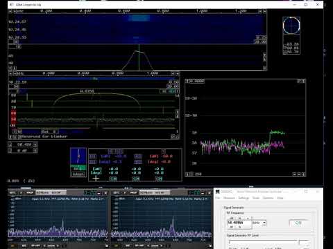
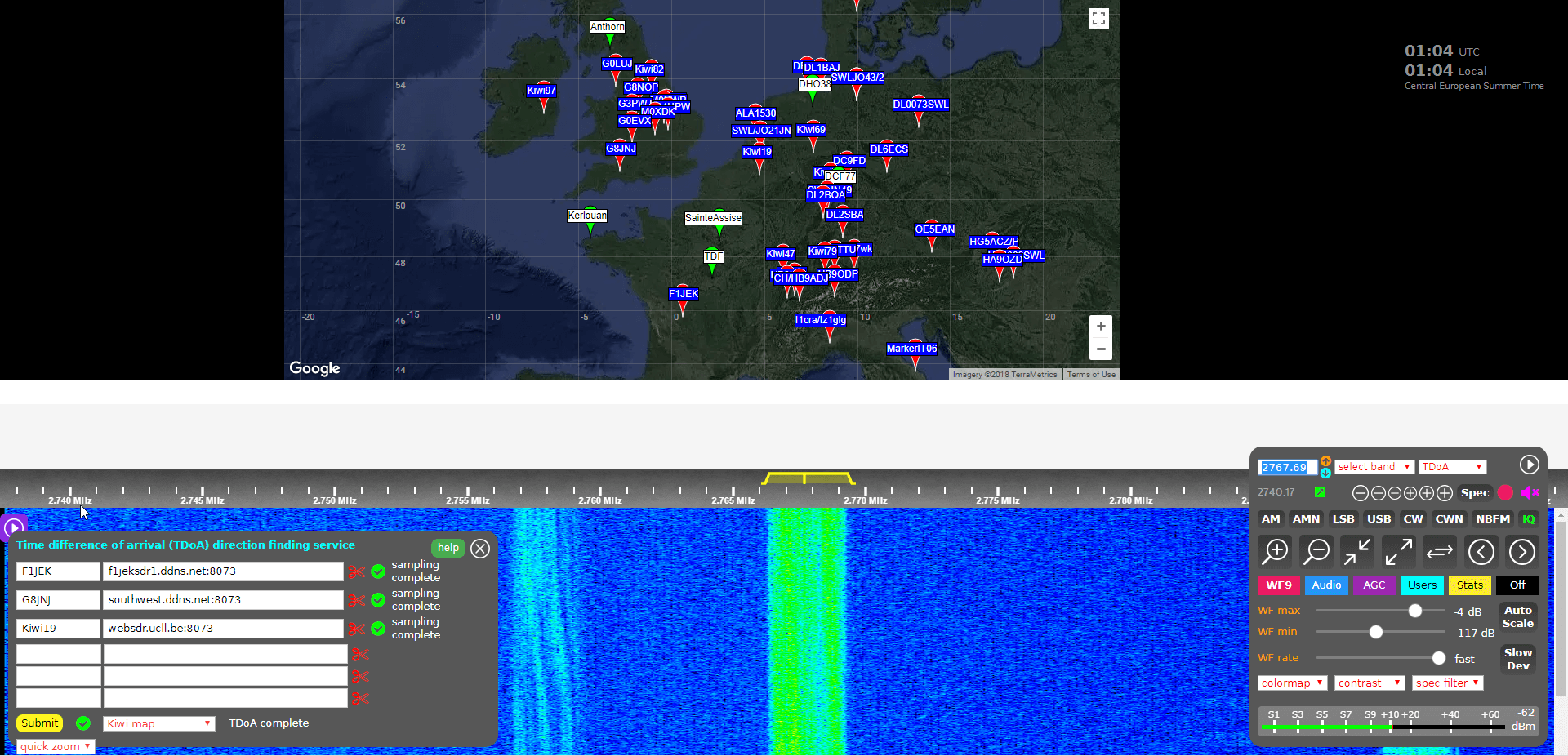
Running a TDoA job is as simple as using the KiwiSDR OpenWebRX GUI interface to select a signal and choose two or more receivers to use in the calculation.

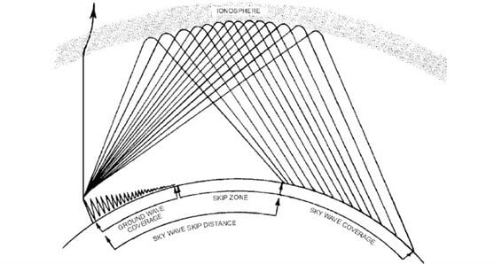
If you want to try this out then it's easiest to start with VLF/LF or MW stations (less than 1.6 MHz) as these signals tend to propagate to receivers only via direct ground wave. HF sky wave signals are a bit more difficult to locate as they tend to travel longer distances by skipping, bouncing and refracting around the ionosphere, so it is difficult to determine exactly where they are coming from since the bounces result in a difficult to predict time delay. But if you know the rough location of the transmitter, you can try and select nearby KiwiSDR receivers, which will hopefully ensure that the signals are received directly via ground wave, and not via sky wave. More advanced users could try using receivers spaced further away, but at similar distances from the expected transmitter location. This will hopefully ensure that all the receivers have identical skip distances, and thus identical delays.

Skywave and Groundwave Propagation
Sky wave and ground wave propagation. Ground wave is received directly vs sky wave which is received via ionospheric bounces

To get started follow these steps (and we also recommend reading the Help text, which is available by clicking the 'Help' button on the TDoA extension):

  1. Open a KiwiSDR that can receive some signals that you are interested in locating. You can browse KiwiSDRs by map and signal strength quality on this website.
      
  2. With the 'extension' drop down menu in the bottom right controls window choose TDoA and double check that the receiver modulation mode is set to 'IQ'.
     
  3. You should now see a map on the top half of the screen. This map displays all KiwiSDRs in the world that have GPS enabled and thus can be used for TDoA.

    The map also displays several known transmitters in white with green markers that can be used as TDoA practice. Clicking on a known transmitter will automatically tune the KiwiSDR to that station.
     
  4. Tune to the signal that you are interesting in locating. Make sure that the receiver bandwidth covers the signal.
     
  5. Now you need to find two or more KiwiSDRs on the map that can receive the signal that you're interested in locating. (Two will give you a line of possible locations, whilst three may allow you to pinpoint the signal. But we recommend starting with only two or three first as more receivers can cause the calculation to fail).
     
    To test and see if a KiwiSDRs from the map can receive the signal, double click on its marker. This will open the selected KiwiSDR in a new browser window, with it tuned to the station of interest. If you have a rough idea on where the transmitter is located, try to select KiwiSDRs such that they surround the transmitter.
     
  6. Once you've found a KiwiSDR that receives your signal of interest, close the second KiwiSDR receiver window that you just opened, and go back to the original KiwiSDR window. Now instead of double clicking just click once on the KiwiSDR pin on the map that you confirmed reception with. This will add that KiwiSDR to the window in the bottom left. This window displays the KiwiSDRs that will be used in the TDoA calculation.

    Make sure that it shows "XX GPS fixes/min" beside a selected KiwiSDR. If you get an error, remove that KiwiSDR and choose another.
     
  7. When you've found two or more KiwiSDRs that receive the signal of interest, position the map to where you'd like the TDoA result heat map to be displayed. The positioning of the KiwiSDR map will determine where the TDoA heat map plot is displayed.

  8. Click the 'submit' button to begin the TDoA calculations. The KiwiSDR server will gather 30 seconds of samples from each of your selected KiwiSDRs, and then run the TDoA algorithm on the KiwiSDR server. The whole process should take about 1-3 minutes to complete.
     
  9. Once completed you can view the results by using the drop down menu next to the submit button to choose the 'TDoA Map'
KiwiSDR TDoA Results
KiwiSDR TDoA Heat Map Results. Located a Military STANAG Signal Source in France.

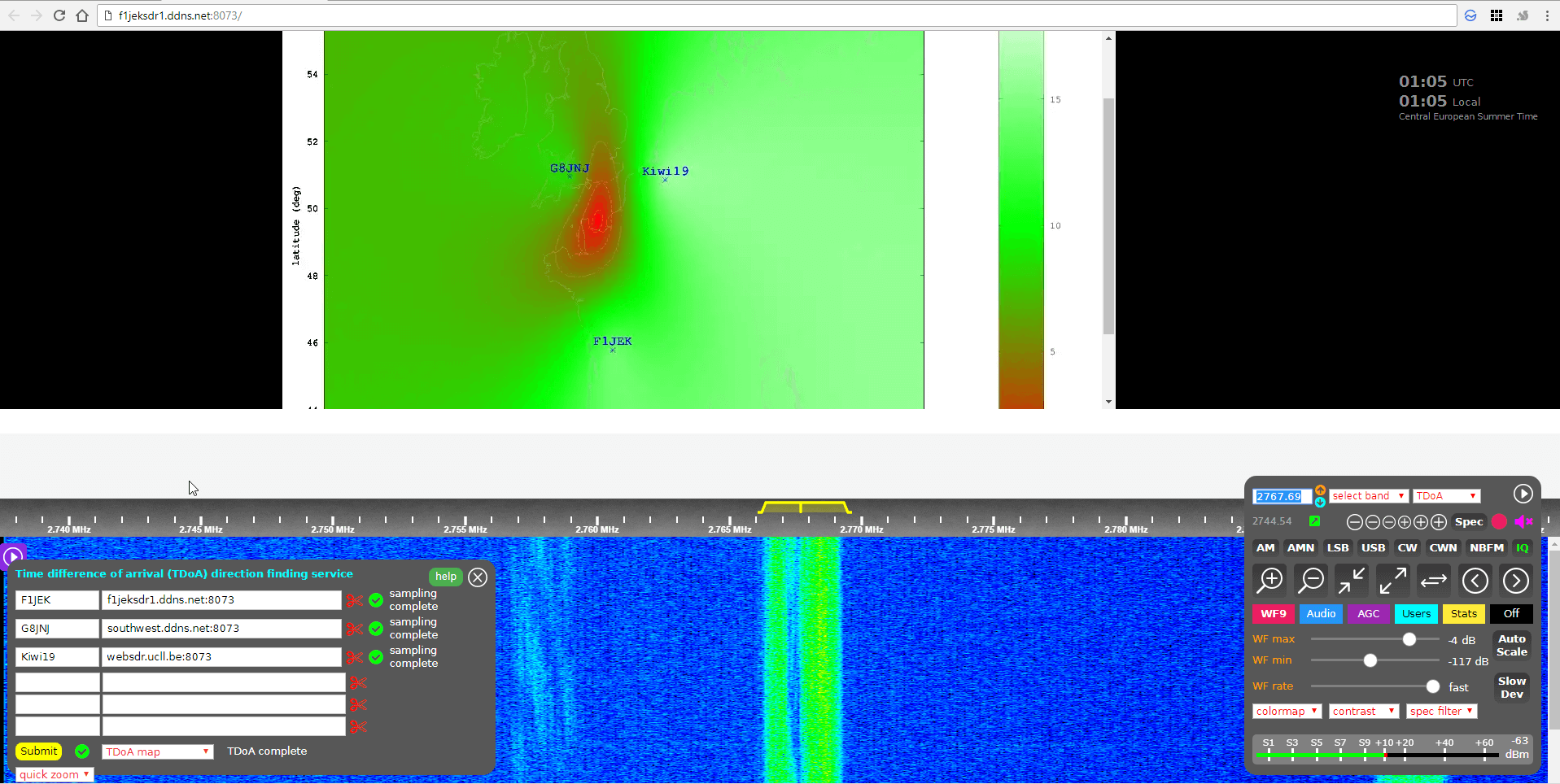
The KiwiSDR TDoA feature is still in testing and can be a little buggy. If you get "Octave Error", try refreshing the KiwiSDR page and trying again with different receivers. Sometimes you'll also get an error saying that the GPS of a KiwiSDR hasn't updated in a while. In this case just remove that receiver and choose another one. We also find that if you're zoomed too far out on the map, the TDoA algorithm will sometimes return 'Octave error'. Try zooming in a bit closer to the approximately expected location. KiwiSDRs can also only support four simultaneous users at a time, so during peak periods it's possible that some may become busy.

Over on the KiwiSDR forums Martin G8JNJ has also provided a list of helpful tips that he's discovered. For example he recommends choosing KiwiSDRs that are spaced evenly around the estimated transmitter location (if known). Ideally they should also be chosen an opposing pairs (e.g. one pair north and south of the transmitter, and one east and west of it).

Results

We tested the new TDoA feature a few times. Below are some examples of the results we achieved.

USA: NLK @ 24.6 kHz.

This is a Naval transmitter located in Seattle, Washington. With three receivers surrounding the transmitter, we were able to get a pretty close location marker, that is confirmed with the known location.

USA NLK
USA NLK

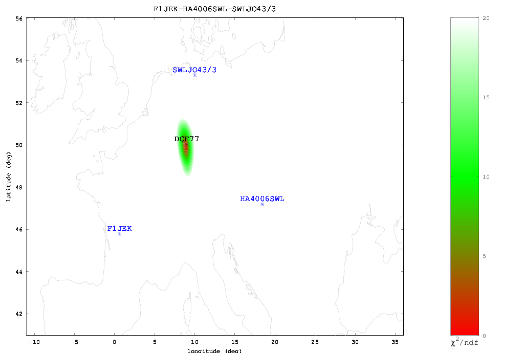
Europe: DCF77 Time Beacon @ 77.5 kHz.

This is a German long wave time beacon transmitter. Again with three receivers we were able to pinpoint the signal fairly accurately.

DCF77 Located with KiwiSDR TDoA

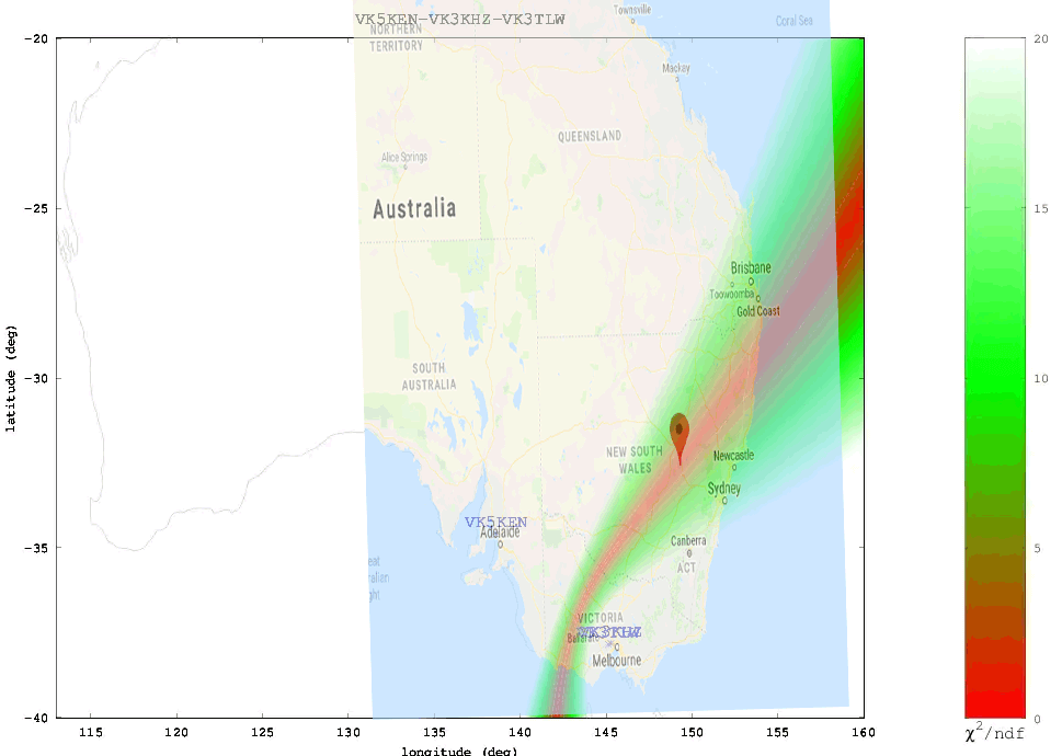
Australia: Local MW Radio Station @ 549 kHz.

Here we tried to locate an Australian MW station. Unfortunately in Australia there is a lack of KiwiSDRs, and of the ones that are there, only three had GPS enabled and could receive the MW station, and two of those were right next to each other. With only effectively two stations we could only obtain a line of possible locations. Comparing with the known location plotted on Google Maps we confirmed that the transmitter is indeed located on the line.

ABC Western Plains Australian MW Radio Station

We also tested a few signals at higher frequencies. As mentioned previously, anything above VLF/LF/MW (ie the HF bands) is a lot more difficult to locate since the signal can bounce around the atmosphere and can case extra delays to occur in the signal arrival time. The extra delays can cause problems with the time of arrival measurements. Thus for these signals it's important to find receivers close to the transmitter, or receivers spaced further away at the same distance so they each have identical skip distances, and thus identical delays.

When locating an HF signal that is in a completely unknown location we recommend starting with only two or three receivers, checking the heat map, and slowly adding more receivers in the hot parts of the heat map and removing receivers that turn out to be in the cooler areas. This way you can slowly narrow down the receivers to ones that are closer to the signal source, and are thus more likely to receive the signal directly, rather than via ionosphere bounces.
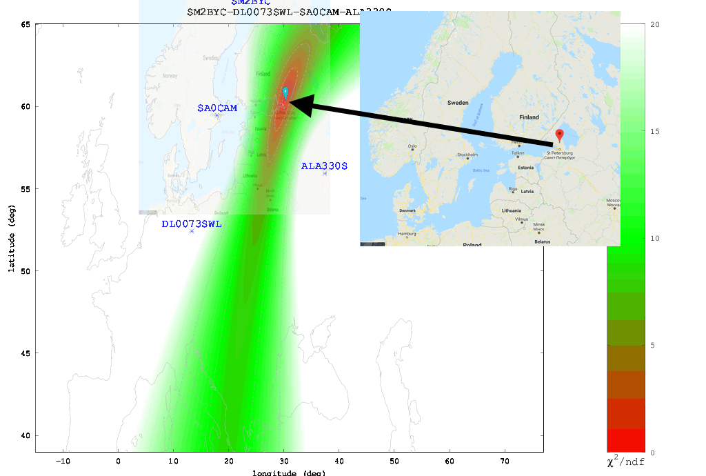
The Buzzer (UVB-76)

Using the just previously mentioned technique we attempted to locate the source of the Buzzer (UVB-76), a Russian numbers station at 4.625 MHz. Eventually we came to the results shown below. According to the heat map the buzzer appears to be located somewhere in the vicinity of St. Petersburg. Back in 2014 the numbers station researchers at priyom.org received an anonymous tip from a member citing a transmitter location just north of St. Petersburg. The TDoA heat map results seem to confirm that the anonymous tipper is correct.

The Buzzer (UVB-76)
The Buzzer (UVB-76) TDoA Heatmap compared against the known location

Final Words

Right now the biggest problem appears to be the lack of active KiwiSDRs around the world. The more active KiwiSDRs there are, the better the direction finding results can be. At the moment Northern Europe and the USA are fairly well represented, but the rest of the world is not. Asia, Africa, Russia and South America are especially lacking. Also not all KiwiSDRs are utilizing the GPS feature. If you are running a KiwiSDR please do consider activating the GPS option. Another issue is that many KiwiSDRs suffer from poor reception and bad antenna setups, so not all active receivers are actually useful.

In the future we expect this feature to only improve, with the people behind it, John Seamons and Christoph Mayer, working hard to improve results. For example one possible future improvement is utilizing ray-tracing techniques to try and take into account delays caused by sky-bounce propagation. Update (15 July 2018): You can now also plot results over Google Maps.

If you want to purchase a KiwiSDR and contribute to the worlds first freely accessible TDoA system, you can purchase it immediately on Amazon or Seeed Studios for $299, or wait for a sale to occur on massdrop.com, where it is often discounted by up to US$100.

Exposing Hospital Pager Privacy Breaches

It has been a known open secret that for years many hospitals have been transmitting sensitive patient data over the air completely unencrypted via their pager network. With a simple ultra cheap radio such as an RTL-SDR, or any other cheap radio scanner such as a Baofeng, it is possible to eavesdrop on this sensitive data with very little technical knowledge required. Hospitals appear to be reluctant to upgrade their systems despite clearly being in violation of HIPAA privacy regulations in the USA.

Recently, @WatcherData has been trying to bring attention to this ongoing security breach in his home state of Kansas, and last month was able to get a news article about the problem published in the Kansas City Star newspaper. Over on Twitter he's also been actively documenting breaches that he's found by using an RTL-SDR to receive the pager messages.

Interestingly, publicity generated by @WatcherData's newspaper article has brought forward a hostile response from the hospital in question. Over on Reddit /r/legaladvice, a forum where anyone can ask legal advice questions, @watcherdata posted the following:

I discovered some time ago that hospitals throughout my region of the US are sending messages to physician pagers that include the name, age, sex, diagnosis, room number, and attending physician. These can be seen by anyone with a simple RTL SDR device, and a couple of free programs.

This seems like a massive HIPAA violation. So I contacted the main hospital sending out most of the information, and they were extremely grateful. I got a call within a day from a high level chairman, he explained their steps to remediate, that their auditors and penetration testers missed it, and that they would have it fixed within a week. Sure enough, they started using a patient number and no identifiable information in the pages. A couple of other hospitals have fixed their systems too, after I started contacting them via Twitter.

Early on in this process, I contacted my local newspaper. They reached out to the hospital in question, and were met with a "very hostile" response. They immediately deflected from any HIPAA violations and explained that I (the source) am in violation of the Electronic Communications Privacy Act of 1986.

This was enough to scare me off completely. I've nuked all log files from my systems and stopped collecting data. The reporters want to know how I would like to proceed. Originally, I was going to get full credit for the find in their article. But now, I at least need to be anonymous, and am thinking about asking them not to run the story at all.

Among the replies there doesn't seem to be consensus on whether simply receiving pager messages in the USA is legal or not.

In the past we've seen similar attempts to bring attention to these privacy breaches, such as an art installation in New York called Holypager, which simply continuously printed out all pager messages that were received with a HackRF for gallery patrons to read.

HolyPager Art Installation. HackRF One, Antenna and Raspberry Pi seen under the shelf.
HolyPager Art Installation. Printing pager messages continuously.

New GNU Radio Block for Decoding Meteor M2 Images

Thank you to Reiichiro Nakano for submitting news about his work on converting the Pascal based meteor_decoder software into a C++ GNU Radio block. meteor_decoder is a decoder for the Meteor M2 weather image satellite. Meteor M2 is a Russian weather satellite that transmits images down in the digital LRPT format. This provides much higher resolution images compared to the NOAA APT signals. With an RTL-SDR, appropriate satellite antenna and decoding software it is possible to receive these images.

Reiichiro works for Infostellar, which appears to be a Japanese company aiming to connect satellites to the internet via distributed and shared ground stations. It appears to be somewhat similar to the SatNOGs project. Reiichiro writes:

Just wanted to share a simple project I built for my company Infostellar, in the past week. I converted https://github.com/artlav/meteor_decoder to C++ and placed it within a GNURadio block for direct decoding of Meteor M2 images. It's a sink that expects soft QPSK demodulated signed bytes. Once the flowgraph stops running, it parses out received packets and dumps the received Meteor images in a specified location. 

The block is part of our Starcoder repository and can be installed from here (https://github.com/infostellarinc/starcoder/blob/master/gr-starcoder/lib/meteor_decoder_sink_impl.cc ).

Noise Cancellation using Linrad and the Phase Coherent Capabilities of an RSPduo

The RSPduo is the latest product from SDRplay, and it's main defining feature is it's dual RX channels. The two channels allow you to simultaneously listen to two stations that may be at opposite ends of the spectrum. Of course the same could be done cheaper with two separate RSP1A devices, however the advantage of the RSPduo is that the two channels are phase coherent. This opens up a lot of technical possibilities such as active noise cancelling/spatial filtering of an interfering signal or unwanted RF noise.

The basic idea behind phase coherent noise cancelling is that you have one antenna pointed towards your signal of interest, and the other pointing towards the interfering signal or coupled to the unwanted noise source. The unwanted signal/noise can then be subtracted from the signal of interest, resulting in a cleaner signal. This can only be done if the two channels are phase coherent like they are on the RSPduo.

Over on YouTube and his blog, ICAS Enterprises has been experimenting with noise cancelling on his RSPduo [Part 1] [Part 2]. The blog is entirely in Japanese, but all the relevant screenshots are in English, and we have provided Google Translated links. SDRplay have also provided a description of the process on their blog. The idea is to use Linrad to process the sound output of the two RSPduo channels from SDRuno. Linrad has capabilities that allow you to subtract two signals from one another.

In his experiments he receives a known 50 MHz CW beacon, and then injects an interfering test signal into the system. Then using Linrads 'signal adaption' feature he is able to completely remove the interference. 

RSPduoでのノイズキャンセルの実験 - Linrad使用

Video on Hacking 433 MHz Devices with an RTL-SDR and Raspberry Pi

Over on YouTube user Andreas Spiess has uploaded a video showing how to use an RTL-SDR to reverse engineer 433 MHz ISM band devices such as Internet of Things (IoT)/home automation sensors and actuators. 

Andreas decided to do this because he has a 433 MHz remote controlled actuated outdoor awning which he wants to have automatically retract when the wind speed gets too high. To do this he wanted to use a wireless 433 MHz ISM band weather station with wind speed sensor. But unfortunately he discovered that it has a proprietary protocol that can't talk to his awning, which also has it's own proprietary protocol.

Andreas' solution is to use an RTL-SDR and Raspberry Pi running the rtl_433 decoder software to receive the weather station data. The rtl_433 software already contained a decoder for his weather station, so no further reverse engineering was required. The data is then converted into MQTT which is a common TCP/IP protocol for IoT devices. MQTT is then read by Node-RED which is a flowgraph based programming environment for IoT devices.

Next, unlike the weather station rtl_433 did not already have a decoder implemented for his awning. So Andreas had to reverse engineer the signal from scratch using the Universal Radio Hacker software. Using the reverse engineered signal information, Andreas then uses an ESP32 processor/WiFi chip and cheap 433 MHz transmitter to implement a clone of the awning's remote control signals. The ESP32 is programmed to understand the MQTT data sent from the Raspberry Pi via WiFi, so now the weather station can control the awning with a little bit of logic code in Node-RED.

#209 How to Hack your 433 MHz Devices with a Raspberry and a RTL-SDR Dongle (Weather Station)

The Outernet Ku-Band LoRa Data Service

As mentioned in our previous post about the Outernet LoRa chat application, Outernet is currently holding a 33% off sale on their 'Dreamcatcher' satellite data receiver. To get the discount use the coupon "33%OFFJULY4SALE" on their store. The sale lasts until Midnight Central Time on Wednesday 4 July. The code is valid site wide, so applies to the moRFeus product as well.

In this post we'll highlight the Outernet data service which can be received in the Continental USA with the Dreamcatcher 3 hardware.

Outernet is a free download only satellite based information service that aims to be a sort of 'library in the sky'. Their aim to to have satellites constantly broadcasting down weather, news, books, radio, web pages, and files to everyone in the world. As it's satellite based, the service is censorship resistant, and useful for remote/marine areas without or with slow/capped internet access.

Currently the Outernet data service is considered to be beta, and is only available for those in the Continental United States.

The New Outernet Data Service

Originally a few years ago Outernet started with a 12 GHz DVB-S satellite service that gave 1GB of content a day, but that service required a large dish antenna which severely hampered user adoption. Their second attempt was with an L-band service that only needed a small patch antenna. This service used RTL-SDR dongles as the receiver, so it was very cheap to set up. Unfortunately the L-band service had a very slow data rates (less than 20MB of content a day), and leasing an L-band transmitter on a satellite proved to be far too expensive for Outernet to continue with. Both these services have now been discontinued.

Outernet 3.0 aims to fix their previous issues by giving us a service that provides over 300MB of data a day, with a relatively cheap receiver, computer and antenna combination that is small and easy to set up. The new receiver uses a standard Ku-Band LNB as the antenna, which is very cheaply available as they are often used for satellite TV reception. The receiver is called 'Dreamcatcher 3', and is a custom PCB containing a hardware receiver (non-SDR based) with a LoRa decoder, as well as an embedded ARM computer capable of running Linux.

LoRa is an RF protocol that is most often associated with small Internet of Things (IoT) devices, but Outernet have chosen it as their satellite protocol for Outernet 3.0 because it is very tolerant to interference. In Outernet 3.0 the LNB is pointed directly at the satellite without any directive satellite dish, meaning that interference from other satellites can be a problem. But LoRa solves that problem by being tolerant to interference.

The Data Service

Currently, Dreamcatcher 3 users are receiving data such as hundreds of daily news articles, global weather information and the top 100 most searched Wikipedia articles of the day. A new satellite radio broadcast service is also being tested (kind of similar to Sirius XM, but only one channel at the moment). Compared to the older L-band Outernet service, the larger data rates allow for a lot more data and thus articles to come down.

Like previous iterations, the Dreamcatcher 3 board runs remotely on a WiFi connection. You then connect to the Dreamcatcher 'Skylark' web interface via a PC or mobile browser. On this web interface you can browse all your downloaded files. The user guide is a good read for understanding the set up procedure. 

Some screenshots of example received data are shown below.

Conclusion

Outernet have been working hard to perfect their service over the years, and the current offering is the best compromise between ease of use and data rates that we've seen so far. Unfortunately the service is only available in the Continental USA at the moment, but we're looking forward to future expansion. 

Currently we'd only recommend purchasing the Dreamcatcher 3 receiver for the Outernet data service if you understand that the service is in beta, requires a little bit of technical know-how, and like previous Outernet iterations is subject to possible change. Support is only available via their forums.

We can see the service being popular with those who live and work in remote areas without or with expensive internet. Censorship resistance is also another big plus, but satellites would need to be rented for these areas first.

There are also more creative uses. 'Unplugged' getaways are becoming popular in the modern world. Perhaps you want an internet free holiday, but don't want to miss out on important breaking news and weather updates for safety. In the future Outernet could also be used for Bitcoin or other Cryptocurrency blockchain transmission. In past Outernet iterations it was also possible to send a tweet that would be re-transmitted by Outernet. A similar messaging service could be used to control remote devices.

New RTL-SDR Frequency Heatmap Generator Plugin for SDR#

Thanks to VE3NEA for letting us know about his new RTL-SDR compatible heatmap generator plugin for SDR#. To use the plugin you first need to generate some heatmap CSV data by using the rtl_power software. You can then open the CSV file in the plugin and it will generate a heatmap image. A frequency heatmap shows a wideband waterfall image of detected frequency activity.

RTL-SDR heatmap tools are nothing new, but the convenience of having it as a SDR# plugin is that you can click on the heatmap image to instantly tune to a frequency where activity was recorded during the initial rtl_power scan.

SDRSharp RTL-SDR Heatmap Plugin

Outernet Dreamcatcher 3 Sale $99 for the Full Kit + Testing the LoRA Chat Application

The Dreamcatcher v3.0 is Outernet's latest revision of their satellite receiver hardware. The freely available Outernet ku-band satellite service aims to keep us up to date with the latest news, provide books, videos, a daily selection of Wikipedia articles and satellite radio. Compared to the internet, Outernet is download only, and is received via their Dreamcatcher 3 hardware with an an antenna pointed to a satellite. At the moment their Ku-band service is in beta testing and so is only available in the continental United States, but they hope to eventually expand to cover more areas of the world.

Starting from today Outernet are holding a 33% off sale. This means that their Dreamcatcher 3 is only US$99 each. To get the discount use the coupon "33%OFFJULY4SALE" on their store. The sale lasts until Midnight Central Time on Wednesday 4 July. The code is valid site wide, so applies to the moRFeus product as well.

Previous Dreamcatcher implementations utilized an RTL-SDR to receive their L-Band network, however that network has now been discontinued. Dreamcatcher 3 utilizes a hardware based LoRa radio to receive their new ku-band satellite LoRa data stream. However, Dreamcatcher 3 has alternative applications, and doesn't need to be used only for the Outernet data service. Dreamcatcher 3.0 is a full LoRa radio that can transmit and receive, and in this post we'll focus on testing that out.

LoRa is a popular wireless protocol that has been designed for Internet of Things (IoT) devices. It is robust against interference and can be used in low power devices.

Dreamcatcher 3 LoRa Chat

Outernet have provided a LoRa two way open source text chat application that runs on the Dreamcatcher 3. To use it you'll need two Dreamcatcher 3 boards. With the application you'll be able to chat with short text messages in real time between the boards. Amateur radio enthusiasts may be interested in the boards as an easy way to set up LoRa experiments.

We note that Outernet are not advertising the transmit features specifically as the board is not FCC approved as an intentional radiator, so it cannot legally be used as an ISM band LoRa device for transmitting and listening to LoRa IoT sensors. But as a ham you are able to transmit with it if you can ensure that the output is clean and legal and on the ham bands. 

Dreamcatcher 3.0 Running LoRa Chat App
Dreamcatcher 3.0 Running the LoRa Chat App

A brief demo of the chat running below is shown. In the video we're using the default 'spreading factor' setting which results in robust communications, but results in a latency of about 2 seconds. Later we'll show how to change the spreading factor to reduce latency.


The Dreamcatcher v3.0

Outernet kindly provided us with two Dreamcatcher 3 boards to test the chat application with.

Like the previous versions, the Dreamcatcher is a full computing board with radio built into it. Except this time instead of an RTL-SDR, the radio is a hardware LoRa module. Another difference is that now there is a built in LCD screen.

On the board there are two SMA ports, one labelled "Direct" and the other labelled "LNB". The direct port is what we'll need to use for the chat application as this is the port that can transmit. There are also two SD Card slots, one for the OS and one for storage, a microphone and headphone jack, a USB-A slot with a supplied WiFi adapter, and two USB micro slots, one for USB OTG and one for power.

The package also comes with an LNB that is designed to be used with the Outernet satellite service. The LNB is receive only, so cannot be used with the chat application, so you'll need to use your own antenna if experimenting with the LoRa transmitter.

Chat Setup and Usage

First we burnt the latest version of Dreamcatcher Armbian OS to two SD cards and inserted one into each board. Since Dreamcatcher 3 has a built in LCD screen, you can login and access the terminal through the screen. But as there is only one USB port available, you'll need a USB hub to be able to plug in a mouse and keyboard, and the included USB WiFi adapter. Alternatively, if you connect the USB OTG port to a PC, you can connect to it via a USB serial connection. Instructions for connecting via serial, and for setting up a WiFi connection are the same as in our previous Dreamcatcher 2.0 tutorial.

The chat software is available on GitHub at https://github.com/Outernet-Project/Dreamcatcher-Packet-Tester. To install it simply run the following commands at the Dreamcatcher's terminal:

sudo apt update
sudo apt install libsoc-dev libsoc2
git clone https://github.com/Outernet-Project/Dreamcatcher-Packet-Tester
make

Then you can run the chat program with:

sudo ./chat

Upon running the program you'll be asked to enter a MIXER frequency. This frequency doesn't really seem to matter and we're not sure why we're asked for it. But you can enter any frequency such as 300000000 Hz (300 MHz).

Once you've opened the chat program on both Dreamcatchers you should be able to type in text on the console, and have it show up on the other Dreamcatcher after pressing enter. Remember to plug an antenna in to the DIRECT port of both Dreamcatchers, or run of attenuated coax between them. The provided LNB cannot be used for the chat application.

Playing with LoRa Settings

The actual RF output frequency is by default hard coded in at 2.4 GHz. If you want to change it you can edit the main.cpp file with a terminal based text editor like nano, and look for the #define RF_FREQUENCY entry. Then you will need to recompile by running 'make' again. However note that at the time of this post, according to Outernet the software only works properly at around 2.4 GHz. Apparently this is simply a software limitation and once this is fixed you should be able to transmit at any frequency between 85 MHz to 5400 MHz.

Also by default, the LoRa 'Spreading Factor' is set to the maximum of 12. This means that there is roughly a latency of about 1 second between sending a message, and receiving it on the other unit.

The spreading factor can also be adjusted in the code by editing the "modulationParams.Params.LoRa.SpreadingFactor" variable. This determines how spread out in time the packet it. Larger spreading factors result in more robust error free communications, whereas smaller factors result in lower latency.  Below are some valid spreading factor entries for the code.

Note that if you reduce the spreading factor you'll also want to reduce the RX_TIMEOUT_VALUE and TX_TIMEOUT_VALUE #defines (you'll need to search for these lines in the code. Hint: In Nano CTRL+W is search.). For a spreading factor of 7 a timeout of 100 ms works well.

LORA_SF5 
LORA_SF6 
LORA_SF7 
LORA_SF8 
LORA_SF9 
LORA_SF10 
LORA_SF11 
LORA_SF12

It is also possible to adjust the bandwidth from 200 kHz up to 1600 kHz using the following code on the "modulationParams.Params.LoRa.Bandwidth" variable.

LORA_BW_0200 
LORA_BW_0400 
LORA_BW_0800 
LORA_BW_1600

The LoRa 'coding rate' can also be changed via the "modulationParams.Params.LoRa.CodingRate" variable.

LORA_CR_4_5 
LORA_CR_4_6 
LORA_CR_4_7 
LORA_CR_4_8 
LORA_CR_LI_4_5 
LORA_CR_LI_4_6 
LORA_CR_LI_4_7

You can also adjust the TX output power by adjusting the value specified by #define TX_OUTPUT_POWER. By default it is set to the maximum output power of 13 dBm. The lowest value available is -18 dBm. 

Remember that after making a change in the main.cpp file, you'll have to recompile the chat program by running 'make'.

Below we visualized the different LoRa spreading factors with a HackRF. It's interesting to see how the spreading factor changes the packet transmit time.

Comparing LoRA Spreading Factors
Comparing LoRa Spreading Factors

Conclusion

Overall the Dreamcatcher 3 LoRa chat software works, but is still very much in early development. Regardless it is an interesting tool for experimenting with LoRa. The hardware is ready, and software now just needs to be developed to make use of the LoRa protocol. We also note that the Dreamcatcher is not a plug and play device, and that it's mostly suited to people who enjoy tinkering with new beta products.

We'd also just like to remind that in order to legally transmit you'll need a ham licence. The board is not FCC approved for regular ISM band LoRa use. While the output power of the Dreamcatcher isn't too strong at a maximum of 13 dBm, we still recommend that you make sure to reduce the output TX power, or run a direct attenuated coax connection when testing. There are also weak signal images present at some harmonics, so any ham using this with an amplifier would be of course expected to provide sufficient filtering.