moRFeus is a low cost wideband signal generator and frequency mixer. It can be used to generate a tone anywhere from 85 MHz to 5400 MHz, and can also be used as a frequency mixer, allowing you to implement upconverters and downconverters. In past posts we've reviewed and seen it being used as a PC based signal generator with open source GUI's, downconverter, CW generator, and most recently as a tracking generator for measuring filters and antenna VSWR.
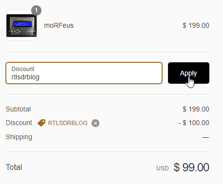
Currently Outernet are having a half price sale on the moRFeus. Normally it's US $199, but now with the coupon code "rtlsdrblog" it's only US $99. The sale only lasts until Saturday 09 June 2018, so get in fast if you want one.
As Outernet is currently having a sale and selling their their moRFeus product at only US $99 (see next post for details - or simply use coupon code "rtlsdrblog" on their checkout - valid until Saturday 09 May 18), we thought that we'd show an interesting use for the moRFeus when combined with an RTL-SDR.
Outernet's moRFeus is a signal generator and frequency mixer that can be controlled either by it's built in LCD screen, or via software on a Windows or Linux PC. It can generate a clean low phase noise tone anywhere between 85 to 5400 MHz. Because it can be computer controlled it is possible to use moRFeus as a tracking generator for characterizing filters and measuring antenna SWR. A tracking generator is just a signal generator that can be set to output at the same frequency that the measurement receiver is tuned to.
In the past we've posted a tutorial showing how to use a wideband noise source for measuring filters and antenna SWR. However, if available, a tracking generator is usually preferred over a noise source. A wideband noise source outputs high power at all frequencies, and so can easily overload an RTL-SDR causing reduced dynamic range and accuracy in measurements. This is especially the case when measuring bandstop filters as they pass all frequencies, apart from a small blocking band. Since so much noise gets through to the dongle, dynamic range is reduced.
This post shows how to use the moRFeus as a tracking generator together with an RTL-SDR for making RF measurements. This could be called a scalar network analyzer. The set up uses GQRX and a Python script, but in the future it is possible that someone may develop a standalone app.
Since the output of the moRFeus is quite strong, an attenuator is required to keep signal levels low enough to not overload the RTL-SDR.
The cheapest RF bridge we've found is available on eBay for about $7. With an RF Bridge you'll need a 50 Ohm dummy load as well to connect to the 'REF' port. Directional couplers seem to work more accurately however, and second hand minicircuits ones can often be found on eBay. A $2 TV 'tap' is also a directional coupler, and may also work, although we have not tested this.
Software Setup
In this tutorial we're using the method first described by 'LamaBleu' in his post to the Outernet forums. The method uses Linux and involves reading power levels from the RTL-SDR by using GQRX and it's remote telnet connection capabilities. The telnet command "F freq" can be used to change frequency in GQRX, and the command "l" can be used to read out the current power level in dbFS.
To control moRFeus we use Outernet's official "morfeus_tool", which is a command line based tool.
A basic Python script was written to set the frequency in moRFeus and GQRX at the same time. After a 500 ms settling time the power level is measured and recorded in a CSV file, then the script iterates to the next frequency. We iterate at 1 MHz intervals.
If you have a moRFeus and want to try this project out, copy and paste the script from pastebin, and name the file morfeus_scalar.py. Place the morfeus_scalar.py file and the morfeus_tool_linux_x32 tool into the home folder.
To get the software started:
Open GQRX and connect the dongle and required RF components for the test (shown below).
Set the RTL-SDR gain to zero or just low enough so that the signal doesn't cause overload (moRFeus signal levels are fairly high).
In the GQRX GUI ensure that the "Remote control via TCP" button is pressed in. (Looks like two computer screens).
Edit the Python script and choose the frequency range that you'd like to scan by setting variable FREQ_MIN and FREQ_MAX.
In a terminal run "sudo python morfeus_scalar.py".
When the script completes you'll have a file "out.txt" which is a CSV file of frequency and signal power levels.
Characterizing Filters
To characterize a filter (find the response of a filter) simply connect the system like so:
moRFeus Filter Test
But first connect just the moRFeus, attenuator and RTL-SDR together.
In GQRX increase the gain until just a few dB before the RTL-SDR overloads and starts showing signal images. This will maximize the available dynamic range.
Run an initial calibration scan with morfeus_scalar.py. Save the results in out.txt into a spreadsheet.
Connect the filter in the RF chain, and then run a second scan with morfeus_scalar.py. Save the results into another column in the spreadsheet.
Subtract the calibration scan results from the filtered results. Plot the resulting values using the spreadsheet software. This will show the response of the filter.
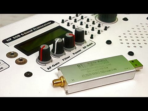
Over on YouTube OM0ET has shown how he uses his RTL-SDR for measuring crystals. While working on his home made HF 6-band SSB transceiver, OM0ET needed a way to measure the frequency of some 8 MHz crystals that he needed for his IF filter.
To perform the measurement he simply inserts the crystal into a homemade oscillator circuit, and measures the output with an RTL-SDR V3 operating in direct sampling mode. With the measurements he's able to figure out if the crystal is actually working in the first place, and secondly determine an accurate frequency measurement.
RTL-SDR USB receiver - cheap tool for matching crystals
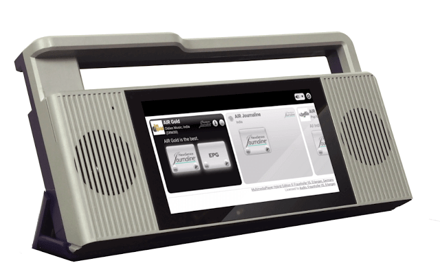
The PantronX Titus II is a yet-to-be-released portable Android tablet based SDR that we've been following since 2016. The device will feature a 100 kHz - 2 GHz tuning range, and software that focuses on HF digital DRM decoding, as well as DAB on VHF.
As you might be aware, we have joined up with Fraunhofer to include their MMPlayer app standard on Titus–what a difference a professional decoder, for both analog, DRM(+), and DAB(+), makes! MMPlayer is full featured even including reliable one way file downloads with DRM.
We are attempting also to license HD to include on the app for North America, making a truly worldwide receiver. Some deficiencies in our version of Android have caused issues as well as MMPlayer. All of which have caused delays leading to some serious business decisions – as you can imagine. You are correct that broadcasters have made large orders that will be fulfilled first. There are units in the field testing and such and continuing resolution of the software issues.
One of the issues that folks seem to have a hard time understanding is that we can not just build a few hundred or even thousands of units. Our minimum run is 10,000pcs! To do that everything has to be 100% – including the software. We simply will not ship units that are not 100%. Titus works, MMPlayer works – its that last 5% that takes the most time to resolve. These facts preclude any incremental production attempts. All that being said, we are very hopeful that the first production run is ready by last quarter of this year.
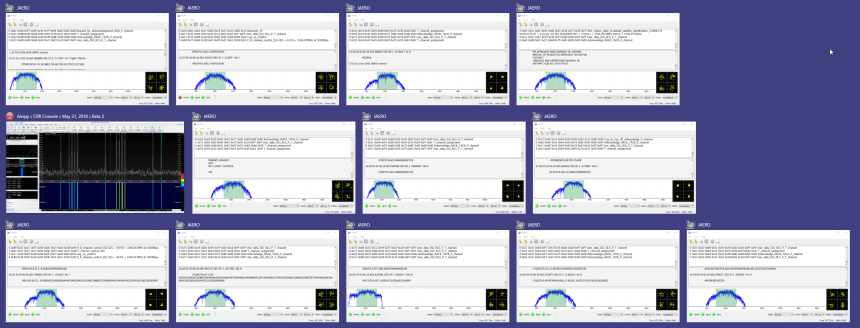
In a post uploaded last month we noted that Outernet was selling off some of their old L-Band satellite antennas cheaply. Nils Schiffhauser (DK8OK) decided to take advantage of the sale and bought one. Now Nils has created a blog post that shows how he's been able able to decode 12 L-Band AERO channels simultaneously with the Outernet L-band antenna, an Airspy R2 and SDR-Console V3. AERO is the satellite based version of aircraft ACARS, and it's L-band signals contain short ground to air messages like weather reports and flight plans. Multiple channels are often in use at any one time.
To achieve this Nils uses the multi-channel tuning capabilities of SDR-Console V3, which allows him to open up 12-channels, each tuned to a different AERO frequency. He then opens up 12 instances of the AERO decoder known as JAERO, and then uses VB-Cable to pipe the audio from each channel into a JAERO instance. Nils writes that the key to making JAERO run with multiple instances is to install JAERO into different folders on your PC, and give each JAERO.exe a unique file name like JAERO_1.exe.
He collects all the data into a program called Display Launcher and Nils notes that the whole set up has been stable digesting 54,000 messages over the last 24 hours.
Inspired by a low flying aircraft that kept waking his cat in the morning, Simon Aubury decided to use an RTL-SDR and ADS-B tracking software dump1090 to determine which plane was the culprit. This is all now standard stuff, however, Simon's software implementation and management of the received ADS-B data is quite unique, as he uses Apache Kafka, KSQL and Kibana as his tools for processing and visualizing the ADS-B data.
Apache Kafka is a 'distributed streaming platform', and KSQL enables real time processing of the data from Kafka. Kibana is a data visualization tool. Essentially these technologies are just ways to manage, process and digest in a human readable way large amounts of real time data coming into a database.
So with some clever database coding Simon was able to create a constantly updating dashboard in Kibana that plots aircraft positional heat maps, displays data such as spotted airlines and destination frequencies in a text cloud, and displays aircraft height data in a line graph. Finally using a database lookup and his gathered data Simon was able to determine that an A380 aircraft flying over his house was waking his cat in the morning.
SimpliSafe is an American DIY home security system company that claims over 2 million customers. Their system relies on 433/315 MHz ISM band wireless radio communications between its various sensors, control panels and remote controls. Back in 2016 we already posted about research from Dr. Andrew Zonenberg and Micheal Ossmann who showed that the SimpliSafe wireless communications are unencrypted, and can easily be intercepted, decoded, and spoofed. SimpliSafe responded to those concerns by downplaying them and mentioning that sophisticated hardware was required.
Adam began with some initial manual RF analysis with an RTL-SDR, and then later worked with rtl_433 dev Christian Zuckschwerd to add PiWM demodulation capability, which is the modulation used by SimpliSafe systems. Now Adam is able to easily decode the serial number, pin codes, and status codes transmitted by SimpliSafe sensors and key pads in real time with just an RTL-SDR.
This is very concerning as not only could a burglar easily learn the alarm disarm pincode, but they could also profile your behavior to find an optimal time to break in. For example if you arm your alarm before bed, and disarm in the morning your sleep schedule is being broadcast. It is also possible to determine if a particular door or window has been left open. With a tuned Yagi antenna Adam was able to receive signals from 200+ feet (60m) in free space, and 115 feet (35m) through walls.
In addition to the lack of encryption, Adam also discovered that the SimpliSafe system was susceptible to jamming attacks, and that the tamper detection system can be easily compromised. Adam has disclosed all concerns and findings to SimpliSafe who are aware of the problems. They assure him that next generation systems will not suffer from these flaws. But unfortunately for current generation owners, the hardware will need to be eventually replaced as there is no over the air update capability.
Over on GitHub dbdexter-dev has released a new lightweight and open source Meteor M2 demodulator. Meteor M2 is a Russian weather satellite that transmits images down in the digital LRPT format. This provides much higher resolution images compared to the NOAA APT signals. With an RTL-SDR, appropriate satellite antenna and decoding software it is possible to receive these images.
This new lightweight demodulator may be especially useful for single board PCs like the Raspberry Pi. Previously, on Linux GNU Radio based demodulators have been used, and GNU Radio isn't exactly a light weight piece of software. To use the software you first need to record an IQ file of the Meteor M2 LRPT signal, downsample the IQ file to 140 kHz (if required), then pass it into the demodulator. This will spit out an 8-bit soft-QPSK file which can be used with LRPTofflinedecoder (now known as M2_LRPT_Decoder) on Windows or meteor_decoder on Linux to generate an image.
An Example LRPT Image Received with an RTL-SDR from Meteor-2 M2.