Video Tutorial: Setting up DMR Decoding with SDR#, DSD+ and an RTL-SDR

Over on YouTube user Tech Minds has uploaded a useful video which shows how to set up DMR decoding with SDR#, VB-Cable, DSD+ and an RTL-SDR dongle. He also uses the DSD plugin for SDR# which makes controlling the command line DSD+ software a little easier. If you are interested we also have a short tutorial on DMR/P25 decoding available here. The video starts from downloading and installing the software, and explains every step very carefully, so it is a very good starting video for beginners.

DMR (aka MotoTRBO or TRBO) is a digital voice protocol used by Motorola radios. Software like DSD+ is required to listen to it, but it can only listen in if the signal is unencrypted.

Tech Minds has also uploaded several other tutorial videos to his channel over the last few months including guides on how to set up the ham-it-up upconverter, ADS-B tracking, using a Raspberry Pi to create a FM transmitter and more.

How To Setup SDR # Sharp To Decode DMR Digitial Using DSD Plus And An RTL SDR Receiver on Windows 10

Visual Tuner Knob Plugin for SDR#

Thank you to Eddie MacDonald for submitting his new SDR# plugin to us via our forums. Eddie's plugin is called the 'Tuner Knob Plugin', and simply enables a visual tuner knob on the screen for adjusting the frequency. This plugin could be useful especially for those running SDR# on touchscreen tablets or laptops. To install the plugin copy the .dll file to the SDR# directory and copy and paste the magicline.txt into the plugins.xml file. We tested the plugin on our PC and found it to run well.

We have uploaded the plugin here for all to download. Note: Updated plugins now available at https://sdrplugins.com.

Eddie writes about the plugin:

Programming the plugins is not so easy considering their is very little documentation and few examples on the net. There may be a few bugs I have not caught (but i hope i have caught them all.)

This DLL was compiled and tested on a Windows 7 x64 machine and the DLL is compiled for both x86 and x64 platforms. I have tested it on SDR# Version v1.0.0.1635

I am not certain which previous versions it may or may not run on. However, being built on the 4.6 .Net framework it should work with Win7 on.

I built this plugin because i got tired of holding down buttons and waiting for the frequency changes. I figured this was a simpler method (even though some people hate rotary style controls on windows) It works exceptionally well with a touch screen.

As previously mentioned in the forum post I created the 'remote' to test my programming for future plugins for DSP

While some may not find a use for the remote I made it this way for my wife who like to cruise the dial and just see what she can pick up.

Tuner Knob Plugin for SDR#

Some more information about the Airspy HF+ R3 Bypass Modification

At the beginning of this month we posted a review by Bjarne Mjelde who reviewed the MW DXing performance of the Airspy HF+. One thing he found was that by performing a simple capacitor bypass modification, the performance of the HF+ below 15 MHz could be significantly improved. Over on the SWLing blog we've seen a post that gives a bit more information for those wanting to perform the R3 bypass modification on their HF+'s. There Yousseff, head of the Airspy team wrote:

During the early phases of the design R3 was a place holder for a 0 ohms resistor that allows experimenters to customize the input impedance. For example:

  • A 300 pF capacitor will naturally filter the LW/MW bands for better performance in the HAM bands
  • A 10µH inductor would allow the use of electrically short antennas (E-Field probes) for MW and LW
  • A short (or high value capacitor) would get you the nominal 50 ohms impedance over the entire band, but then it’s the responsibility of the user to make sure his antenna has the right gain at the right band
  • A custom filter can also be inserted between the SMA and the tuner block if so desired.

R3 and the nearby resistors have been intentionally left outside of the RF shield, and their size was picked to be big enough to allow anyone to play with them. You will notice the size difference with the rest of the components.

In general, unless one knows what he’s doing, it’s not recommended to alter a working system. “If it’s working, don’t fix it”. But, we are hobbyists, and not doing so leaves an uncomfortable feeling of something unachieved. Most brands addressing the hobby market leave some tweaks and even label them in the PCB.

The main purpose of the HF+ is the best possible performance on HF at an affordable price. This is to incite HAMs to get started with this wonderful technology while using an SDR that isn’t worse than their existing analog rig.

The MW/LW/VLF crowd may have slightly different requirements, but that can be addressed by shorting a resistor.

The HF+ Mod (Edited by Bjarne, original photo by Nils Schiffhauer)

Running a NAS, Torrentbox and ADS-B RTL-SDR Server all on the same Raspberry Pi 3

Most readers are familiar with the Raspberry Pi 3 and how it can be used with RTL-SDR applications such as ADS-B reception. However, one does not need to dedicate an entire Pi 3 to a single task as they are more than powerful enough to run multiple applications at once.

Over on his blog 'Radio for Everyone' Akos has uploaded a tutorial that shows how he set his Raspberry Pi 3 up as a simultaneous Network Attached Storage (NAS), Torrentbox  and ADS-B server. A NAS is simply a hard drive or other data storage device that can be accessed easily over a network instead of having to be connected directly to a PC. A torrentbox is a device such as a Raspberry Pi 3 running torrent software so that you can download torrent files 24/7 without needing a PC on all the time.

Akos' tutorial shows how to set everything up from scratch, starting from writing the Raspbian SD Card and connecting to it via SSH. He then goes on to show how to install the torrent software, set up the NAS and finally set up ADS-B reception.

Pi 3 as a NAS, torrentbox and ADS-B server.

DSP Illustrations: Learning DSP with a Soundcard SDR

DSP Illustrations is an online course that aims to explain complex digital signal processing (DSP) concepts visually instead of on a purely theoretic and mathematical level. Most of the content appears to be free, but some premium content requires payment.

One premium course that they've recently released is titled "Using your Soundcard as a Software-defined radio". In this course they use a standard PC sound to transmit (with the speakers) and receive (with a microphone) audio signals. All the DSP code is produced in Python and the course aims to walk you through all the concepts shown below.

  • baseband transmission of real-valued signals
  • passband transmission including up- and downconversion
  • modeling the audio channel as an LTI system for reproducable simulations
  • eye diagram drawing
  • symbol timing recovery
  • channel coding
  • definition and implementation of a frame structure, including header, payload and checksum
  • integration of the wireless transmission into a UDP data stream

Although the "SDR" isn't using radio frequencies, the exact same DSP concepts that apply with audio also apply to radio. So this can be a cheap way to get hands on DSP experience without the cost of needing to own a transmit/receive capable SDR.

This course costs about US$20, but the first three chapters are free.

Using a soundcard to study wireless communications.

Understanding the Fourier Transform: Video Tutorial from 3Blue1Brown

The Fourier Transform is a fundamental concept when it comes to digital signal processing (DSP) and thus understanding how software defined radios like the RTL-SDR work. It is the key bit of maths behind the RF/waterfall spectrum displays and frequency selection features used on your SDR software. In basic terms all the Fourier Transform does is take a signal (for example an RF signal from an antenna, or a sound sample), and break it down into its component frequencies. This allows us to see each individual frequency spike in the RF/waterfall spectrum display in programs like SDR# from the mash of signals that arrive at the antenna. But understanding how the Fourier Transform does this can be a little tricky to understand.

3Blue1Brown is a very successful YouTuber whose channel is all about explaining complex mathematical concepts in an animated and easy to digest format. His latest video explains the Fourier Transform, and is a great starting point for those trying to learn DSP concepts. He focuses on audio frequencies as that is the most intuitive, but the exact same concepts can be applied to radio frequencies.

But what is the Fourier Transform? A visual introduction.

Receiving Satellite TV Beacons with an RTL-SDR and LNB

Thank you to an anonymous contributor for sharing his experiences with trying to receive satellite TV beacons with his RTL-SDR. Satellite TV is typically up at 10.7 to 11.7 GHz which is far too high for an RTL-SDR to receive. So to receive these frequencies with the RTL-SDR he uses a satellite TV LNB (an LNB is essentially a downconverter and satellite dish feed), a DIY Bias T and a 90 cm dish. He writes:

Almost all television satellites have a special frequency for transmitting a beacon signal. The beacon signal is a reference signal with fixed frequency, power and [maybe] without modulation that is sent usually by satellites. One of the most important techniques used for satellite wave propagation studies is satellite beacon signal measurement. (http://eej.aut.ac.ir/article_433.html)

I used an universal LNB, DIY bias-T and a fixed 90cm dish pointed at 26 degrees East. By connecting 18 volts DC to LNB I am able to activate the 9750 Mhz local oscillator and horizontal operating mode of LNB.

Means that anything received with LNB between 10.7-11.7 GHz can be easily seen in 950-1950 MHz range, using RTL-SDR.

I used this set-up to receive the GEO satellites beacons. A list of beacon frequencies" http://frequencyplansatellites.altervista.org/Beacon-Telemetry_Europe-Africa-MiddleEast.html.

It is useful for measuring attenuation caused by heavy rain in Ku band or accurate dish positioning or even measuring frequency drift in LNB local oscillator caused by wind and temp change during a timespan.

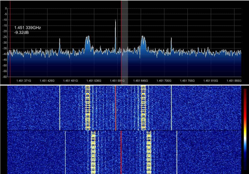
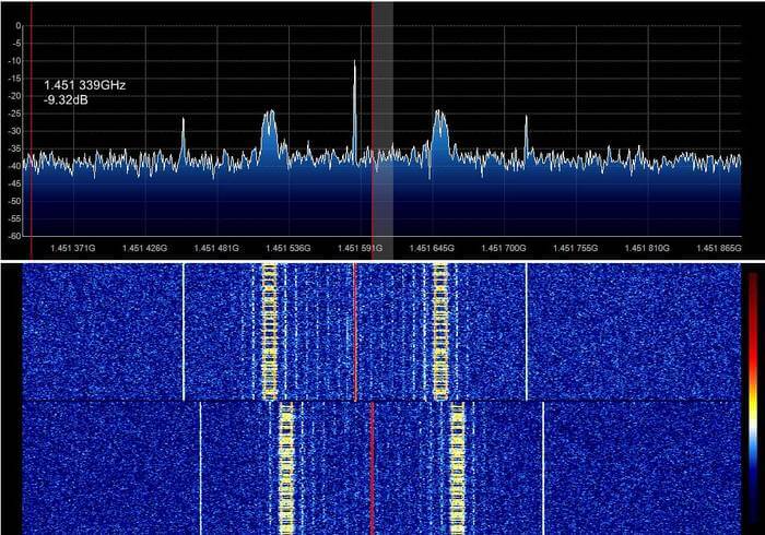
It seems that the right signal is Eutelsat 21B and left Es'hail 1.

In picture 4 signal captured immediately after turning on LNB. but all others are captured after at least 5 hours of warming up.

MAYBE oscillator needs a stabilize time or temp change may caused the drift.

If you are interested in receiving these beacons, Daniel Estevez has also performed similar experiments with his RTL-SDR and an LNB as well, and has written about it on his blog.

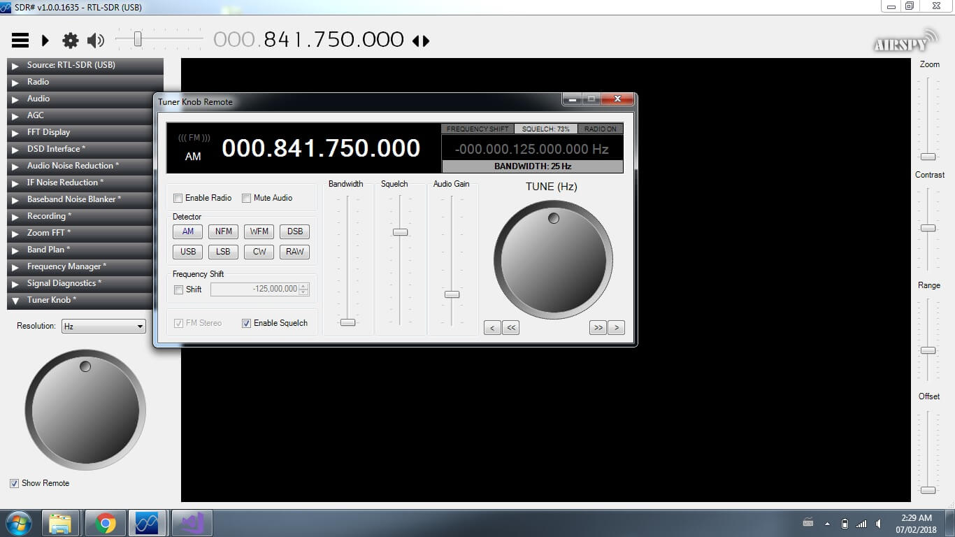
Below we show some images of beacons shown in SDR# that the anonymous contributor received with his setup.

The K9AY Loop Antenna: A Directional E-H Antenna for HF

Thank you to Frank Sessink (PA0FSB) for submitting to us his document describing the K9AY loop antenna (pdf), which is the antenna that he successfully uses with his RTL-SDR for HF reception. The antenna combines magnetic (H) and electric (E) field reception in order to create a directive radiation pattern. Frank extends the idea by showing a method that can adjust the directivity electrically with some simple resistor switching.

The antenna that I use is for medium wave DX, specially to receive MW from USA here in Europe/The Netherlands. The antenna is a combination of a magnetic loop and a sense antenna for the E-field. The magnetic loop is directive, but has no front-rear ratio. The E-field antenna has omnidirectional sensitivity. The combination, in correct phase and amplitude, results in a front-rear ratio of more than 25 dB over the frequency range from 500 kHz to around 3 MHz. Higher frequency makes no sense, since skywave signals distort the ground wave directivity pattern.

A simple modification is used as directional antenna with remote control: two orthogonal loops that combine E and H-field in a simple way. I can make 8 selectable directions.

The full document is available here in PDF format.

The K9AY E-H HF Antenna