Earlier in the month we posted about Adrian M’s video that showed his QRadioLink software running on Android with an RTL-SDR. QRadioLink is a digital amateur radio voice decoder and encoder, that currently supports modern digital voice codecs like Codec2 and Opus. It’s compatible with a wide range of SDRs including the RTL-SDR, as well as TX capable SDRs for transmitting.
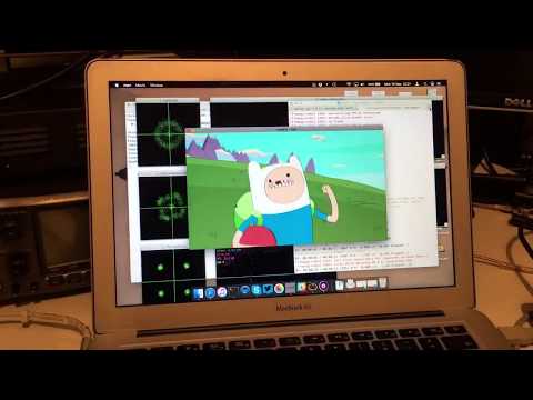
Over on YouTube Adrian M has recently uploaded a new video showing a comparison of QRadioLink receiving SSB, NFM, Codec2 and Opus voice signals at the same initial power levels. The results show that the digital modes are generally much clearer and static free even at low TX levels. He writes:
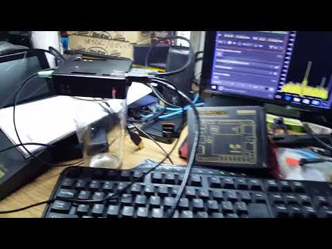
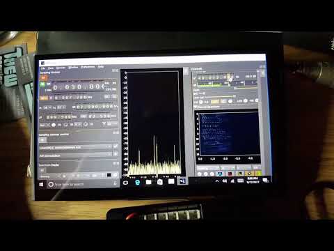
The Linux SDR transceiver application QRadioLink uses here an RTL-SDR dongle for reception. The QRadioLink transmit chain is using an USRP B200 with output power set at about half the maximum. The Codec2 digital mode works down to a low CNR (6 dB) where even SSB is hard to copy. The Opus mode provides good voice quality at a level where analog narrow FM is noisy. The code for QRadioLink is fully open-source, licensed under GPLv3, and can be found on Github, where it’s undergoing development. Bug reports, patches and suggestions are welcome.
Over on our store we now sell our dongles with a receive only dipole antenna kit that replaces the older magnetic whip style antennas from the previous kit. This was done for a few reasons
We believe that the dipole kit is much more versatile and will enable beginners to get better reception straight away
Magnets of any type are difficult to ship as they are not allowed by many airmail carriers.
While the magnetic whip still works perfectly fine, the dipole kit should make it easier to get the antenna outside or in a better position away from noisy computers/electronics, and it also allows for a simple v-dipole configuration for satellite reception.
The units are currently in stock at our Chinese warehouse either bundled with an RTL-SDR or as an individual antenna set.
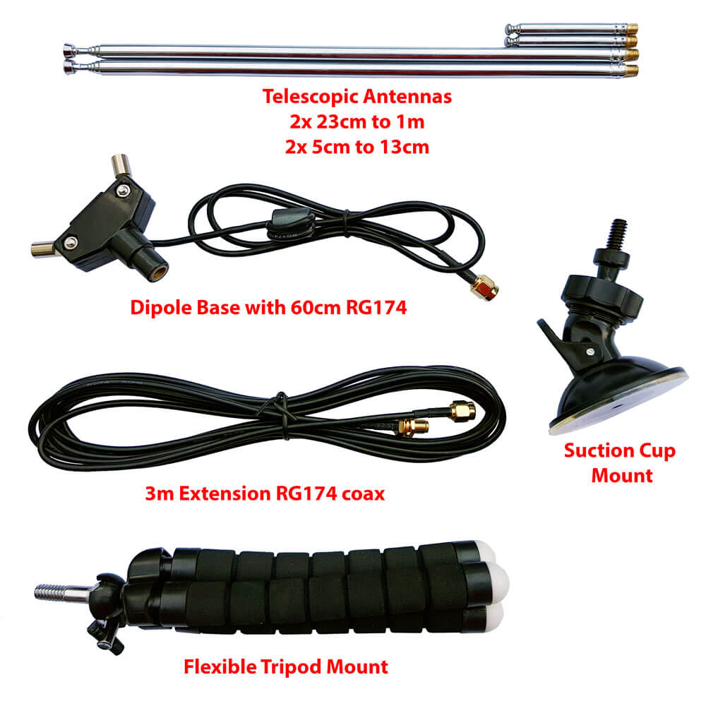
This post is a guide on how to use the dipole antenna set in various configurations. First we'll show and explain about what's included in the set:
1x dipole antenna base with 60cm RG174 cable and SMA Male connector. This is the dipole base where the telescopic antennas connect to. The short run of RG174 is decoupled from the base elements with a ferrite choke. This helps to prevent the feed line from interfering with the dipole radiation pattern. The dipole has a 1/4 inch female screw on the bottom, which allows you to use standard camera mount products for mounting.
1x 3 meter RG174 coax cable extension. This coax cable extension allows you to mount the antennas in a place that gets better reception. E.g. outside on a window, or higher up.
2x 23cm to 1 m telescopic antennas. The telescopic dipoles are detachable from the dipole base via a M5 thread which allows for greater portability and the ability to swap them out. These long telescopic antennas cover VHF to UHF.
2x 5cm to 13cm telescopic antennas. These smaller antennas cover UHF to 1090 MHz ADS-B, and even still work decently up to L-band 1.5 GHz frequencies.
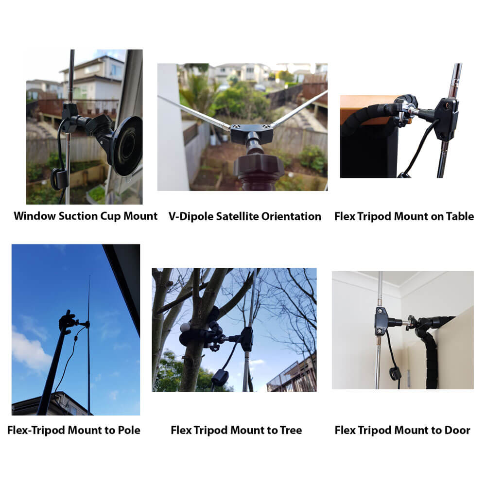
1x flexible tripod mount with 1/4" male screw. This piece allows you to mount the dipole on a variety of different locations. E.g. a pole, tree branch, desk, door, window sill. The legs of the tripod are bendy and rubberized so can wrap securely around many objects.
1x suction cup mount with 1/4" male screw. With this mount you can mount the dipole on the outside of a window, on a wall, car roof/window, or on any other smooth surface. To use first clean the surface with window cleaner or isopropyl alcohol. Then place the suction cup on the cleaned surface and close the lever to activate the suction.
What's included in the new Dipole kit
Dipole Orientation
Signals are normally transmitted with either horizontal, vertical or right hand/left hand circular polarization (RHCP/LHCP). This is essentially the 'orientation' of a signal, and an antenna with the same polarization should be used too for best performance. A dipole can be used in either vertical or horizontal polarization, just by orienting it either vertically or horizontally.
If you mismatch vertical and horizontal polarization or RHCP and LHCP you'll get an instant 20dB loss. If you mismatch vertical/RHCP, vertical/LHCP, horizontal/RHCP, horizontal/LHCP you'll only get a 3dB loss.
For vertical polarization, in theory it does not matter which way around you orient the antenna as long as it's vertical. However in practice, you may get slightly better results by having the element connected to the center coax conductor pointing UP. You can confirm which element is connected to the center conductor by temporarily removing the black lid on the dipole base (it can be easily pried off with a nail or flat head screwdriver).
There are also ways to optimize the radiation pattern with dipoles. For example for LEO VHF satellites you can use a V-dipole configuration. You can also make a somewhat directional antenna by using a bent dipole configuration. Some more examples of dipole configurations can be found on KK4OBI's page on bent dipoles.
Terrestrial Signal Reception
Most signals broadcast terrestrially (on Earth) are vertically polarized.
To use the dipole for vertically polarized signals, all that you need to do is orient the elements vertically (up and down).
In theory there is no up and down for the dipole when used in the vertical orientation. However in practice you may find slightly better performance when the 'active' element points up. The active element is the one connected to the center conductor. You can check which element is connected to the center conductor by removing the top cap on the dipole base. This will let you look inside at the connections.
Satellite Reception
The dipole can be used in a V-Dipole configuration for polar orbiting satellite reception. See Adam 9A4QV's post where he wrote about how he discovered that it was possible to use dipoles in this configuration for excellent satellite reception. The idea is to use the dipole in horizontal polarization. This gives 3dB loss on the RHCP satellite signals, but also nicely gives 20dB loss on terrestrial signals which could be overloading your RTL-SDR.
For 137 MHz satellites like NOAA and Meteor M2 extend the larger antenna elements out to about 53.4 cm each (about 2.5 sections). Angle the dipole so it is horizontal and in a 'Vee' shape, at about 120 degrees. Place the dipole in the North-Source direction.
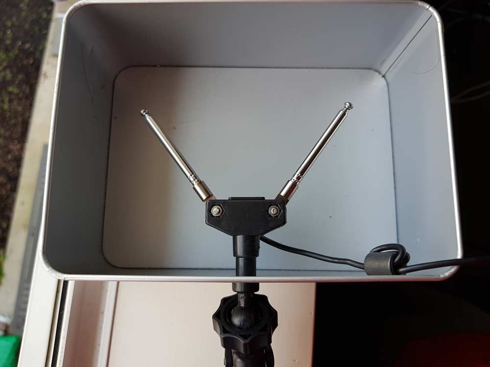
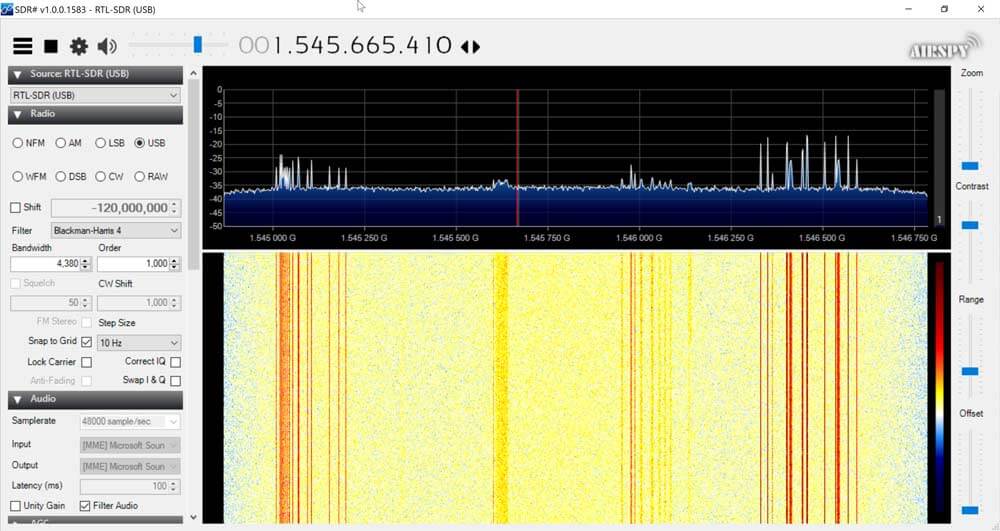
With an appropriate L-band LNA like the Outernet LNA the dipole can also somewhat work to receive L-band satellites. Using the smallest antenna collapsed, use a V-dipole configuration and point it towards the L-band satellite. Ideally use a reflector too. In the image below we used a simple cookie tin as a reflector. A hole was drilled into the center and the mount used to clamp in the antenna. This together with the Outernet LNA was enough to receive AERO and STD-C.
Choosing the Antenna Element Length
Like with the whip you can use an online calculator to calculate the optimal length for your frequency of interest. We recommend this dipole calculator. The exact length does not matter too much, but try to get the lengths as close to what the calculator says as you can. With the dipole you want both elements to be the same length.
In reality extending the antenna to almost any random length will work just fine for most strong signals. But if you're really trying to optimize those weak signals you'll want to fine tune the lengths.
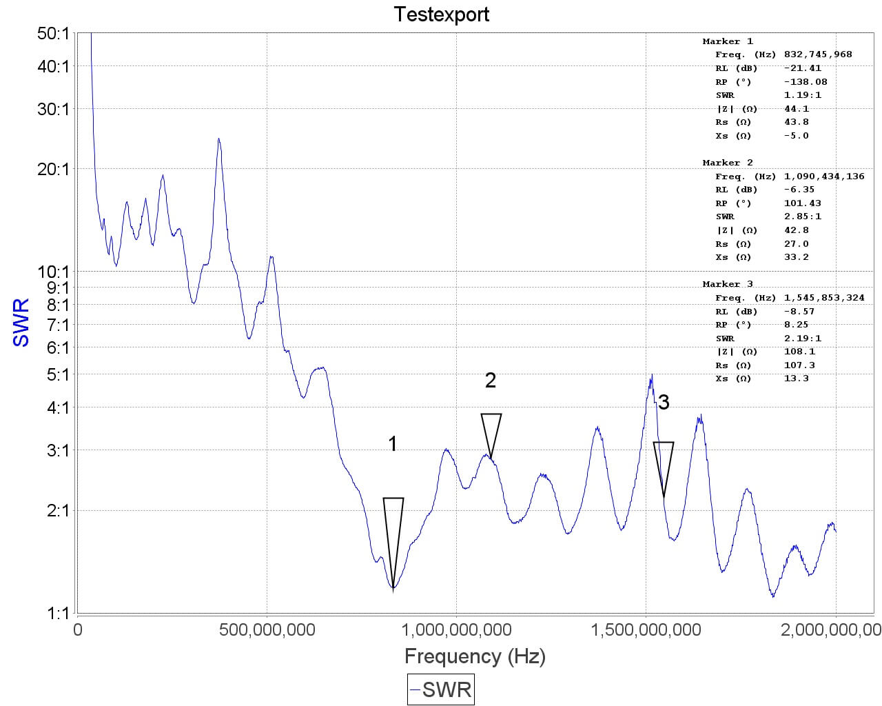
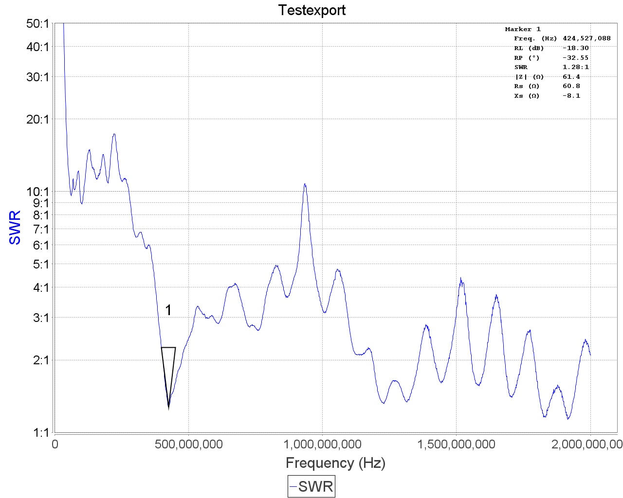
Basically the longer the antenna, the lower it's resonant frequency. The shorter the antenna, the higher the resonant frequency. You want to be close to the resonant frequency. Remember that there is about 2cm of metal inside the antenna itself which needs to be added on. Below is a cheat sheet for various lengths and frequencies. Note that the length refers to the length of one side of the dipole only (e.g. the length that you need to extend each element out to).
Large Antenna, 5 Sections, 100cm + 2cm is resonant @ ~70 MHz
Large Antenna, 4 Sections, 80cm + 2cm is resonant @ ~87MHz
Large Antenna, 3 Sections, 60cm + 2cm is resonant @ ~115 MHz
Large Antenna, 2 Sections, 42cm + 2cm is resonant @ ~162 MHz
Large Antenna, 1 Section, 23cm + 2cm is resonant @ ~ 285 MHz
Small Antenna, 4 Sections, 14cm + 2cm is resonant @ ~445 MHz
Small Antenna, 3 Sections, 11cm + 2cm is resonant @ ~550 MHz
Small Antenna, 2 Sections, 8cm + 2cm is resonant @ ~720MHz
Small Antenna, 1 Section, 5cm + 2cm is resonant @ ~1030 MHz.
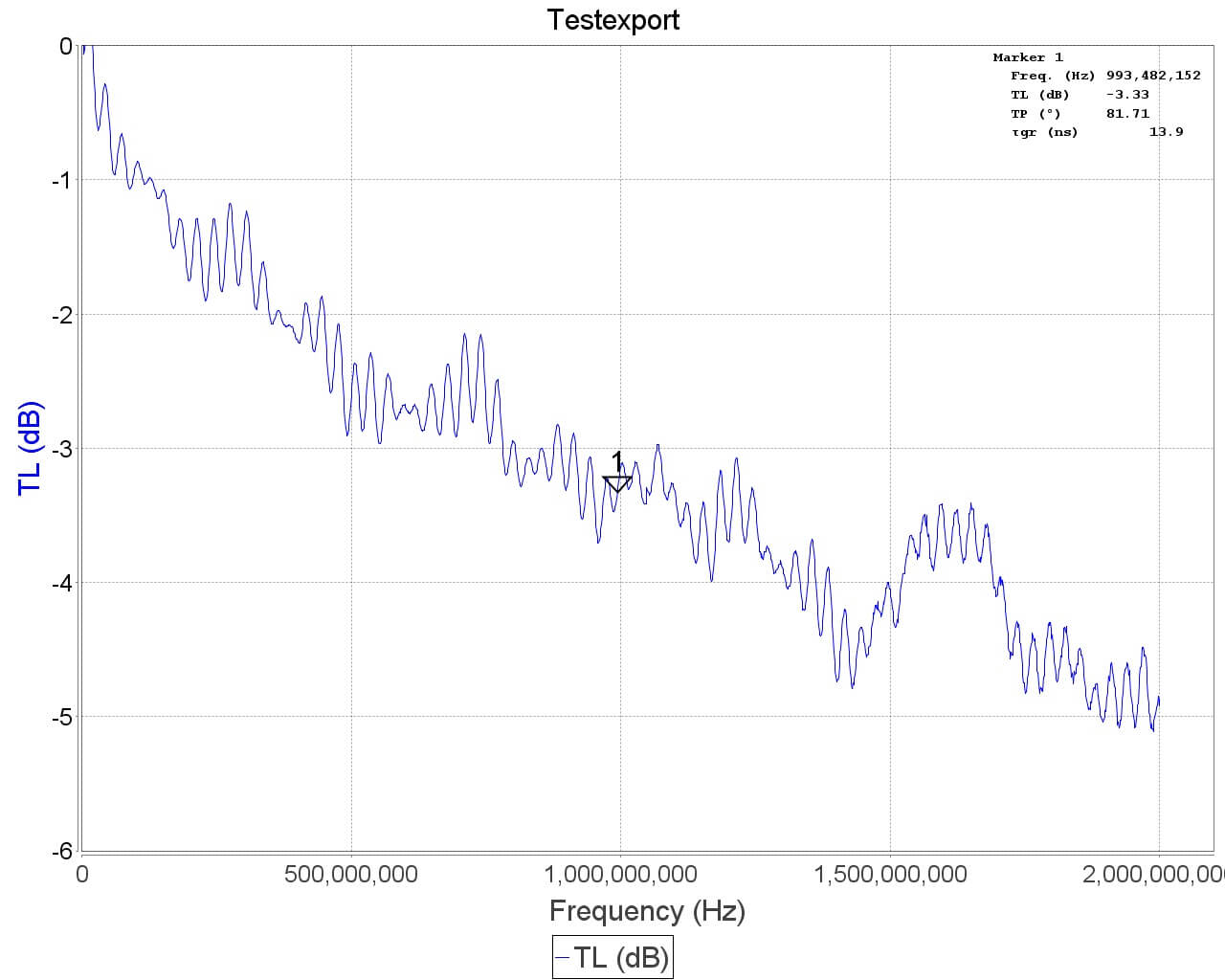
See the SWR plots at the end for a more accurate reading of the resonance points. But in most cases no matter what you extend the length to the SWR should be below 5 at most frequencies which results in 2.5 dB loss or less. More accurate info on VSWR loss graphs can be found in this document from the ARRL "Understanding SWR by Example" (pdf).
Using the Mounts
The suction cup mount allows you to easily place the antenna on a window, or any smooth surface. To use it first clean the surface thoroughly with isopropyl alcohol or glass cleaner. Then apply the suction cup and close the lever to lock it in place. The lever requires some force to push down, and this ensures a strong grip. You can then angle the antenna in the orientation that you need using the ball socket. Once in place close the ring to lock the ball socket in place.
The flexible tripod mount is useful to mounting the dipole to almost everything else. Including tables, doors, poles, trees etc. The legs of the tripod have a flexible metal wire inside and rubber sheath so they can be bent into a position to grip almost anything.
Some examples of how to use the mounts.
Note that the mounts and RG174 extension allow you to more easily use the dipole antennas outside or in a better indoors position (e.g. on a Window). But please note that like our older magnetic whip we do not recommend permanently mounting this antenna outdoors. This antenna is designed to be a portable antenna that you put up and take down at the end of the day - not for permanent outdoor mounting. It is not protected against water, not grounded so cannot handle a lightning strike and could be damaged with dirt and grime build up. For permanent outdoor mounting you could conceivably fill the inside and hinges of the dipole with silicon putty or maybe even hot glue and ground the antenna yourself, but we have not tested this. The stainless steel antennas won't rust, but dirt and grime could gum up the collapsing mechanism.
Tightening the hinge
Once you've got the orientation of the dipoles the way you want, you might want to tighten the hinge so the elements don't move so easily anymore. To do this simply take a small screwdriver and tighten the screw on the hinge.
ESD Bleed Resistor
Note that our older antennas had a 100kOhm ESD bleed resistor between the two elements. This is no longer the case on newer models. The purpose of the resistor was to slowly bleed any ESD buildup to ground.
We decided to improve ESD protection on the dongle instead, so the ESD bleed resistor is not longer required and is now omitted on newer productions.
Sample VSWR Plots
Other Notes
Note that this is NOT an antenna designed for TXing. It is an RX antenna only. So please do not TX with it unless you really know what you are doing as you could damage your TX radio.
Thanks to the team of Robotics company Servosila for sharing the following press release with us which describes how their new EOD robot makes use of SDR technologies for electronic warfare.
We also wrote back to them and asked for a bit more information on the SDRs used. They wrote that there are two SDR options available for the EOD robot. Option one uses the Ettus Research USRP B205mini-i, and option two uses the HackRF One. This provides a good trade off between cost and functionality.
Servosila introduces Mobile Robots equipped with Software Defined Radio (SDR) payloads
Servosila introduces a new member of the family of Servosila “Engineer” robots, a UGV called “Radio Engineer”. This new variant of the well-known backpack-transportable robot features a Software Defined Radio (SDR) payload module integrated into the robotic vehicle.
“Several of our key customers had asked us to enable an Electronic Warfare (EW) or Cognitive Radio applications in our robots”, – says a spokesman for the company, “By integrating a Software Defined Radio (SDR) module into our robotic platforms we cater to both requirements. Radio spectrum analysis, radio signal detection, jamming, and radio relay are important features for EOD robots such as ours. Servosila continues to serve the customers by pushing the boundaries of what their Servosila robots can do. Our partners in the research world and academia shall also greatly benefit from the new functionality that gives them more means of achieving their research goals.”
Coupling a programmable mobile robot with a software-defined radio creates a powerful platform for developing innovative applications that mix mobility and artificial intelligence with modern radio technologies. The new robotic radio applications include localized frequency hopping pattern analysis, OFDM waveform recognition, outdoor signal triangulation, cognitive mesh networking, automatic area search for radio emitters, passive or active mobile robotic radars, mobile base stations, mobile radio scanners, and many others.
A rotating head of the robot with mounts for external antennae acts as a pan-and-tilt device thus enabling various scanning and tracking applications. The neck of the robotic head is equipped with a pair of highly accurate Servosila-made servos with a pointing precision of 3.0 angular minutes. This means that the robot can point its antennae with an unprecedented accuracy.
Researchers and academia can benefit from the platform’s support for GnuRadio, an open source software framework for developing SDR applications. An on-board Intel i7 computer capable of executing OpenCL code, is internally connected to the SDR payload module. This makes it possible to execute most existing GnuRadio applications directly on the robot’s on-board computer. Other sensors of the robot such as a GPS sensor, an IMU or a thermal vision camera contribute into sensor fusion algorithms.
Since Servosila “Engineer” mobile robots are primarily designed for outdoor use, the SDR module is fully enclosed into a hardened body of the robot which provides protection in case of dust, rain, snow or impacts with obstacles while the robot is on the move. The robot and its SDR payload module are both powered by an on-board battery thus making the entire robotic radio platform independent of external power supplies.
Servosila plans to start shipping the SDR-equipped robots to international customers in October, 2017.
About the Company Servosila is a robotics technology company that designs, produces and markets a range of mobile robots, robotic arms, servo drives, harmonic reduction gears, robotic control systems as well as software packages that make the robots intelligent. Servosila provides consulting, training and operations support services to various customers around the world. The company markets its products and services directly or through a network of partners who provide tailored and localized services that meet specific procurement, support or operational needs.
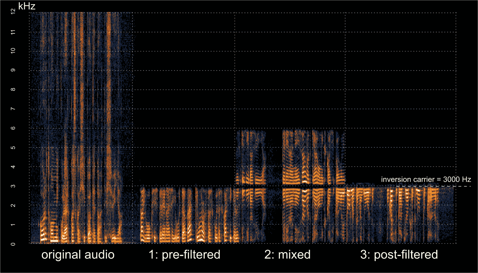
In early September we posted about Oona Räisänen’s deinvert which is a tool that can be used to unscramble voice audio that has had voice inversion scrambling applied to it. Voice inversion works by scrambling the voice frequencies so that a simple eavesdropper will have trouble listening in. A special descrambling radio is required to listen in. This provides very little real security, but may be enough to stop people with cheap scanners from listening in. Oona’s deinvert tool allows us to take a scrambled audio sample recorded with an RTL-SDR or any other radio and decramble the inversion.
In her latest blog post Oona explains how her deinvert software works and how it can also be used to decode the more difficult split-band inversion technique. She also writes that at the default quality level, the deinvert software is fast enough to run in real time on a Raspberry Pi 1.
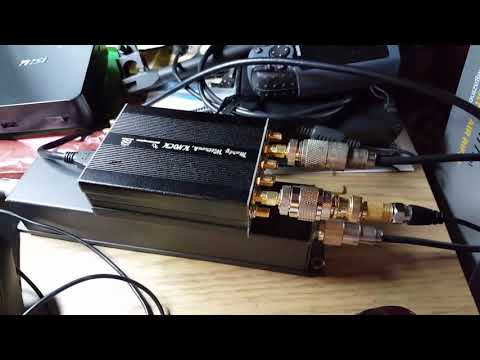
Just last week we posted about how Marty Wittrock was able to get his LimeSDR receiving perfectly on his LattePanda mini Windows 10 PC with SDRAngel. Now Marty has uploaded a new video which shows the LimeSDR running on the LattePanda and SDRAngel again, but this time transmitting 40m LSB voice. At this stage Marty is well on his way to creating a fully portable LimeSDR based ham transceiver. He writes about his setup:
Setup: LattePanda Win10/64-bit, LCD, Capacitive Touchscreen, LimeSDR and SDRAngel Win32 with a transmit device loaded…Also using a USB 2.0 audio device to make the microphone and speaker audio connections…WORKS GREAT..!!
The LimeSDR is a RX and TX capable SDR with a frequency range of 100 kHz – 3.8 GHz, bandwidth of up to 61.44 MHz, 12-bit ADC and 2×2 RX/TX channels. Recently the LimeSDR team have been crowdfunding for their new ‘LimeSDR Mini’ which is a smaller and cheaper feature reduced version of the standard LimeSDR. While all the early bird $99 USD units have been sold out, they are still available at the $139 USD price. Currently the crowdfunding campaign has already reached it’s $100,000 USD target with 35 days left.
One important ‘feature reduction’ to note is that the LimeSDR Mini can only tune down to 10 MHz, so it may not be as useful as the full $289 USD LimeSDR for creating a SDR based ham transceiver like what Marty is doing.
LimeSDR, LattePanda, and SDRAngel Transmitting on 40m LSB Voice
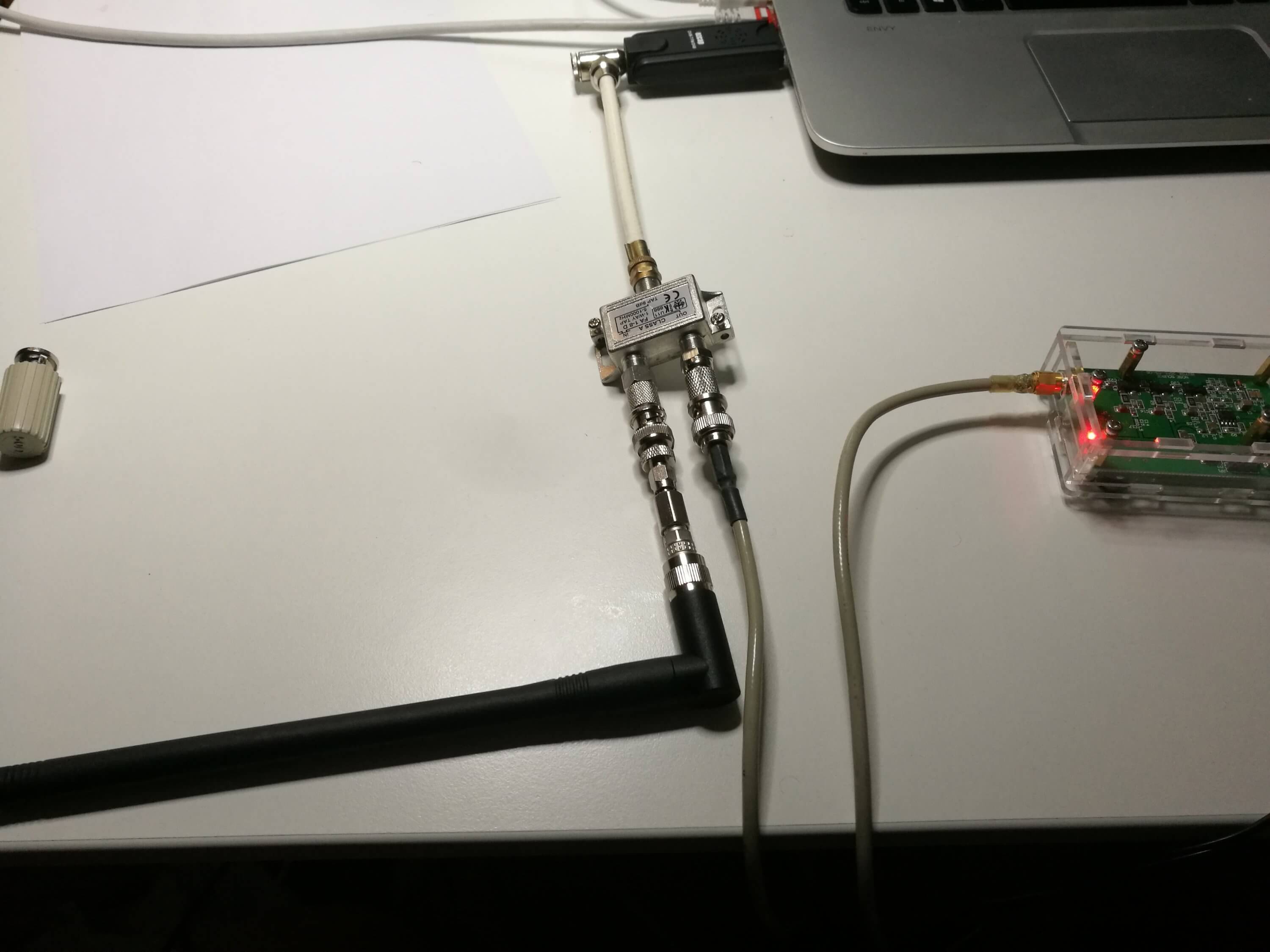
However, being without a directional coupler Tomi looked for other options and realized that cheap TV antenna network taps are also directional couplers. Taps are commonly used with Cable and Satellite TV installations to split a signal from an antenna over multiple TVs. They are designed as directional couplers to ensure that unwanted signals do not feed back into the antenna system and so that there is a pass through port to continue the strong signal down a long cable.
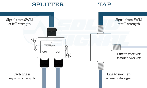
Note that there is a difference between a tap and a splitter. Taps are used when multiple devices need a signal over a long run of cabling. A splitter divides the signal strength by the number of out ports and can feedback unwanted signals into the system.
Taps vs. Splitter Example (Source: http://forums.solidsignal.com/showthread.php/5843-Solid-Signal-s-WHITE-PAPER-The-NEW-DIRECTV-Residential-Experience)
In his tests Tomi found that TV taps worked acceptably well to determine the resonance frequency of an antenna that he was testing. Taps can be found for as cheap as $2 on sites like eBay, although for some listings it is unclear over what frequency range they work well at as sellers assume that they will be used for TV frequencies.
Over on YouTube Christopher Bridges has uploaded a video showing him using a PlutoSDR and a GNU Radio program to transmit a DVB-S signal, which is then received with an RTL-SDR. DVB-S is a digital video broadcasting standard designed for satellite transmissions and digital amateur television video (DATV) also uses DVB-S in the 1.2 GHz amateur band. In this example the PlutoSDR transmits at 1.28 GHz.
Chris uses the rtl_sdr command line software to receive the raw IQ data at 1 MSPS, and then uses the leandvb software to decode the raw IQ file directly into a video file.
If you’re interested in TXing DVB-S/DATV but don’t have a transmit capable SDR, then we note that even a Raspberry Pi just by itself can be used to transmit it with rpidatv.
Linux gnuradio QPSK DVBS PlutoSDR + rtl MacBook leansdr
Thanks to Marty Wittrock for sharing with us his latest news about his experiences with the LimeSDR. Over on YouTube he’s uploaded a video showing that the LimeSDR can run perfectly on a ‘LattePanda‘ which is a full Win10 64-bit PC in a Raspberry Pi sized package. The one Marty uses costs about $209 with a fully activated Windows 10 licence and has 64G eMMC memory, a 1.44 GHz CPU and 4GB of RAM. The cheaper version with 2GB of RAM and 32GB eMMC memory only costs $119 USD. Of interest is that the LattePanda also comes with an Arduino co-processor for various GPIO projects, which could be useful for switching in and out various radio blocks like filters and LNAs.
In his video Marty shows that the SDRAngel software run the LimeSDR smoothly on the LattePanda, and he demonstrates receiving the 30M band. He writes:
Ladies and Gentlemen may I present to you: The LimeSDR operating on receive on the 30m Shortwave Band using SDRAngel running on a Windows 10, 64-bit, 4G (RAM) 64G (FLASH) operating at 1.8 GHz on a LattePanda – – THE SMALLEST WINDOWS 10 PC ON EARTH..! No kidding, this makes my MSI ‘hockey puck’ PC look monstrous…The LattePanda is about the same size as my LimeSDR and a VERY POWERFUL little PC, too…I’m INCREDIBLY impressed with this tiny PC…This Single Board Computer also has an integrated Arduino processor such that all the bandswitching and other functions required to make a Software Defined Transceiver will be very trivial to add-in…The ‘proof of concept’ is complete – – this shows that it CAN BE DONE to make the LimeSDR into a compact, wideband Software Defined Transceiver that can be run on a car battery if needed…Watch the video and see for yourself…CHEERS..!
LimeSDR With LattePanda Win10 64-bit
In a second newer video he demonstrates the system running on a 7″ LCD touchscreen. He writes:
Here’s a follow-up YouTube video I did when I laced-up the LattePanda to a 7″ LCD and the companion Capacitive Touchscreen for the LimeSDR. This thing is awesome and very compact – it’s amazing. I’m planning to take those same components and mount them into a walnut case that I’m getting made from furniture-grade wood from Amana. The case will be sloped and will have enough room to put the LattePanda, LimeSDR, USB 3.0 hub, and *maybe* the PA – but I have to think that the PA will be outboard along with the Bandpass Filter Card assembly, too. I am planning to make a preselector/receive preamplifier for the LimeSDR that will reside in the case, too. The LattePanda not only has the Intel CherryTrail processor there for Windows, but it also has an integrated Arduino processor on the board along with the Arduino development software and the GPIO on the LattePanda to drive the BPF, PA, T/R switching, and the receive preamplifier/preselector/filter. No kidding – when this is all done this thing is going to be unstoppable. SDRAngel is open source so adding the communications for band switching will not be hard to do between Edouiard’s source in Win32 and to the Arduino through DLL calls. I’m even giving some serious thought about how LimeSDR-Mini will be included as an alternative with an even smaller footprint for this.
LimeSDR and LattePanda Win10, 64-bit running SDRAngel with 7" LCD/Touchscreen
Looks like the LimeSDR is slowly starting to all come together as a fully usable system for ham radio thanks to the efforts of people like Marty. Remember that Lime are currently crowdfunding for their latest LimeSDR Mini product, which is a cheaper $139 version of their LimeSDR. Currently almost $85k of the required $100k has already been raised, with still 40 days to go.