Cyberspectrum #16: Software Defined Radio Meetup

Every month SDR evangelist Balint Seeber hosts the Cyberspectrum Meetup in San Francisco, where many SDR fans come together to listen to various presentations. This months meetup is due to be held on June 29 at 7 PM (San Fran time, about 18 hours from the time of this post). If you are in San Francisco you can attend the live meetup, but if not you can watch the live stream on YouTube.

This time the talks include:

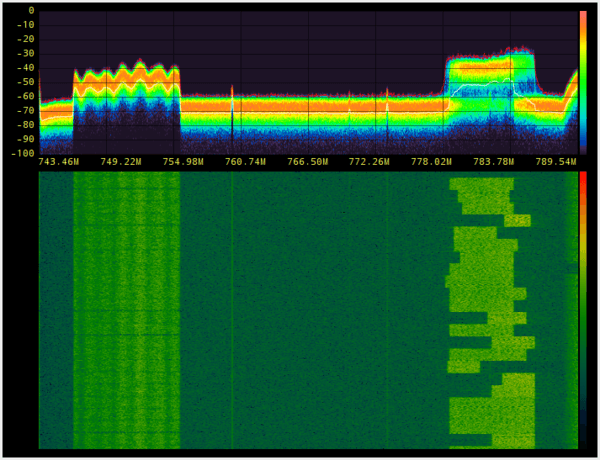
• “Understanding the LTE Physical Layer” with Sandor Szilvasi (@sszilvasi)

LTE is an incredible, yet complex, cellular networking standard. Sandor will break it down and explain how a LTE signal is constructed. He will also live demo the demodulation and decoding of local carriers.

LTE_cyberspectrum

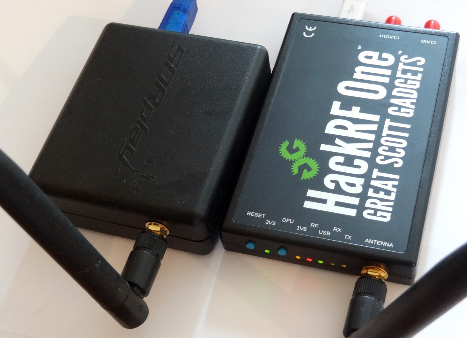
• “Interactive Install & Setup-fest” with the group

We would like to open up the forum to those who wish to get set up with SDR (hardware and/or software). Bring along your equipment, and as a group we can look at/debug the steps required to get you up and running. This could also include setting up an app, or fixing an Out-Of-Tree module, or even an environment issue on your laptop.

• “GNU Radio Tutorial Part 2” with Neel Pandeya

The tutorial series will continue! This time we will look at how to construct an FM radio receiver, and decode the RDS digital subcarrier. This will include:

• Explain concepts behind commercial FM and RDS
• Receiving mono FM using a from-scratch flowgraph
• Showing how to build ‘gr-rds’
• Demonstrate stereo FM+RDS reception using ‘gr-rds’
• Building GQRX
• Demonstrate FM reception using GQRX

SDR4Everyone: Review of the HackRF

Over on his ‘SDR4Everyone’ blog author Akos has recently uploaded a new post that reviews the HackRF One, and also compares it against the SDRplay RSP and RTL-SDR. In his review he discusses his first impressions of the HackRF, his concerns about it being labelled as a transceiver, and some of its various features. He also does a screenshot comparison of the HackRF, RSP and RTL-SDR on shortwave reception and image rejection performance. Akos also notes that there are not many applications in the high gigahertz range that cannot be done with cheaper or more specialized equipment. Finally he concludes that the HackRF is not very sensitive or good at RX in general, but still has enough features to make it a worthwhile purchase for some people.

If you are interested in the HackRF, we also have our own review that compares the HackRF, SDRplay RSP and Airspy.

The SDRplay and HackRF One.

Testing out the SDRplay with SDRuno and Characterizing RF HF Filters

Over on YouTube user Mile Kokotov has uploaded a video showing him using the SDRplay on the recently released official software SDRuno. In the video he first shows reception of some HF signals, then goes on to show how he can characterize some HF filters using a noise source.

Mile also wrote in to use to expand on his video. We quote:

“SDRuno” is new specialized software for SDRplay – RSP1 receiver. Besides many others excellent features, the new one is 10 MHz spectrum span on the window screen. The 10 MHz frequency span you can use it for characterize the HF Band-pass, Low-pass, High-pass or Notch filters. All you need is one noise source (noise generator) which you can find on eBay for about 20 USD.

With addition of directional coupler (for another 20$ USD), you can using SDRplay and SDRuno for HF antenna analyzer, measuring SWR like poore-man`s HF Vector Network Analyzer!

An RF filter is an electrical circuit designed to have specific characteristics with respect to the transmission or attenuation of various frequencies that may be applied to it.

There are three general types of RF filters:

1. A high-pass filter (HPF) similarly has a cut-off frequency, above which there is little or no loss in transmission, but below which there is considerable attenuation. Its behavior is the opposite of that of the low-pass filter.

2. A low-pass filter (LPF) is one that will permit all frequencies below a specified one called the cut-off frequency to be transmitted with little or no loss, but that will attenuate all frequencies above the cut-off frequency.

3. A band-pass filter (BPF) is one that will transmit a selected band of frequencies with substantially no loss, but that will attenuate all frequencies either higher or lower than the desired band.

The Filter connected in the front end of the receiver can be very much useful and it can improve the reception of the weak signals rejecting all others unwanted signals that can produces interference, intermodulation and as a results, the weak signals can not be copied !

With bandpass filter for particular frequency band, Receiving weak signals on that band is much easier, without problems from out of band strong sugnals.

73,
Mile Kokotov

SDRplay with SDRuno Using to characterize RF HF filters

Sniffing ANT-FS with an RTL-SDR and MMDS Downconverter in Pothos

ANT-FS is a wireless file transfer protocol that is designed specifically for transferring files wireless between two devices. It is designed for ultra low power devices and typically runs on devices operated by a coin sized battery. It is commonly used in applications like fitness tracker devices, which store data to later be downloaded to a PC.

Over on YouTube user sghctoma has uploaded a video showing a teaser of him receiving and decoding ANT-FS packets with blocks developed for the POTHOS graphical language. As ANT-FS is usually transmitted at 2.4 GHz, he had to use a MMDS downconverter which allowed his RTL-SDR to receive the packets. Sghctoma writes that the video is simply a teaser, and that a live demo with real deivce, and the full code + details will be released during his talk at DEFCON titled “Help, I’ve got ANTs!!!”.

ANT-FS sniffing with RTL-SDR, an MMDS downconverter and Pothosware

Testing L-Band Inmarsat Reception with Three LNA4ALL’s + Two Filters

Over the last few weeks Adam 9A4QV has been testing L-Band Inmarsat reception with his LNA4ALL low noise amplifiers. In a previous post he tested reception with two LNA4ALL and found that he got an improved SNR ratio over using just one LNA4ALL. In his latest video he tests Inmarsat reception with three LNA4ALL’s and two L-band filters. His results show that the SNR is improved over using two LNA4ALL’s, and can almost match the results obtained by a commercial L-band front end which he also demonstrated in a previous video.

3x LNA4ALL on L-band + 2 Filters

Instructions for Building a Portable Double Cross Antenna: Great for NOAA/Meteor Weather Satellites

Over on Reddit user merg_flerg has uploaded an imgur post that carefully details a step by step guide for building a double cross antenna. A double cross antenna is great for reception of satellites like NOAA and Meteor since it has a sky oriented radiation pattern with very few nulls. This means that it can receive satellite signals coming from the sky well. Alternative antennas for NOAA/Meteor include turnstiles and QFH antennas, although the double cross antenna seems to have the least nulls, meaning that the signal is less likely to fade in and out as the satellite moves across the sky.

merg_flerg’s design is also modified from the standard design slightly, allowing it to become easily disassembled and carried within a backpack. At the end of his tutorial he writes that he gets much better reception with his double cross antenna than he does with his QFH.

In the post he demonstrates the final constructed antenna decoding a NOAA APT weather satellite image with an RTL-SDR and the WXtoIMG software. See our tutorial for information on decoding NOAA weather satellite images.

The finished double cross antenna connected to a PC running an RTL-SDR and WXtoIMG.

50 Units of a $199 Nuand bladeRF x40 for Sale: 1-Day Only

Nuand is the company responsible for the bladeRF software defined radio. The bladeRF x40 is a SDR that usually costs $420. It uses a LimeMicro LMS6002D chip, which has a 12-bit ADC and a tuning range of 300MHz – 3.8GHz.

For one day only they have released a special price for the bladeRF x40 of $199 USD, for the first 50 customers only. At the time of this post the deal still seems to be active, and the coupon code of “MHZ” is still working. Of note is that the recently successfully crowdfunded LimeSDR uses the newer and better LimeMicro LMS7002M chip, so Nuand may be testing the waters for a lower price point on their bladeRF. However, one thing to note is that the bladeRF is proven hardware with active software applications, whereas the LimeSDR is not yet proven. 

Nuand also recently released an update which saw the source released for an ADS-B decoder that can be run on the bladeRF’s onboard FPGA, and also an update which allows the bladeRF to display up to 124 MHz of bandwidth at any one time. The large bandwidth display appears to work in a similar way to rtl_power or SpectrumSpy for the Airspy, by quickly switching between multiple chunks of frequency. The difference is that the bladeRF can do this by using onboard HDL accelerators which allow it retune extremely fast at several thousand times a second.

bladeRF displaying 96 MHz.

Building a Quad RTL-SDR Receiver for Radio Astronomy

Amateur radio astronomer Peter W East has recently uploaded a new document to his website. The document details how he built a quad RTL-SDR based receiver for his radio astronomy experiments in interferometry and wide-band pulsar detection (pdf – NOTE: Link Removed. Please see his website for a direct link to the pdf “Quad RTL Receiver for Pulsar Detection”. High traffic from this post and elsewhere has made the document go offline several times). Interferometry is a technique which uses multiple smaller radio dishes spaced some distance apart to essentially get the same resolution a much larger dish. Pulsars are rapidly rotating neutron stars which emit radio waves, and the strongest ones can be observed by amateur radio telescopes and a receiver like the RTL-SDR.

The Quad receiver has four RTL-SDR’s all driven by a single TCXO, mounted inside an aluminum case with fans for air cooling. He also uses a 74HC04 hex inverter to act as a buffer for the 0.5 PPM TCXO that he uses. This ensures that the TCXO signal is strong enough to drive all four RTL-SDRs.

The Quad RTL-SDR with air cooling.

Whilst all the clocks are all synced to a single master clock, synchronisation between the RTL-SDR’s is still difficult to achieve because of jitter introduced by the operating system. To solve this he introduces a noise source and a switch. By switching the noise source on and off, correlation of the signal data can be achieved in post processing.

Noise Source and Switch Calibration Unit.
How correlation with the pulsed noise source works.

In the document Peter shows in detail how the system is constructed, and how it all works, as well as showing some interferometry results. The system uses custom software that he developed and this is all explained in the document as well.