On this episode of Hak5 (a popular hacking and security themed YouTube channel) Darren and Shannon discuss OpenWebRX, a SDR web broadcasting and remote control tool that is compatible with the RTL-SDR. OpenWebRX is similar to the WebSDR software in that it allows people to connect to remote SDR’s on the internet and tune them to any station within their currently set bandwidth frequency range. Many already functioning online OpenWebRX receivers can be found in the database at sdr.hu.
In the first part of the video the Hak5 team explore the worldwide SDR’s on the sdr.hu website. Then in the second part they show a demonstration on how to install the OpenWebRX software in order to create a SDR broadcast with an RTL-SDR.
FREE SDR receivers all around the world with OpenWebRX - Hak5 1916
Radio transmissions between 0 - 30 MHz can travel all the way around the world. At these frequencies many interesting signals such as international shortwave radio, ham radio communications and several military transmissions exist.
The RTL-SDR's lowest tunable frequency is 24 MHz, and so it can only receive a small portion of the interesting transmissions that occur between 0 - 30 MHz. In order to listen to frequencies below 24 MHz an upconverter is required (either that or perform the direct sampling mod). An upconverter works simply by shifting these lower frequencies up to a higher frequency that the RTL-SDR can receive. For example, a 5 MHz signal might be upconverted to 105 MHz.
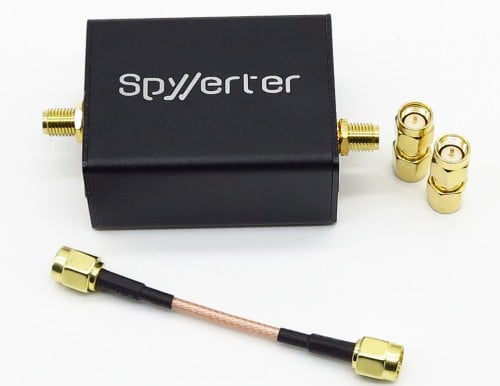
To date, most decent upconverters (such as the popular ham-it-up upconverter) have been based on the double balanced mixer architecture implemented by the ADE-1 mixer chip from Minicircuits. The SpyVerter on the other hand is based on a different type of architecture which is inspired by the H-mode mixer design that was used in the unreleased HF7070 communications receiver. The expected major advantage that this design has over a ADE-1 based design is better IIP3 performance. This essentially means that strong signals will not cause overloading issues in the SpyVerter, meaning less noise and spurious images.
Another advantage of the SpyVerter is its use of a 120 MHz low phase noise/low jitter clock, meaning less reciprocal mixing and thus greater SNR and a lower noise floor. A low phase noise clock is essential for getting good performance when receiving the very narrowband signals that are typically found between 0 - 30 MHz. The other upconverters do not specify their phase noise performance as far as we can tell.
The SpyVerter comes in a metal box, with three SMA adapters. A metal box is great because it helps keep strong interfering signals from entering the signal path, as well as stabilizing the internal temperature, keeping frequency drift to a minimum. Most upconverters only come with a metal box as a paid add on, but the SpyVerter comes in one by default.
Although the SpyVerter is designed to be used with the Airspy, it is fully compatible with the RTL-SDR as well. The SpyVerter can be powered via a USB cable, or via 5V bias tee (and this is compatible with the bias tee used on the RTL-SDR Blog units sold by us).
Adam (9a4QV) is well known in the RTL-SDR community for creating and selling the LNA4ALL low noise amplifier and several filter circuits as well. Now Adam has uploaded on his YouTube channel a new video that shows a prototype of his latest upcoming RTL-SDR compatible product called the MIX4ALL. The MIX4ALL is a downconverter that will improve the ability of the RTL-SDR to receive satellite signals in the L-band which are usually at around 1.5 GHz.
It is known that the most common R820T/2 RTL-SDR’s are not very sensitive at 1.5 GHz, and some can even stop receiving properly at this frequency when they get too hot. A downconverter will simply convert the 1.5 GHz signals into a lower frequency which can be received much better by the RTL-SDR.
In the first video Adam shows the MIX4ALL being used with an RTL-SDR to receive various Inmarsat signals with a patch antenna. In the second video he shows reception of AERO-I signals.
Adam writes that he expects to be able to sell the MIX4ALL near the end of January 2016.
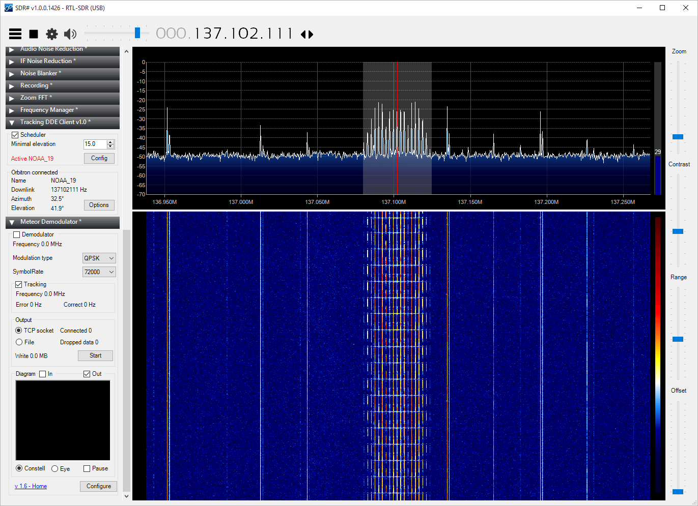
Recently a reader of our blog, Initrd, wrote in to let us know about a new tutorial he created that shows how to set up a dual NOAA APT and Meteor LRPT weather satellite monitoring station with an RTL-SDR dongle. These weather satellites transmit a live image of the portion of the earth that they are currently over, providing a valuable tool for weather analysis. APT transmissions are analogue and are transmitted by the American NOAA satellites, and the newer Meteor M2 satellite transmits a higher resolution image in the LRPT format. We also have posted separate tutorials that show how to set up NOAA APT and Meteor M2 LRPT decoding with an RTL-SDR, but Initrd’s tutorial appears to be a good all in one guide.
His tutorial takes you step by step through a process that involves setting up the satellite tracking software Orbitron, all the required SDR# plugins, the APT decoder WXtoIMG and the LRPT decoder. The tutorial also shows how to connect them all together and set them up so that APT and LRPT decoding can coexist.
Mario Filippi a regular contributor to our blog has recently written in with another article of his. This time he’s submitted an interesting article about ionosondes and how he listens to and watches them with an RTL-SDR dongle and upconverter. We present his article below.
Chirp Sounders and Those Ear-Jarring “Zwoops”
Written by Mario Filippi (N2HUN) – (All photos courtesy of author)
Have you ever experienced a loud disconcerting “zwoop” sound quickly passing through your headphones while listening to the HF or shortwave bands? Surely many of us have, and for years these odd sounding transmissions were a mystery, but the conundrum was unraveled one day when using my RTL-SDR (software defined radio) dongle for some HF (high frequency, 2MHz – 30MHz) listening. The HF band is populated by an array of non-voice (digital) signals from familiar modes such as CW, RTTY, and FAX to more contemporary modes such as ALE, PSK-31, and JT65, to name a few. Many different modes and sounds, both man-made and from Mother Nature, some familiar, some mysterious, inhabit the breadth of the HF band. These frequently heard “zwoops,” on different portions of the band definitely were in the “mysterious” category.
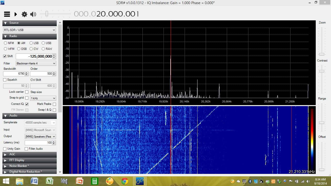
Over the past several years these high-pitched “zwoops” passing through my headset at lightning speed disturbed the calm of a normal evening spent listening to shortwave with my venerable boat anchor-like Yaesu FRG-7 receiver. However, further investigation using a RTL-SDR dongle (from www.rtl-sdr.com), Nooelec HamItUp upconverter, and SDR# software visualized these signals emanating from ionosondes. Their transmissions appear on the waterfall image as pulsed lines traveling up (and sometimes down) different segments of the HF band. Their purpose is helping to assess the ionosphere’s propagation status.
Author’s RTL-SDR dongle, Nooelec upconverter (in plexiglass case), and MJF antenna tuner.
In short, ionosondes, or ionospheric sounders, sometimes referred to as “chirp sounders” are transmitters that send out a radio signal across a specific frequency range, only to be heard by receivers at distant locations that analyze what the propagation characteristics are. Armed with this information, these analyses are an aid in two-way radio communications, such as determining the best frequencies to use at a given time by radio operators around the world. So what do these ionosonde transmissions appear like using the RTL-SDR and SDR# software? See some examples below.
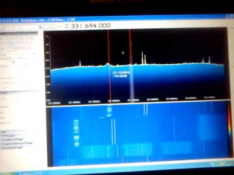
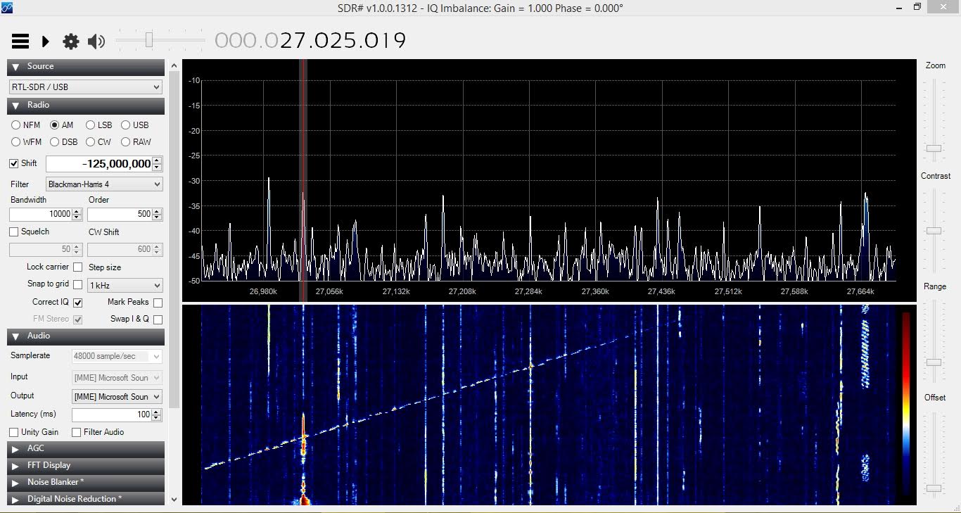
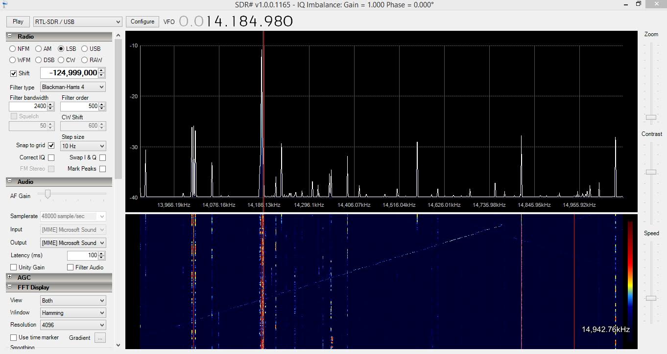
Chirp sounder appears as steeply-sloped line in center of SDR# waterfall. Strong signal at 20 MHz is time signal station WWV, Ft. Collins, CO.Pulse-like chirp sounder moving up the 15 meter (18.900MHz – 19.020MHz) shortwave band.CB (Citizen’s Band, 26.965MHz – 27.405MHz) band exhibiting chirp sounder activity.Weak chirp sounder in the 20 meter (14.000MHz – 14.350MHz) ham band.
Chirp sounder transmissions appear randomly as one navigates the HF bands and in the author’s experience are a hit and miss affair, but with the advent of software defined radios with real-time spectral displays of two megahertz or more in width, one can increase the possibility of hearing and seeing them more regularly. Note that ionosonde tracings on a waterfall can take many different shapes; I have shown only a few examples. The speed at which the ionosonde transmits up or down the band varies with the setup, but it’s an amusing signal to watch as it gracefully and speedily streaks across the band’s waterfall image with its’ meteor-like trail.
If you’d like to submit an article related to SDR, please remember to contact us at rtlsdrblog_AT_gmail.com.
QSpectrumAnalyzer is a Linux GUI for rtl_power which allows you to easily do wideband scans that are much wider than the RTL-SDR’s maximum bandwidth. RTL_power works by quickly switching between different frequencies and recording power values in each hop, then stitching them all together. A GUI for rtl_power can be used to display an FFT spectrum and waterfall for easy analysis.
Recently we posted about the release of rtl_power_fftw, which was a modified version of rtl_power. This modified version used a more efficient FFT library and reduces the acquisition time, which for rtl_power was capped at 1 second per scan. Essentially this means that rtl_power_fftw can do frequency scans much faster (though with less integration). In basic terms this means that you can now visualize large spectrum sweeps whilst having the waterfall look near real time.
Now QSpectrumAnalyzer has been updated to support rtl_power_fftw. To use rtl_power_fftw you’ll need to download and compile it yourself from https://github.com/AD-Vega/rtl-power-fftw. The compilation instructions are shown on the Github page, but you’ll also need to install the pkg-config, libtclap-dev and libfftw3-dev libraries first. Then once compiled in QSpectrumAnalyzer you can select the rtl_power_fftw binary in the settings.
Cyberspectrum is a monthly software defined radio meetup that is held in San Francisco. During this meetup presenters show and discuss their SDR related work. The 12th Cyberspectrum meetup is occurring right now and this time there will be presentations from amateur radio astronomer Marcus Leech from Canada and wireless security researcher Tobias Zillner from Austria.
There is a live stream on YouTube shown below, and after it finishes it will also be available for viewing:
Edit: Stream is over. Marcus Leech gave a nice talk that gave an overview or amateur radio astronomy and explained some of his set up where he uses RTL-SDR dongles as the receiver.
Cyberspectrum: Bay Area Software Defined Radio #12 (Dec 2015)
The overview of today’s presentations are as follows:
• Marcus Leech from SBRAC: “An integrated proof-of-concept ‘all-digital’ feed for 21cm radio astronomy”
We show ongoing work in designing and building a proof-of-concept ‘all digital’ feed for 21cm radio astronomy experiments. While many professional radio astronomy observatories are using “digitize at the feed” techniques, amateur experiments (and successes) in this are very close to non-existent.
Digitizing at the feed carries many advantages, including overall system gain stability, and the ability to carry signals over cheap ethernet-over-fiber links.
We’ll show an example feed arrangement that uses a differential radiometry approach, and does much of the initial processing right at the feed, including radiometry and spectral calculations, sending summary data to an ordinary PC host over ethernet.
Challenges and pitfalls will be discussed.
• Tobias Zillner from Cognosec: “ZigBee Smart Homes – A Hacker’s Open House”
ZigBee is one of the most widespread communication standards used in the Internet of Things and especially in the area of smart homes. If you have for example a smart light bulb at home, the chance is very high that you are actually using ZigBee by yourself. Popular lighting applications such as Philips Hue or Osram Lightify and also popular smart home systems such as SmartThings or Googles OnHub are based on ZigBee. New IoT devices have often very limited processing and energy resources. Therefore they are not capable of implementing well-known communication standards like Wifi. ZigBee is an open, public available alternative that enables wireless communication for such limited devices.
ZigBee provides also security services for key establishment, key transport, frame protection and device management that are based on established cryptographic algorithms. So a ZigBee home automation network with applied security is secure and the smart home communication is protected?
No, definitely not. Due to “requirements” on interoperability and compatibility as well as the application of ancient security concepts it is possible to compromise ZigBee networks and take over control of all included devices. For example it is easily possible for an external to get control over every smart light bulb that supports the ZigBee Light Link profile. Also the initial key transport is done in an unsecured way. It is even required by the standard to support this weak key transport. On top of that another vulnerability allows third parties to request secret key material without any authentication and therefore takeover the whole network as well as all connected ZigBee devices. Together with shortfalls and limitations in the security caused by the manufacturers itself the risk to this last tier communication standard can be considered as highly critical.
This talk will provide an overview about the actual applied security measures in ZigBee, highlight the included weaknesses and show also practical exploitations of actual product vulnerabilities. Therefore new features in the ZigBee security testing tool SecBee will be demonstrated and made public available.
Back in August of this year we showed how it was possible to use an RTL-SDR dongle, satellite antenna, LNA and decoding software to receive and decode STD-C EGC signals from Inmarsat satellites. We also showed how it was possible to modify a low cost GPS antenna to use as a satellite antenna.
Now a radio hobbyist called Jonti has released a Windows decoder for the Inmarsat AERO set of signals. AERO is a system that provides a satellite based version of VHF ACARS (Aircraft Communications Addressing and Reporting System). ACARS is typically used by ground control and pilots to send short messages and is also sometimes used for telemetry.
Jonti writes:
JAERO is a program that demodulates and decodes Classic Aero ACARS (Aircraft Communications Addressing and Reporting System) messages sent from satellites to Aeroplanes (SatCom ACARS) commonly used when Aeroplanes are beyond VHF range. Demodulation is performed using the soundcard. Such signals are typically around 1.5Ghz and can be received with a simple low gain antenna that can be home brewed in a few hours in conjunction with a cheap RTL-SDR dongle.
In the advent of MH370, Classic Aero has become a well-known name. A quick search on the net using “Classic Aero MH370” will produce thousands of results. The Classic Aero signals sent from satellites to the Aeroplanes are what JAERO demodulates and decodes.
Unlike the usual VHF ACARS, with SatCom ACARS you can not receive signals from the Aeroplane only the people on the ground talking to the people in the Aeroplane. This means you do not get the airplanes reporting their position. Instead you tend to get weather reports, flight plans, and that sort of stuff. Just like VHF ACARS they usually use cryptic shorthand notation. For example “METAR YSSY 040400Z 08012KT 9999 FEW040 SCT048 23/09 Q1024 FM0500 05012KT CAVOK=” is the weather report for Sydney Airport in Australia in a format called METAR. It tells you the time, when the report was issued, the wind direction and speed, visibility, clouds, temperature, due point and air pressure. Then it says from 5 AM UTC the wind direction and speed and that the weather will be nice. There are sites such as Flight Utilities that can decode such information and display it in a more understandable format.
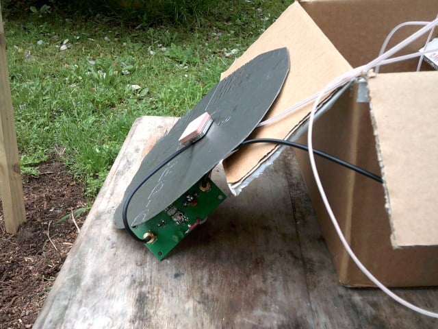
In his post Jonti also shows how he uses a modified GPS antenna to receive the AERO signals.
Jonti’s modified GPS antenna for receiving Inmarsat AERO
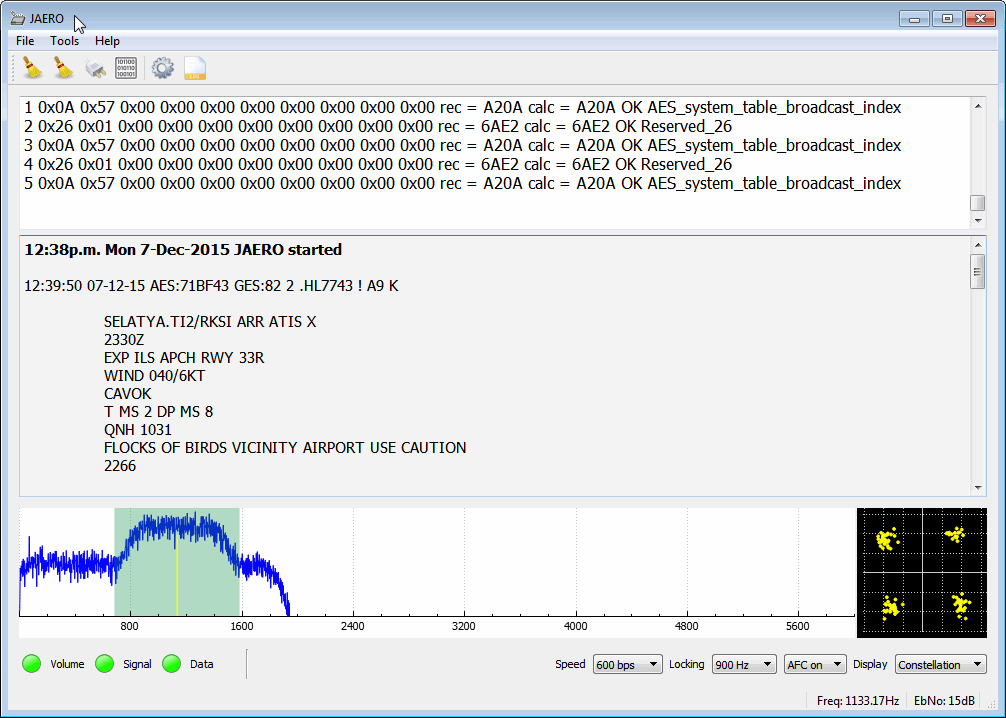
We gave JAERO a test and found that it decoded AERO signals easily, even with low signal strength. To use JAERO tune to an Inmarsat AERO signal in SDR# or a similar program using USB mode. JAERO will listen to the audio from the sound card or from a virtual audio pipe. We recommend setting the AFC (Automatic Frequency Control) setting on on if you find that your RTL-SDR drifts too much.
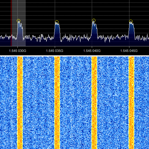
AERO signals can be found at around 1545 MHz. They only use about 800 Hz in bandwidth. See UHF satcoms page for a list of AERO frequencies.
The JAERO decoder.Some AERO signals.
Remember that some R820T/2 RTL-SDR dongles can have problems when receiving this high, especially when they heat up. If you find that your dongle gets deaf at these L-band frequencies try cooling the R820T/2 chip with a heatsink or fan. The Airspy or SDRplay RSP software defined radios are better choices for decoding signals this high, but the RTL-SDR will work fine if your signal strength is decent and the R820T/2 chip is kept cool.
If you are interested in VHF ACARS as well, then we have a tutorial about decoding that here.