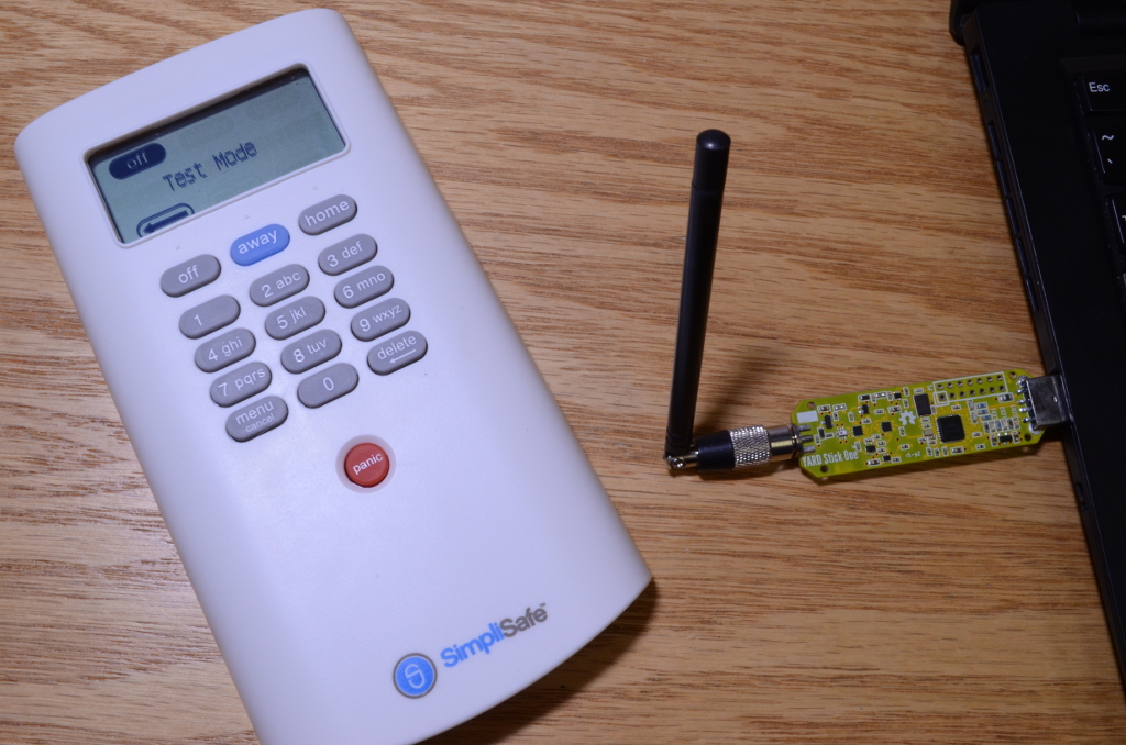
SimpliSafe is a home security system that relies on wireless radio communications between its various sensors and control panels. They claim that their system is installed in over 300,000 homes in North America. Unfortunately for SimpliSafe, earlier this week Dr. Andrew Zonenberg of IOActive Labs published an article showing how easy it is for an attacker to remotely disable their system. By using a logic analyser he was able to fairly easily reverse engineer enough of the protocol to discover which packets were the “PIN entered” packets. He then created a small electronic device out of a microcontroller that would passively listen for the PIN entered packet, save the packet into RAM, and then replay it on demand, disarming the alarm.
A few days later Micheal Ossmann (wireless security researcher and creator of the HackRF SDR and YardStick One) decided to have a go at this himself, using a YARD Stick One and a HackRF SDR. First he used the HackRF to record some packets to analyze the transmission. From the analysis he determined that the protocol was an Amplitude Shift Keying (ASK) encoded signal. With this and some other information he got from the recorded signal, he could then use his Yardstick One to instantly decode the raw symbols transmitted by the keypad and perform a replay attack if he wanted to.
Next, instead of doing a capture and replay attack like Andrew did, Micheal decided to take it further and actually decode the packets. This took him a few hours but it turned out to not be too difficult. Now he is able to recover the actual PIN number entered by a home owner from a distance without having to do any transmitting. With the right antenna someone could be gathering 100’s of PINs over a distance of many miles. Also, an expensive radio is not required, Micheal notes that the gathering of PIN numbers could just as easily be done on a cheap $10-$20 RTL-SDR dongle.
Micheal notes that the SimpliSafe alarm seems to lack even the most basic cryptographic protection, and that this is a problem that is seen all too often in wireless alarm systems. Rightly so, Micheal and Andrew are not publishing their code, although it seems that anyone with some basic knowledge could repeat their results.
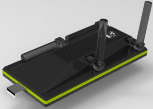
The people behind this SDR are currently marketing SoDeRa as “the Arduino of the Telecom and Radio Engineer”. It appears to be designed mainly to implement IoT and other radio communications protocols, but it also sounds like it could find excellent use in the hobby and amateur market as well as have benefits for the average person. Interestingly, the developers also plan to implement an app store which would allow you to essentially download a radio and instantly configure the SoDeRa SDR for any desired protocol or application. They write:
This is the first time that a revolutionary device for which we are organising a joint crowd-funding campaign with Lime Microsystems is made public. The #SoDeRa is the cheapest software defined radio you can buy. The #SoDeRa will have an app store and will be able to provide any type of (bi-directional) radio communication going from LTE, Lora, WiFi, GPS, Bluetooth, radar, radio-controlled toys/robots/drone, digital radio, digital TV to even MRI scanners, satellite and air traffic communications by just installing an app. The #SoDeRa is the Arduino of the Telecom and Radio Engineer.
The SoDeRa is powerful enough to be a full MiMo LTE base station with long range coverage, provided you add the right antenna. You can via apps put other wireless communication protocols like LoRaWAN, Bluetooth, Zigbee, Z-Wave, GPS, Galileo, Airspace protocols, radar, MRI scanning RF, TV/Radio, any toy/robot/drone control, White Space, etc. But most importantly because of its price and ease of adding more protocols, the SoDeRa will enable anybody to define competing wireless communication protocols and put them into Github. Developers don’t like closed standards like LTE or complex standards like Bluetooth & Zigbee. The future will allow developers to compete against corporations and standardization bodies if they think current standards can be improved upon. The Internet has shown that this dynamic brought us easier standards through adoption like JSON and Yaml vs XML and EDI. Wireless, RF and telecom engineers never had an Arduino like the electronics engineers. The SoDeRa will plug this hole.
Development on SoDeRa is working towards a trend in radio systems where all radio devices are software defined, allowing for futuristic features like advanced spectrum control and the ability to change protocols on the fly. They write:
Including #SoDeRa in any type of smart device will greatly reduce the cost of deploying a mobile base station network because by open sourcing the hardware design it will become commodity. By including software defined radio in lots of devices, often with a completely different purpose, will allow these devices to become a smart cell via installing an extra app. In the future, support for software defined radio will likely be embedded directly in Intel and ARM chips. The foundational steps are already happening. This will likely reshape the telecom industry. Not only from a cost perspective but also from a perspective of who runs the network. Telecom operators that don’t deliver value will see their monopoly positions being put in danger. As soon as spectrum can be licensed on a per hour basis, just like any other resource in the cloud, any type of ad-hoc network can be setup. The question is not if but when. Open sourcing and crowdfunding will make that “when” be sooner than later. Smart operators that align with the innovators will win because they will get the app revenue, enormous cost reductions, sell surplus spectrum by the hour and lots of innovation. Other operators that don’t move or try to stop it will be disrupted. What do you want to be?
At first glance SoDeRa sounds like it will be an expensive device, but on their official website they are currently running a survey asking people what they would be willing to pay, and the lowest price given is $50 – $99. This makes it seem likely that in the future with enough volume SoDeRa could be sold at very low cost and become very popular.
I am willing to pay for 1 unit
$50 – $99 (lead time 9 months)
$100 – $199 (lead time 6 months)
$200 – $299 (lead time 3 months)
$300 – $399 (lead time 2 months)
$400 – $500 (lead time 1 month)
It sounds like the team behind SoDeRa are gearing up for a crowd funding campaign so we will be keeping an eye on this SDR.
Thanks to RTL-SDR.com reader Serdar (TA3AS) for submitting news about SoDeRa to us.
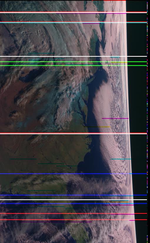
The Meteor M N-2 is a polar orbiting Russian weather satellite that was launched in July 2014. It transmits with the LRPT protocol which allows us to receive weather satellite images that are of a much higher resolution than the NOAA APT satellites. For a while since the launch RTL-SDR users had a good time receiving beautiful images from Meteor M-N2, but unfortunately since late last year the N2 LRPT transmitter has been turned off, due to technical problems with the IR sensors as cited by Russian meteorologists.
Fortunately for Meteor N2 enthusiasts the old Meteor M N1 satellite which was thought to be dead sprung back into life around November 2015. Recently Matthew A., a reader of our blog wrote in to let us know that while N2 is still not transmitting, N1 is still transmitting, albeit with somewhat distorted images. Matthew also mentions this link: http://homepage.ntlworld.com/phqfh1/status.htm, which contains up to date info on the status of all weather satellites. He also writes:
While transmissions are readily detectable and decodable at night, it seems that M N-1’s infrared sensors are not functioning. Yielding only black, with the typical noise bars of Red, Green, or Blue
As has been previously mentioned, Meteor MN-1’s stabilization system has obviously failed, and the horizon is clearly visible. Perhaps not of scientific value, but certainly beautiful.
We also note that there are several comments over on the Meteor-M N2 news and support website regarding receiving images from N1 and N2. It seems that sometimes N1 also has some problems with transmission, but they are usually quickly fixed.
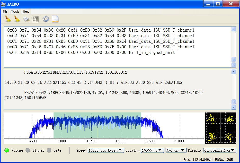
Jonti, the programmer of JAERO has recently updated his software to version 1.04 which can now be used to decode C-Band AERO signals. Previously only L-Band (1.5 GHz) AERO signals could be decoded with JAERO. C-Band signals are much harder to receive as they are at 3.6 GHz, so require an LNB, and they are also much weaker so require a large dish (at least about 1.8 meters or larger in diameter). However, the interest in them is that C-Band AERO signals arguably contain more interesting information that the L-Band AERO data. They contain actual aircraft position data which would allow you to plot the locations of all planes using that satellite. About the information that can be received Jonti writes:
The L band Aero signals (around 1.54GHz) that everyone has been decoding lately using JAERO are the very strong signals being sent from the satellites to the airplanes, this is the information that is being sent from the GESs (ground earth stations i.e. the people on the ground) to the AESs (air earth stations i.e. the people in the airplanes). A modified 2cm GPS antenna, an LNA (Low Noise Amplifiers) or two, and an SDR receiver is enough to receive such signals.
Receiving the information going the other way around from the people in the airplanes to the people on the ground is a lot more challenging. This AES to GES information first gets transmitted from the airplanes around 1.6 GHz to the satellites which is then relayed back down to the GES people on the C-band around 3.6 GHz. that means to receive information from the airplanes the only practical option is to receive the 3.6 GHz frequencies. This is above any SDR receiver I know of. To make things worse, I believe the signals are 11dB weaker than the L band ones that everyone has been receiving. Complicating matters further the signals are transmitted in bursts and each burst is dependent on the airplane’s L band transmitter. So a weaker L band transmitter on a plane produces a weaker C-band burst transmission, likewise any frequency offset of an L band transmitter on the plane produces a frequency offset on the C-band.
So what’s so attractive about C-band Aero signals?
Two reasons spring to mind. The first is the challenge of receiving and demodulating it and the second is this information contains plane location information like ADS-B (Automatic dependent surveillance – broadcast) so you can produce pretty pictures of where all the planes are in the world.
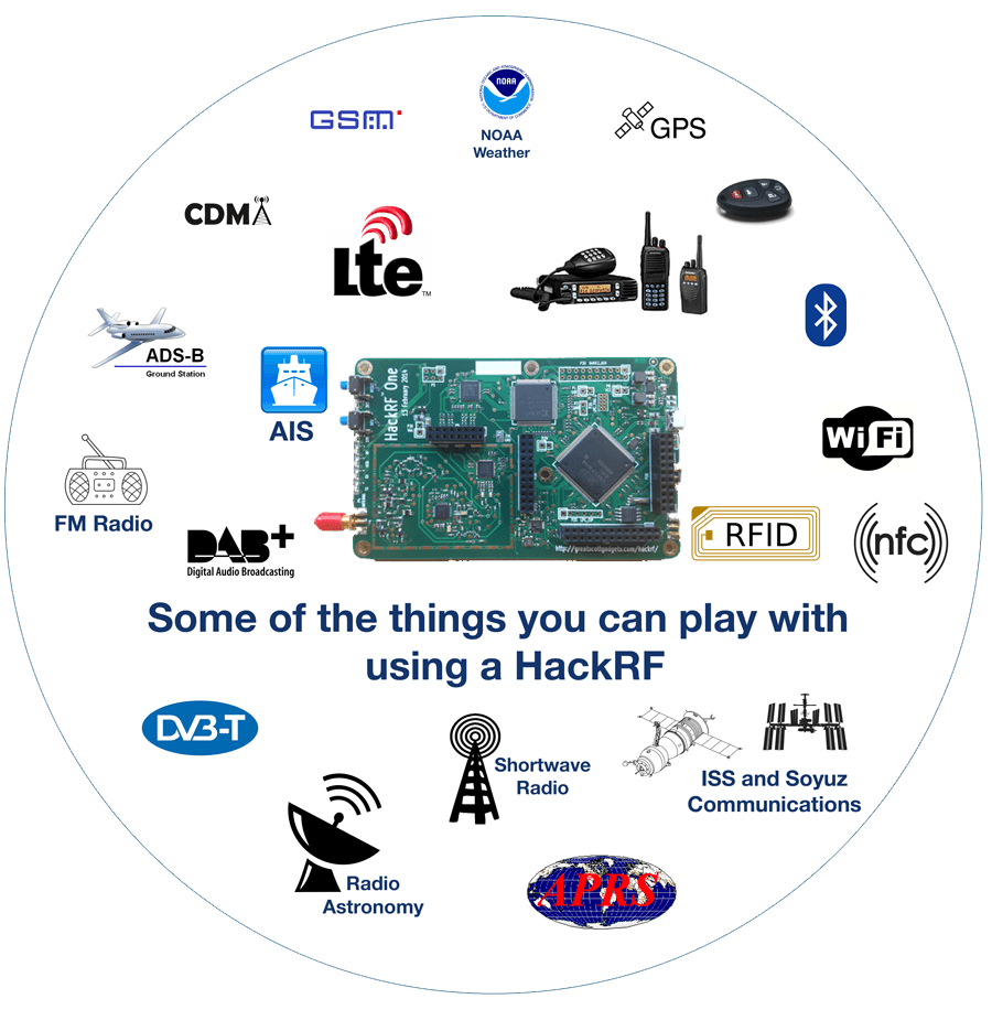
Back in December 2014 the HackRF Blue came out via a crowd funded Indiegogo campaign as a HackRF board that was $100 cheaper than the official version ($199 vs $299 USD). The HackRF is a 8-bit receive and transmit capable SDR with operating range of between 0.1 – 6000 MHz and a bandwidth of up to 20 MHz. As its hardware specifications are released as open source, it is very easy for clones of the official version to be produced. While the HackRF Blue Indiegogo campaign was successful, the product is now out of stock as they seemed to stop production after the campaign.
We are a PCB and SMT assembly factory founded in the year 2001, located in Shenzhen, China. We are a professional EMS/OEM company; provide one-stop contract electronic manufacturing service for PCB&PCBA. Now we want to make small market devices and sell directly to customers.
Some of the part on HackRF is End Of Life and very difficult to find now. We have enough of these part for ~300 HackRF only. You can find some HackRF on Alibaba right now, but they used cheap parts and the manufacture does not test them (they do not install any firmware).
We are trying to find some more of the EOL part first and will make the Kickstarter campaign soon. If we can’t find any more of these part, we will only make ~300pcs. Please register first, when we activate the campaign we will tell you by email. The first 10 people who buy from the Kickstarter will have a heavy discount, only pay $75!
Over on his blog, Twitch has uploaded a post showing how he mounted two RTL-SDR dongles into a single metal case in order to reduce noise. Twitch used a $2 aluminium metal case that he obtained from a local surplus shop and cut it down to size and added holes for switches and BNC plugs. He then mounted two RTL-SDR dongles in the case and used two MCX -> BNC pigtails to get a case mounted coax connector.
He also removed the USB plugs on the RTL-SDR’s and wired them into a USB B plug mounted to the case, making sure to wind the USB power cables through several turns of ferrite core in order to reduce USB noise. Finally he also added a power switch to the USB connections, to be able to easily power off the units when not in use.
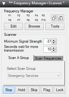
Recently the commonly used Frequency Manager Suite Plugin for SDR# has been updated. The plugin suite works well with the RTL-SDR and includes features such as a frequency scanner and manager, a scanner metrics recorder, a scheduler, an activity logger and a frequency entry plugin. The changelog is shown below:
Frequency Manager + Scanner
New feature: you may now optionally display the descriptions of frequencies in your database on the spectrum window. You control the colors and transparency of the descriptions and their marker lines.
New feature: the Browse window now allows you to type a frequency directly into the grid, and the grid will dynamically filter your database to matching frequencies. You may type a partial frequency and all frequencies that start with the same digits will be displayed. The more digits you type, the more specific the filtering.
New feature: A checkbox in Preferences lets you control whether the Last Update field is changed when performing bulk edits. When unchecked this permits you to retain the original date and time the frequency was recorded in the database.
New feature: You may now change the font size in the Scanner Decisions window and plugin. The new size will be remembered and used the next time you start SDR#.
New article: User David Bunyan has provided a how-to article in the Appendix on how to use the scanner effectively for WFM DXing. See also the WFM DXing Databases download in the Download Here section to get pre-built databases for different regions around the world, also graciously provided by David Bunyan.
Scanner Metrics
Bug fix: fixed error in the queue manager that prevented recording activity when the date-time format on the computer was not United States.
Bug fix: fixed error that prevented SM from putting its database in the same folder as FM, if the FM database location was changed after SM was loaded.
Data Tools
New feature: default values for imports. Will automatically assign values when they are missing from the source import data.
Bug fix: Fixed culture-specific issue with Frequency values when an Eibi database is downloaded.
Bug fix: Fixed bug that caused Data Tools to change the current database in Frequency Manager + Scanner.
Bug fix: Importing an SDR# Frequency Manager data file now results in a prompt to add or replace existing data in the target FMSuite database.
The Pluginator
New feature: The Pluginator now knows many of the most popular plugins. So now you may simply select one from a list and it will be installed to Plugins.xml, as opposed to requiring you to type the configuration data for the chosen plugin.
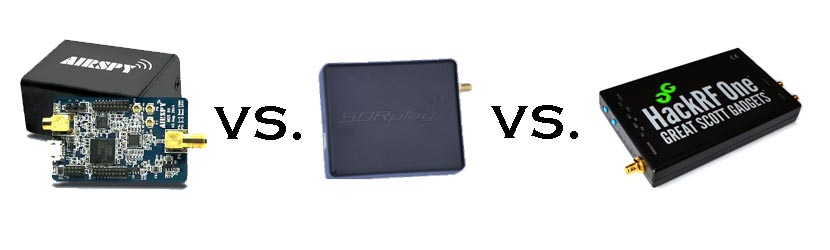
IMPORTANT NOTE: Please note that this review is now out of date as the SDRplay RSP line has received significant improvements to their hardware and Airspy have brought out a new SDR that is much better at HF.
Overall it is now difficult to pick a winner between Airspy and SDRplay products. However, our preference is the Airspy HF+ Discovery for HF signals, and the SDRplay RSP1A for generic wideband wide frequency range receiving.
When people consider upgrading from the RTL-SDR, there are three mid priced software defined radios that come to most peoples minds: The Airspy (store), the SDRplay RSP (store) and the HackRF (store). These three are all in the price range of $150 to $300 USD. In this post we will review the Airspy, review the SDRplay RSP and review the HackRF and compare them against each other on various tests.
Note that this is a very long review. If you don't want to read all of this very long post then just scroll down to the conclusions at the end.
What makes a good SDR?
In this review we will only consider RX performance. So first we will review some terminology, features and specifications that are required for a good RX SDR.
SNR - When receiving a signal the main metric we want to measure is the "Signal to Noise" (SNR) ratio. This is the peak signal strength minus the noise floor strength.
Bandwidth - A larger bandwidth means more signals on the screen at once, and more software decimation (better SNR). The downside is that greater CPU power is needed for higher bandwidths.
Alias Free Bandwidth - The bandwidth on SDR displays tends to roll off at the edges, and also display aliased or images of other signals. The alias free bandwidth is the actual usable bandwidth and is usually smaller than the advertised bandwidth.
Sensitivity - More sensitive radios will be able to hear weaker stations easier, and produce high SNR values.
ADC - Analogue to digital converter. The main component in an SDR. It samples an analogue signal and turns it into digital bits. The higher the bit size of the ADC the more accurate it can be when sampling.
Overloading - Overloading occurs when a signal is too strong and saturates the ADC, leaving no space for weak signals to be measured. When overloading occurs you'll see effects like severely reduced sensitivity and signal images.
Dynamic Range - This is directly related to ADC bit size, but is also affected by DSP software processing. Dynamic range is the ability of an SDR to receive weak signals when strong signals are nearby. The need for high dynamic range can be alleviated by using RF filtering. Overloading occurs when a strong signal starts to saturate the ADC because the dynamic range was not high enough.
Images/Aliasing - Bad SDRs are more likely to overload and show images of strong signals at frequencies that they should not be at. This can be fixed with filtering or by using a higher dynamic range/higher bit receiver.
Noise/Interference - Good SDRs should not receive anything without an antenna attached. If they receive signals without an antenna, then interfering signals may be entering directly through the circuit board, making it impossible to filter them out. Good SDRs will also cope well with things like USB interference.
RF Filtering/Preselection - A high performance SDR will have multiple preselector filters that switch in depending on the frequency you are listening to.
Center DC Spike - A good SDR should have the I/Q parts balanced so that there is no DC spike in the center.
Phase Noise - Phase noise performance is determined by the quality of the crystal oscillators used. Lower phase noise oscillators means better SNR for narrowband signals and less reciprocal mixing. Reciprocal mixing is when high phase noise causes a weak signal to be lost in the phase noise of a nearby strong signal.
Frequency Stability - We should expect the receiver to stay on frequency and not drift when the temperature changes. To achieve this a TCXO or similar stable oscillator should be used.
RF Design - The overall design of the system. For example, how many lossy components such as switches are used in the RF path. As the design complexity increases usually more components are added to the RF path which can reduce RX performance.
Software - The hardware is only half of an SDR. The software the unit is compatible with can make or break an SDRs usefulness.
Next we will introduce each device and its advertised specifications and features:
Device Introduction and Advertised Specifications & Features
As of April 2016, the Airspy Mini is now also for sale at $99 USD.
$149 USD + shipping ($20-$30 world, free shipping in the USA)
£99 + VAT + ~£10 shipping for EU.
$299 USD + shipping
Freq. Range (MHz)
24 - 1800
0 - 1800 (with Spyverter addon)
0.1 - 2000
0.1 - 6000
ADC Bits
12 (10.4 ENOB)
12 (10.4 ENOB)
8
Bandwidth (MHz)
10 (9 MHz usable)
6 MHz (5 MHz usable) (AS Mini)
8 (7 MHz usable) (10 MHz in SDRuno/~9 MHz usable)
20
TX
No
No
Yes (half duplex)
Dynamic Range (Claimed)(dB)
80
67
~48
Clock Precision (PPM)
0.5 PPM low phase noise TCXO
10 PPM XO
30 PPM XO
Frontend Filters
Front end tracking IF filter on the R820T2 chip.
8 switched preselection filters + switchable IF filter on MSI001 chip
Two very wide preselection filters - 2.3 GHz LPF, 2.7 GHz HPF
ADC, Frontend Chips
LPC4370 ARM, R820T2
MSi2500, MSi001
MAX5864, RFFC5071
Additional Features
4.5v bias tee, external clock input, expansion headers.
LNA on the front end
5v bias tee, LNA on front end, external clock input, expansion headers.
Notes
The Airspy is designed by Benjamin Vernoux & Youssef Touil who is also the author of the popular SDR# software.
Of note is that there has been a misconception going around that the Airspy is an RTL-SDR/RTL2832U device. This is not true; there are no RTL2832U chips in the Airspy. The confusion may come from the fact that they both use the R820T2 tuner. The RTL2832U chip is the main bottleneck in RTL-SDR devices, not the R820T2. When coupled with a better ADC, the R820T2 works well and can be used to its full potential.
The Airspy team write that they sell units mostly to universities, governments and professional RF users. However, they also have a sizable number of amateur users.
Update: As of April 2016 the Airspy Mini is now for sale for $99 USD. The main difference is a 6 MHz bandwidth and fewer expansion headers, but all other specs appear to be the same.
The SDR Play Radio Spectrum Processor (RSP) is designed by UK based engineers who appear to be affiliated with Mirics, a UK based producer of SDR RF microchips.
The chips used in the SDRplay RSP are dedicated SDR chips which were designed for a wide variety of applications such as DVB-T tuners. The RSP uses these chips and improves on their front end capabilities by adding an LNA and filters in order to create a device capable of general SDR use.
Initially when writing this review we had deep problems with the imaging of strong signals on the RSP. However, a recent Dec 22 update to the drivers has fixed this imaging problem tremendously.
The HackRF is designed by Micheal Ossmann a computer security researcher who was given a development grant from DARPA. His company is called "Great Scott Gadgets".
The HackRF's most unique feature when compared to the other two SDR's is that it is capable of both receiving and transmitting.
There is also a clone called the HackRF Blue out on the market which is about $100 cheaper, but they don't seem to have stock or be producing these any more.
From the specs it is clear from the ADC sizes that both the Airspy and SDRplay RSP are in a different class of RX performance when compared to the HackRF. However, people always compare the Airspy and SDRplay with the HackRF due to their similar price range, so we will continue to compare the three here in our review, but with more of a focus on comparing the Airspy and SDRplay RSP.
In order to use the Airspy on HF (0 - 30 MHz) frequencies a $50 add on called the Spyverter is required. This is an upconverter that is designed for use with the Airspy's high dynamic range and bias tee power port. However, one hassle is that the Spyverter must be connected/disconnected each time you want to switch between HF and VHF/UHF reception as it does not have VHF/UHF passthrough. The RSP and HackRF on the other hand can receive HF to UHF without the need of an upconverter or the need to change ports. A single port for HF to UHF can be very useful if you have a remote antenna switcher.
Post continues. Note that this is a long post with many images.